BMW MOTORRAD R 1150 GS 2002 Rider's Manual (in English)
Manufacturer: BMW MOTORRAD, Model Year: 2002, Model line: R 1150 GS, Model: BMW MOTORRAD R 1150 GS 2002Pages: 104, PDF Size: 7.54 MB
Page 11 of 104
111
9
General information and controls
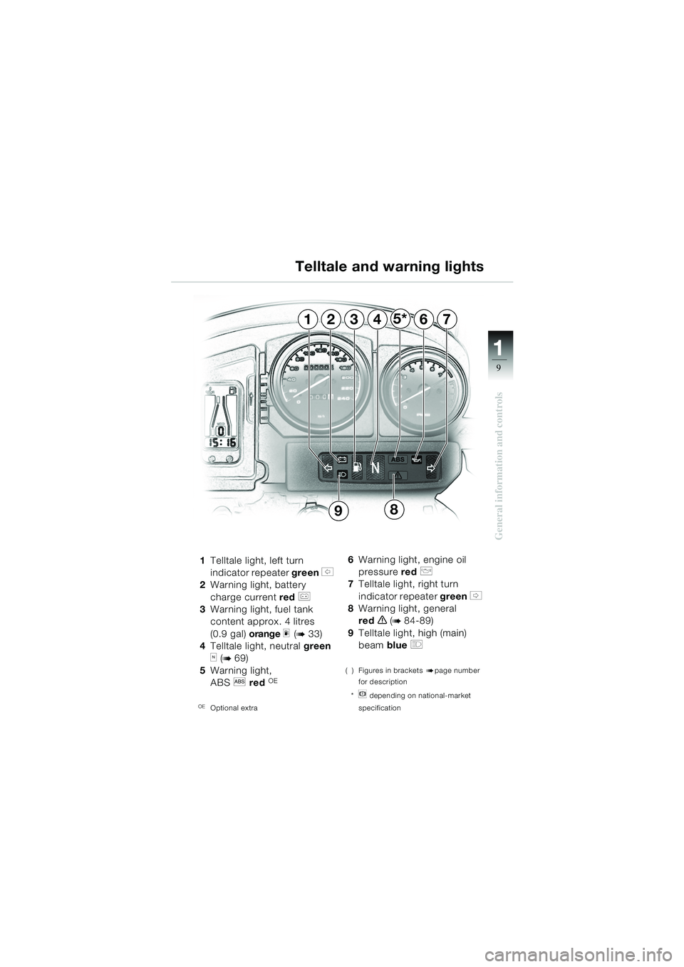
1Telltale light, left turn
indicator repeater green
s
2 Warning light, battery
charge current red
r
3 Warning light, fuel tank
content approx. 4 litres
(0.9 gal) orange
m (b33)
4 Telltale light, neutral green
k (b69)
5 Warning light,
ABS
l red OE
OEOptional extra
6Warning light, engine oil
pressure red
p
7Telltale light, right turn
indicator repeater green
t
8 Warning light, general
red
e (b 84-89)
9 Telltale light, high (main)
beam blue
q
( ) Figures in brackets bpage number
for description
*
n depending on national-market
specification
Telltale and warning lights
124637
9
5*
8
10geBKg6.book Seite 9 Dienstag, 19. November 2002 1:11 13
Page 12 of 104
11
10
General information and controls
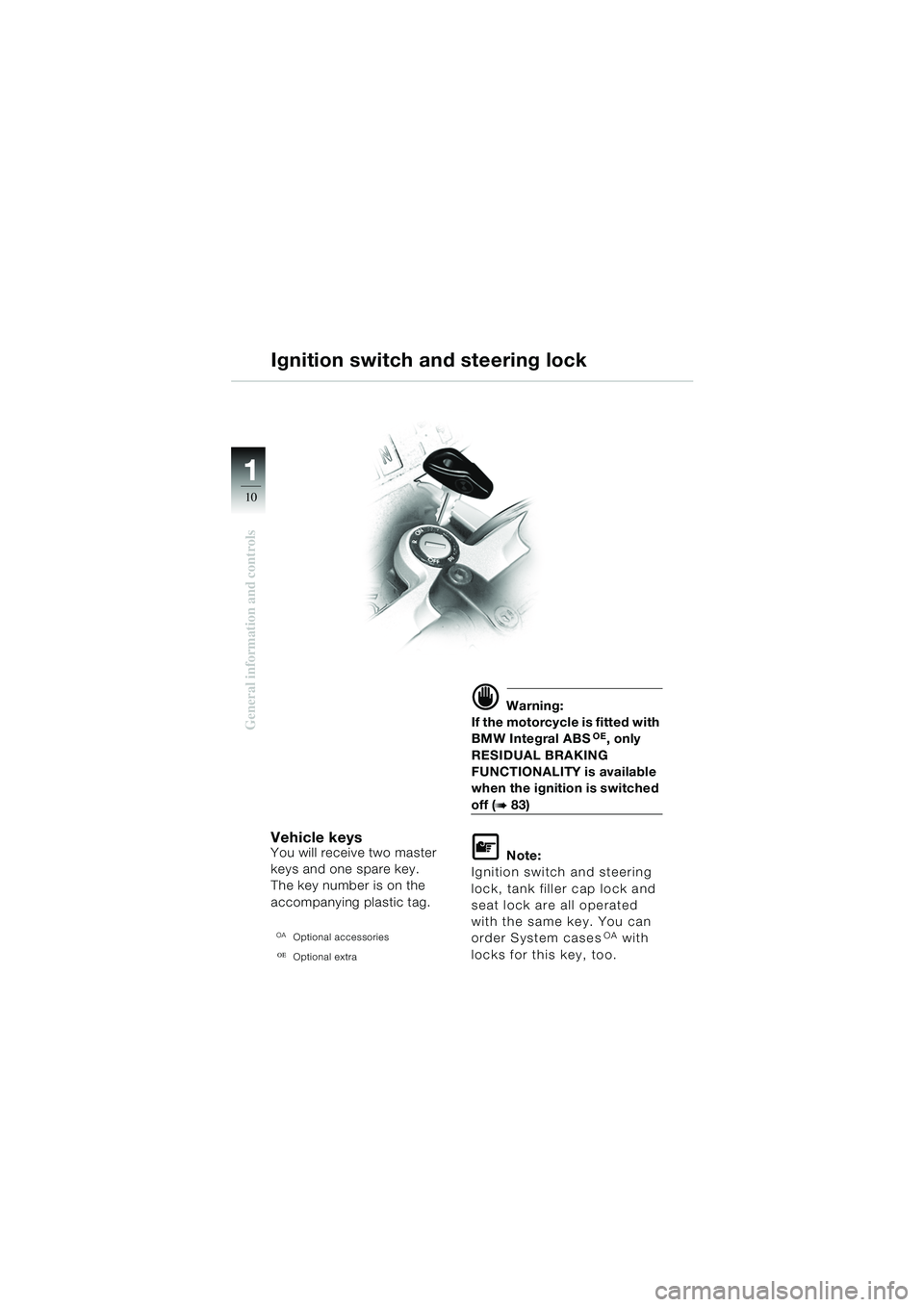
Vehicle keysYou will receive two master
keys and one spare key.
The key number is on the
accompanying plastic tag.
OAOptional accessories
OEOptional extra
d Warning:
If the motorcycle is fitted with
BMW Integral ABS
OE, only
RESIDUAL BRAKING
FUNCTIONALITY is available
when the ignition is switched
off (b83)
L Note:
Ignition switch and steering
lock, tank filler cap lock and
seat lock are all operated
with the same key. You can
order System cases
OA with
locks for this key, too.
Ignition switch and steering lock
10geBKg6.book Seite 10 Dienstag, 19. November 2002 1:11 13
Page 13 of 104
111
11
General information and controls
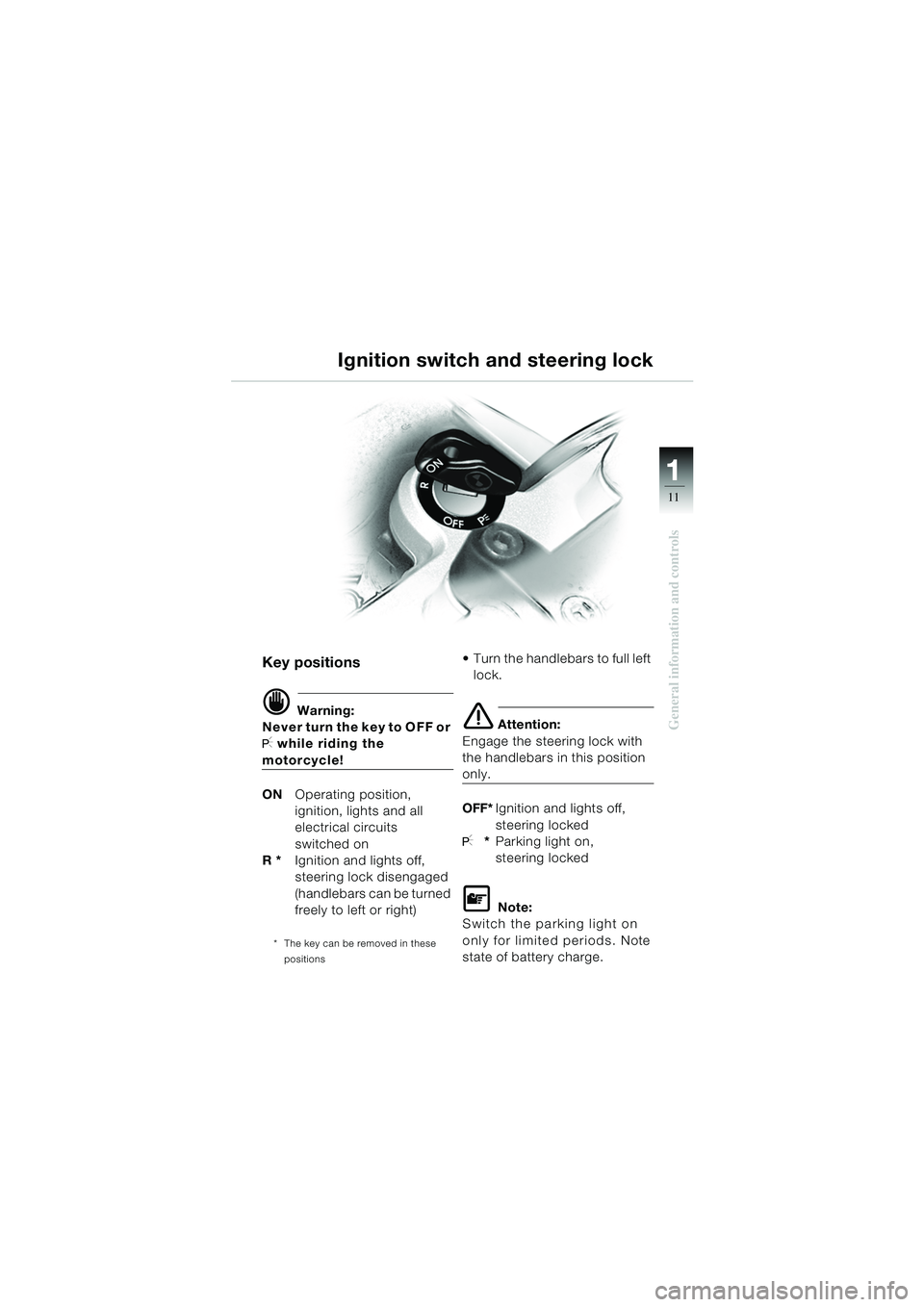
Key positions
d Warning:
Never turn the key to OFF or
I while riding the
motorcycle!
ON Operating position,
ignition, lights and all
electrical circuits
switched on
R * Ignition and lights off,
steering lock disengaged
(handlebars can be turned
freely to left or right)
* The key can be removed in these
positions
Turn the handlebars to full left lock.
e Attention:
Engage the steering lock with
the handlebars in this position
only.
OFF* Ignition and lights off,
steering locked
I**Parking light on,
steering locked
L Note:
Switch the parking light on
only for limited periods. Note
state of battery charge.
Ignition switch and steering lock
10geBKg6.book Seite 11 Dienstag, 19. November 2002 1:11 13
Page 14 of 104
11
12
General information and controls
Hazard warning lights
L Note:
You cannot activate the hazard
warning flashers if the ignition is
switched off.
Do not use the hazard warning
flashers for longer than abso-
lutely necessary.
Note state of battery charge.
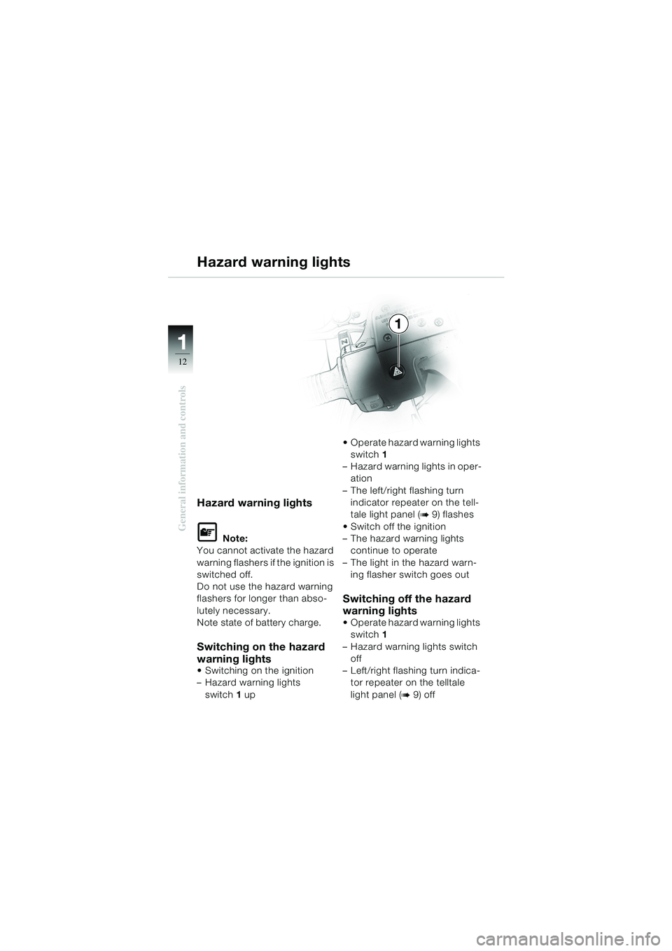
Switching on the hazard
warning lights
Switching on the ignition
– Hazard warning lights switch 1 up Operate hazard warning lights
switch 1
– Hazard warning lights in oper- ation
– The left/right flashing turn indicator repeater on the tell-
tale light panel (
b9) flashes
Switch off the ignition
– The hazard warning lights continue to operate
– The light in the hazard warn- ing flasher switch goes out
Switching off the hazard
warning lights
Operate hazard warning lights switch 1
– Hazard warning lights switch off
– Left/right flashing turn indica- tor repeater on the telltale
light panel (
b9) off
Hazard warning lights
1
10geBKg6.book Seite 12 Dienstag, 19. November 2002 1:11 13
Page 15 of 104
111
13
General information and controls
1
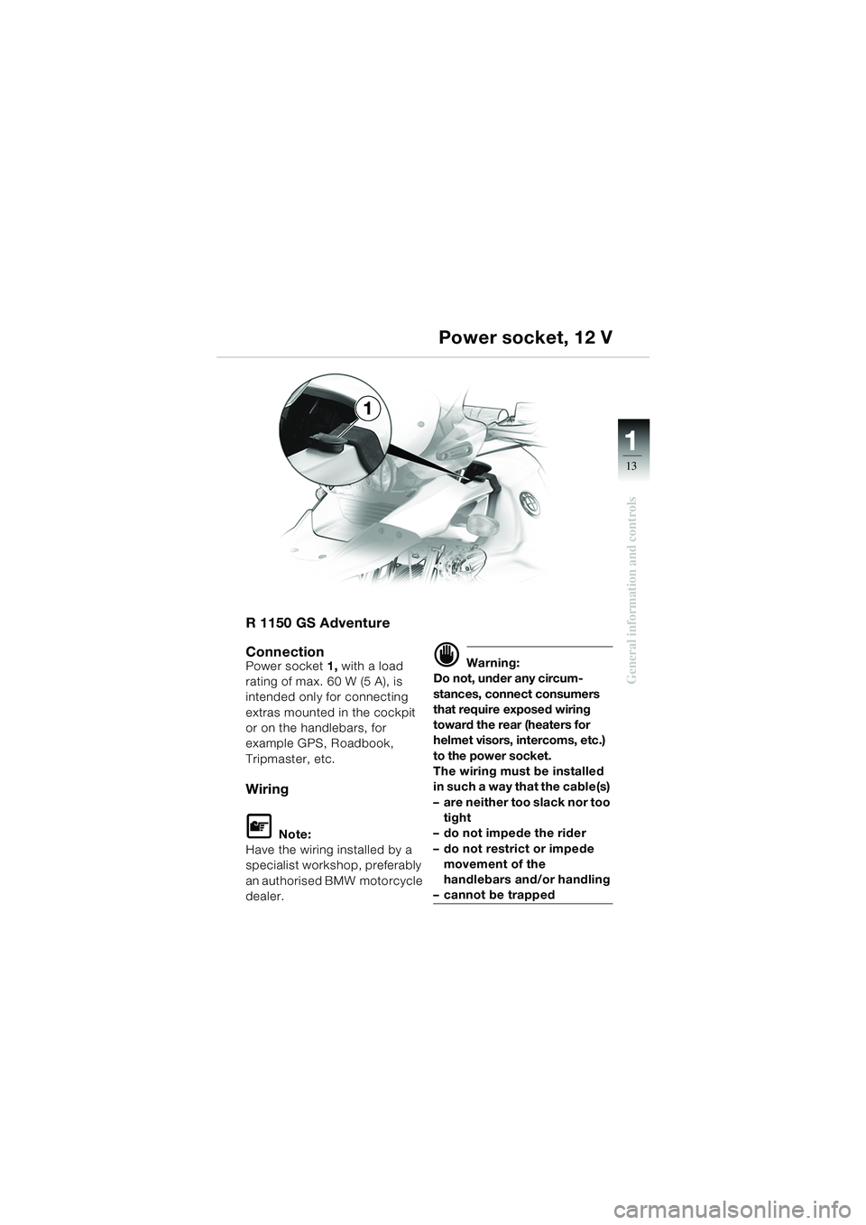
R 1150 GS Adventure
Connection
Power socket 1, with a load
rating of max. 60 W (5 A), is
intended only for connecting
extras mounted in the cockpit
or on the handlebars, for
example GPS, Roadbook,
Tripmaster, etc.
Wiring
L Note:
Have the wiring installed by a
specialist workshop, preferably
an authorised BMW motorcycle
dealer.
d Warning:
Do not, under any circum-
stances, connect consumers
that require exposed wiring
toward the rear (heaters for
helmet visors, intercoms, etc.)
to the power socket.
The wiring must be installed
in such a way that the cable(s)
– are neither too slack nor too tight
– do not impede the rider
– do not restrict or impede movement of the
handlebars and/or handling
– cannot be trapped
Power socket, 12 V
10geBKg6.book Seite 13 Dienstag, 19. November 2002 1:11 13
Page 16 of 104
11
14
General information and controls
1
23
4
5
d Warning:
To prevent air from entering
the clutch system:
do not turn the fitting on the
handlebar.
do not turn the handlebars
in the clamping blocks.
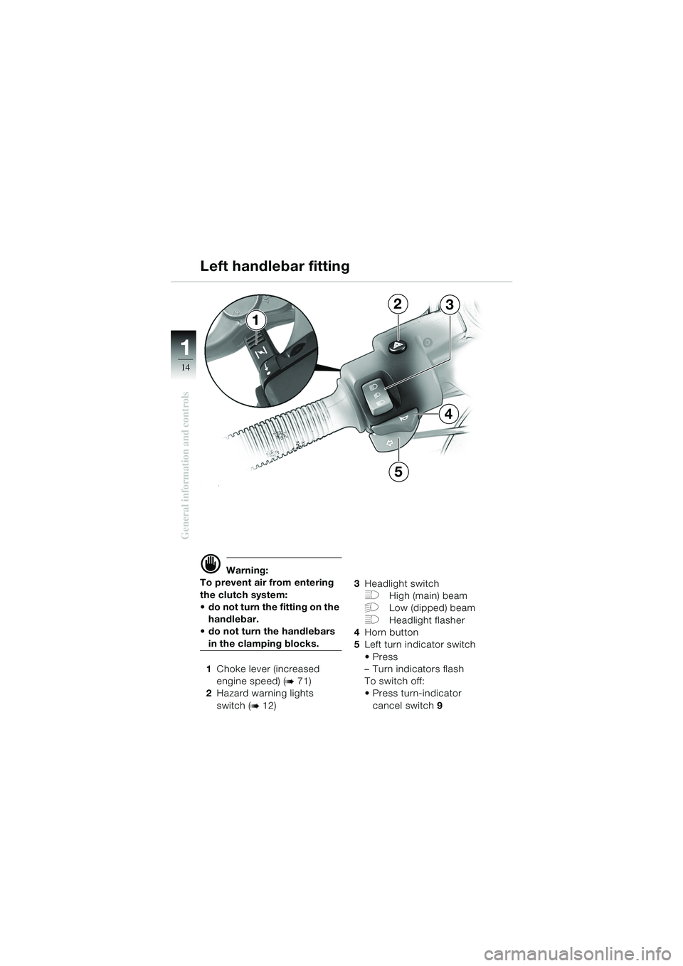
1 Choke lever (increased
engine speed) (
b71)
2 Hazard warning lights
switch (
b12) 3
Headlight switch
FHigh (main) beam
GLow (dipped) beam
FHeadlight flasher
4 Horn button
5 Left turn indicator switch
Press
–Turn indicators flash
To switch off:
Press turn-indicator
cancel switch 9
Left handlebar fitting
10geBKg6.book Seite 14 Dienstag, 19. November 2002 1:11 13
Page 17 of 104
111
15
General information and controlsd Warning:
To prevent air from entering
the brake system:
do not turn the fitting on the handlebar.
do not turn the handlebars
in the clamping blocks.
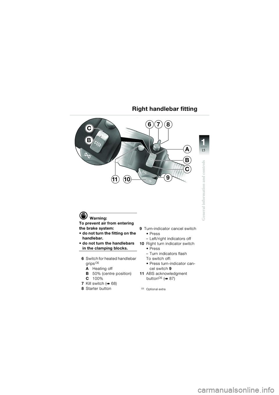
6 Switch for heated handlebar
grips
OE
A Heating off
B 50% (centre position)
C 100%
7 Kill switch (
b68)
8 Starter button 9
Turn-indicator cancel switch
Press
– Left/right indicators off
10 Right turn indicator switch
Press
– Turn indicators flash
To switch off:
Press turn-indicator can-
cel switch 9
11 ABS acknowledgment
button
OE (b87)
OEOptional extra
Right handlebar fitting
7
B
C
A
68
910
C
11
B
10geBKg6.book Seite 15 Dienstag, 19. November 2002 1:11 13
Page 18 of 104
11
16
General information and controls
Dualseat
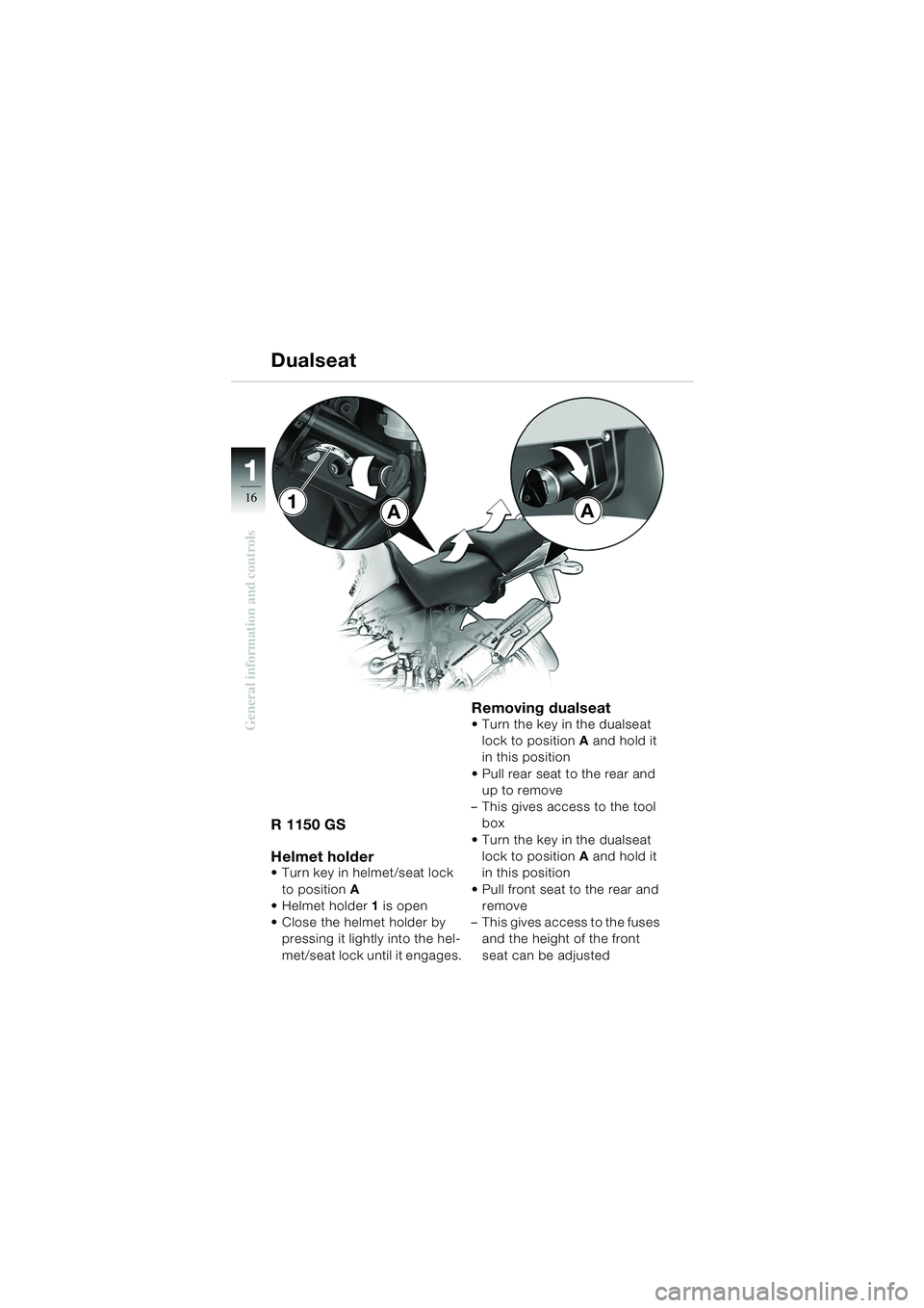
R 1150 GS
Helmet holder
Turn key in helmet/seat lock to position A
Helmet holder 1 is open
Close the helmet holder by pressing it lightly into the hel-
met/seat lock until it engages.
Removing dualseat Turn the key in the dualseat lock to position A and hold it
in this position
Pull rear seat to the rear and up to remove
– This gives access to the tool box
Turn the key in the dualseat lock to position A and hold it
in this position
Pull front seat to the rear and remove
– This gives access to the fuses and the height of the front
seat can be adjusted
AA1
10geBKg6.book Seite 16 Dienstag, 19. November 2002 1:11 13
Page 19 of 104
111
17
General information and controls
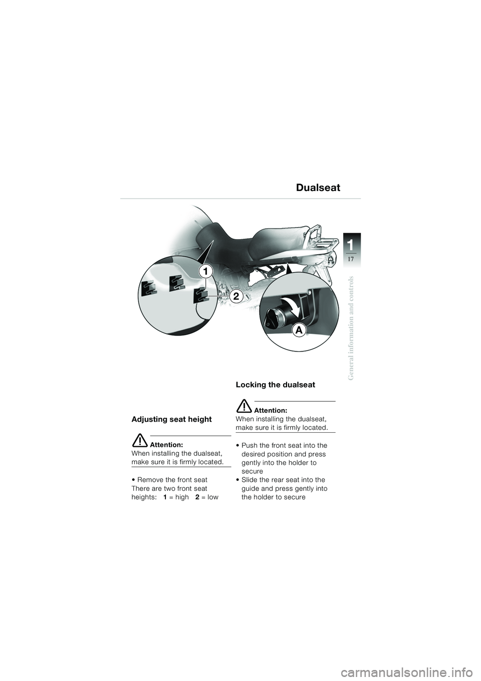
Adjusting seat height
e Attention:
When installing the dualseat,
make sure it is firmly located.
Remove the front seat
There are two front seat
heights: 1 = high 2 = low
Locking the dualseat
e Attention:
When installing the dualseat,
make sure it is firmly located.
Push the front seat into the
desired position and press
gently into the holder to
secure
Slide the rear seat into the
guide and press gently into
the holder to secure
Dualseat
A
1
2
10geBKg6.book Seite 17 Dienstag, 19. November 2002 1:11 13
Page 20 of 104
11
18
General information and controls
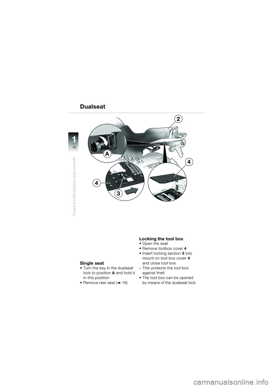
Single seat Turn the key in the dualseat lock to position A and hold it
in this position
Remove rear seat (
b16)
Locking the tool boxOpen the seat
Remove toolbox cover 4
Insert locking section 3 into
mount on tool box cover 4
and close tool box
– This protects the tool box
against theft
The tool box can be opened
by means of the dualseat lock
A
Dualseat
4
4
2
3
10geBKg6.book Seite 18 Dienstag, 19. November 2002 1:11 13