display BUICK LESABRE 2003 Owner's Manual
[x] Cancel search | Manufacturer: BUICK, Model Year: 2003, Model line: LESABRE, Model: BUICK LESABRE 2003Pages: 380, PDF Size: 2.75 MB
Page 73 of 380
Door Ajar Reminder
If your vehicle is equipped with the Driver Information
Center (DIC), and a door is not fully closed, the DIC will
display a DOOR AJAR message. See
Driver Information
Center (DIC) on page 3-45.
Delayed Locking
This feature lets the driver delay the actual locking of
the vehicle. When the driver's power door lock switch or
remote keyless entry lock button is pressed with the
key removed from the ignition, and the driver's
door open, a chime will sound three times to signal that
the delayed locking system is active. When all doors
have been closed, the doors will lock automatically after
®ve seconds. If any door is opened before this, the
®ve-second timer will reset itself once all the doors have
been closed again.
Pressing the driver's or passenger's power door lock
switch or the remote keyless entry transmitter button
again will override this feature.
Personal Choice Programming
The delayed locking feature can be turned on or off.
If your vehicle is equipped with the DIC, you must use it
to program this feature. See
Driver Information Center
(DIC) on page 3-45.To turn the feature on, do the following:
1. Close all the doors and turn the ignition on. Keep
all doors closed throughout this procedure.
2. Press and hold LOCK on the driver's power door
lock switch throughout this procedure. All the
doors will lock.
3. Press the unlock button on the transmitter. The lock
delay is still off and all doors will remain locked.
4. Press the unlock button on the transmitter again.
Lock delay is now active and all doors will unlock.
5. Release the power door lock switch.
To turn this feature off, repeat the previous procedure.
This procedure only changes the mode for the
transmitter used to change this setting.
Programmable Automatic
Door Locks
Close the doors and turn on the ignition. Every time you
move the shift lever out of PARK (P), all of the doors
will lock. And, every time you stop and move the
shift lever into PARK (P), the doors will unlock. If
someone needs to get out while you're not in PARK (P),
have that person use the manual door lock control or
power door lock switch. When the door is closed again,
it will not lock automatically. If you need to lock the
doors before shifting out of PARK (P), use the manual
door lock control or power door lock switch.
2-11
Page 84 of 380

Ignition Positions
With the key in the ignition switch, you can turn it to ®ve
different positions.
(A) ACCESSORY:This position lets you use your
electrical accessories such as power windows, power
sunroof (if equipped), radio and the windshield wipers.
To use, push in the ignition key and turn it toward
you. Your steering wheel will remain locked, just as it
was before you inserted the key.
(B) LOCK:This is the only position in which you can
remove the key. This position locks your ignition,
steering wheel and transaxle. It's a theft-deterrent
feature.
Notice:If your key seems stuck in LOCK and you
can't turn it, be sure you are using the correct key; if
so, is it all the way in? If it is, then turn the steering
wheel left and right while you turn the key hard.
Turn the key only with your hand. Using a tool
to force it could break the key or the ignition switch.
If none of these works, then your vehicle needs
service.
(C) OFF:This position lets you turn off the engine but
still turn the steering wheel. It doesn't lock the
steering wheel like LOCK and it doesn't send any
electrical power to the accessories. The instrument
panel cluster will remain powered in LOCK to illuminate
the gear shift indicator. The cluster will also activate
the parking brake light when the parking brake is
set. Use OFF if you must have your vehicle in motion
while the engine is not running.
(D) RUN:This is the position the switch returns to after
you start your engine and release the switch. This is
also the position for normal driving. Even when the
engine is not running, you can use RUN to operate your
electrical accessories and to display some instrument
panel warning lights.
(E) START:This position starts your engine. When the
engine starts, release the key. The ignition switch
will return to RUN for normal driving.
2-22
Page 95 of 380

Mirrors
Manual Rearview Mirror
When you are sitting in a comfortable driving position,
adjust the mirror so you can see clearly behind your
vehicle. Grip the mirror in the center to move it up
or down and side to side. The day/night adjustment
allows you to adjust the mirror to avoid glare from any
headlamps behind you. Push the tab away from
you for daytime use; pull it toward you for night use.
Automatic Dimming Rearview Mirror
Your vehicle may have an automatic dimming rearview
mirror. Your vehicle's mirror may also contain OnStarž
controls. SeeOnStaržSystem on page 2-37for
more information.
At night, when the glare is too high, the mirror will
gradually darken to reduce glare. This change may take
a few seconds. The mirror will return to its clear
daytime state when the glare is reduced.
Mirror Operation
AUTO:Press this button to turn on the automatic
dimming feature.
OFF:Press this button to turn off the automatic
dimming feature.
O(On/Off):For mirrors equipped with OnStarž
controls, press this button to turn on the automatic
dimming feature. To turn off automatic dimming, press
this button again.
The indicator light will be illuminated when this feature
is active.
Automatic Dimming Rearview Mirror
with Compass
Your vehicle may have an automatic dimming rearview
mirror with a compass. Your vehicle's mirror may
also contain OnStar
žcontrols. SeeOnStaržSystem on
page 2-37for more information.
The mirror also includes an eight-point compass display
in the upper right corner of the mirror face.
When cleaning the mirror, use a paper towel or similar
material dampened with glass cleaner. Do not spray
glass cleaner directly on the mirror as that may cause
the liquid cleaner to enter the mirror housing.
2-33
Page 96 of 380

Mirror Operation
MIRROR:Press this button to turn on the automatic
dimming feature. Press it again to turn off the automatic
dimming feature.
O(On/Off):For mirrors equipped with OnStarž
controls, press and hold this button for several seconds
to turn on the automatic dimming feature. Press and
hold it again to turn the automatic dimming feature off.
The green indicator light will come on when this
feature is active. The automatic dimming feature will be
active each time the vehicle is started.
Compass Operation
COMPASS:Press this button once to turn the compass
on or off.
O(On/Off):For mirrors equipped with OnStarž
controls, press this button once to turn the compass on
or off.
When the ignition and the compass feature are on, the
compass will show two character boxes for
approximately two seconds. After two seconds, the
mirror will display the compass heading.
Compass Calibration
When on, the compass automatically calibrates as the
vehicle is driven. If, after two seconds, the display
does not show a compass heading (N for North, forexample), there may be a strong magnetic ®eld
interfering with the compass. Such interference may be
caused by a magnetic antenna mount, magnetic
note pad holder or a similar magnetic item. If the letter
C should ever appear in the compass window, the
compass may need calibration.
The mirror can be calibrated by driving the vehicle in
circles at 5 mph (8 km/h) or less until the display reads a
direction.
Mirrors equipped with OnStar
žcontrols can be placed
in calibration mode by pressing and holding the
on/off button untilaCisshown in the compass display.
Compass Variance
Compass variance is the difference between earth's
magnetic north and true geographic north. The mirror is
set in zone eight upon leaving the factory. It will be
necessary to adjust the compass to compensate
for compass variance if you live outside zone eight.
Under certain circumstances, as during a long distance
cross-country trip, it will be necessary to adjust for
compass variance. If not adjusted to account for
compass variance, your compass could give false
readings.
To adjust for compass variance, do the following:
1. Find your current location and variance zone
number on the following zone map.
2-34
Page 97 of 380

2. Press and hold COMPASS (or the on/off button for
mirrors equipped with OnStaržcontrols) until a
zone number appears in the display.
3. Once a zone number appears in the display, press
the COMPASS button (or the on/off button for
mirrors equipped with OnStar
žcontrols) quickly until
the correct zone number appears in the display.
Stop pressing the button and the mirror will return to
normal operation. If C appears in the compass
window, the compass may need calibration. See
ªCompass Calibrationº explained previously.
Outside Power Mirrors
The controls for the
outside power mirrors are
located on the driver's
door armrest.
Press the left or right side of the L/R selector switch
located beneath the control pad to choose the left
or right mirror.
To adjust the mirror, press one of the four arrows
located on the control pad to move the mirror in the
direction you want it to go. When ®nished adjusting the
mirrors, leave the L/R selector switch in the center
position, to prevent unwanted mirror movement in case
the control pad is accidentally bumped while driving.
Adjust each outside mirror so that you can see a little of
your vehicle, and the area behind your vehicle.
2-35
Page 107 of 380
2. Adjust the driver's seat and lumbar position to a
safe and comfortable driving position. Adjust both
outside mirrors to suit you. See
Outside Power
Mirrors on page 2-35.
3. Press and hold the MEMORY button (1 or 2)
corresponding with your DRIVER # displayed on the
DIC for longer than three seconds. You will hear
two beeps con®rming that the seat and mirror
positions have been entered into memory.
To set the seat and mirror positions for a second driver,
follow the previous steps, but start by pressing the
unlock button on the transmitter that displays the other
DRIVER # on the DIC. Be sure to use the MEMORY
button which corresponds to the DRIVER # identi®ed by
the second transmitter.
To recall your memory positions, your vehicle must be
in PARK (P). Push and release the MEMORY button
corresponding to the desired driving position. The seat
and mirrors will move to the position previously
stored for the identi®ed driver. You will hear one beep.
To store the exit position for an easy exit, use the
following procedure:
1. First identify the DRIVER # by pressing the
MEMORY button 1 or 2 or by pressing the unlock
button on the transmitter.
2. Adjust the driver's seat to the desired exit position.3. Press and hold the EXIT button for longer than
three seconds. You will hear two beeps con®rming
that the seat exit position has been entered into
memory.
To set the exit position for a second driver, follow the
previous steps, but start by pressing the unlock
button on the transmitter that displays the other
DRIVER # on the DIC. Be sure to use the MEMORY
button which corresponds to the DRIVER # identi®ed by
the other transmitter.
To recall the exit position, your vehicle must be in
PARK (P). Push and release the EXIT button and the
seat will move to the exit position previously stored
for the current identi®ed driver. You will hear one beep.
If an exit position has not been stored for the current
identi®ed driver, the seat will move all the way back.
To stop recall movement of the seat at any time, press
the driver's power seat control located on the outboard
side of the front seat.
Mirrors and lumbar positions will not be stored or
recalled for the exit position.
If you would like your stored driving or exit position to
be recalled when unlocking your vehicle with the
transmitter, see
DIC Vehicle Personalization on
page 3-50.
2-45
Page 109 of 380
Instrument Panel Overview...............................3-4
Hazard Warning Flashers................................3-6
Other Warning Devices...................................3-6
Horn.............................................................3-7
Tilt Wheel.....................................................3-7
Turn Signal/Multifunction Lever.........................3-7
Exterior Lamps.............................................3-14
Interior Lamps..............................................3-17
Head-Up Display (HUD).................................3-20
Accessory Power Outlets...............................3-22
Ashtrays and Cigarette Lighter........................3-23
Climate Controls............................................3-24
Climate Control System.................................3-24
Dual Automatic Climate Control System...........3-26
Outlet Adjustment.........................................3-30
Steering Wheel Climate Controls.....................3-31
Climate Controls Personalization.....................3-31
Warning Lights, Gages and Indicators.............3-32
Instrument Panel Cluster................................3-33
Speedometer and Odometer...........................3-35
Tachometer.................................................3-35
Safety Belt Reminder Light.............................3-36Air Bag Readiness Light................................3-36
Battery Warning Light....................................3-37
Brake System Warning Light..........................3-37
Anti-Lock Brake System Warning Light.............3-38
Traction Control System (TCS) Warning Light . . .3-39
Engine Coolant Temperature Gage..................3-40
Malfunction Indicator Lamp.............................3-40
Oil Pressure Light.........................................3-43
Security Light...............................................3-44
Cruise Control Light......................................3-44
Service Vehicle Soon Light............................3-44
Fuel Gage...................................................3-45
Driver Information Center (DIC).......................3-45
DIC Controls and Displays.............................3-46
DIC Warnings and Messages.........................3-49
DIC Vehicle Personalization............................3-50
Audio System(s).............................................3-55
Setting the Time...........................................3-55
Radio with CD..............................................3-56
Radio with Cassette and CD..........................3-62
Trunk-Mounted CD Changer...........................3-73
Personal Choice Radio Controls......................3-77
Section 3 Instrument Panel
3-1
Page 113 of 380
The main components of your instrument panel are the following:
A. Air Outlets
B. Driver Information Center (DIC) Buttons (If Equipped)
C. Turn Signal/Multifunction Lever
D. Steering Wheel Controls (If Equipped)
E. Hazard Warning Flashers
F. Instrument Panel Cluster
G. Traction Control Button (If Equipped)
H. Exterior Lamp ButtonsI. Head-Up Display (HUD) Controls (If Equipped)
J. Hood Release
K. Parking Brake
L. Cruise Controls
M. Audio System
N. Climate Controls
O. Glove Box
3-5
Page 116 of 380
Turn and Lane-Change Signals
To signal a turn, move the lever on the left side of the
steering wheel all the way up or down. The lever returns
automatically when the turn is complete.
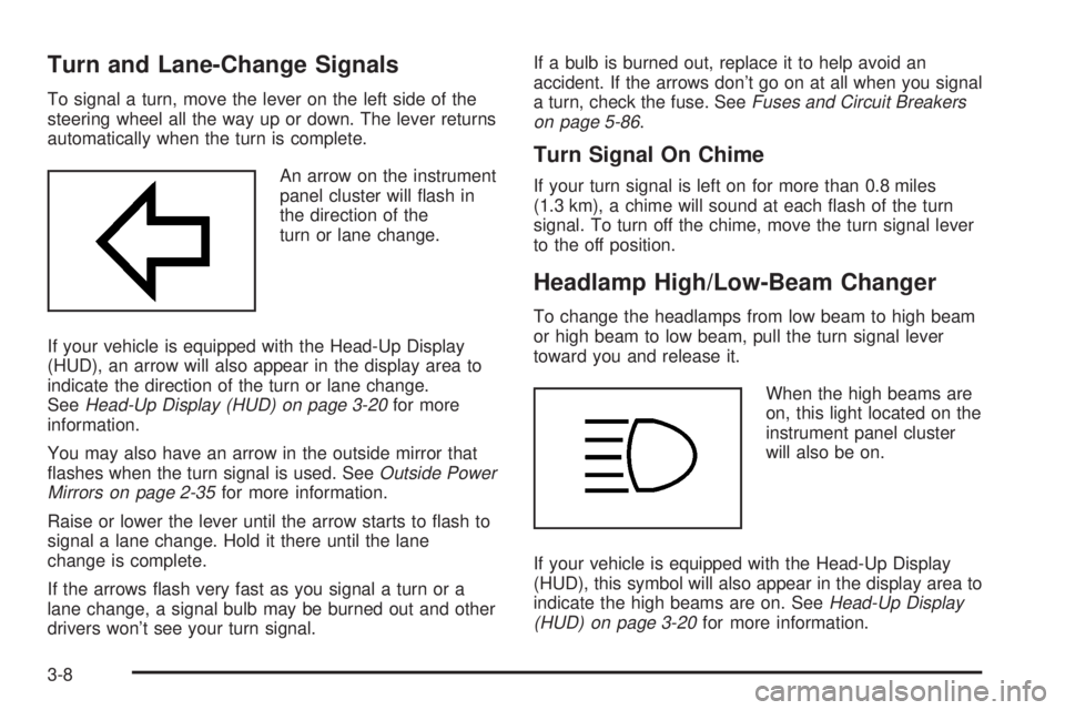
An arrow on the instrument
panel cluster will ¯ash in
the direction of the
turn or lane change.
If your vehicle is equipped with the Head-Up Display
(HUD), an arrow will also appear in the display area to
indicate the direction of the turn or lane change.
See
Head-Up Display (HUD) on page 3-20for more
information.
You may also have an arrow in the outside mirror that
¯ashes when the turn signal is used. See
Outside Power
Mirrors on page 2-35for more information.
Raise or lower the lever until the arrow starts to ¯ash to
signal a lane change. Hold it there until the lane
change is complete.
If the arrows ¯ash very fast as you signal a turn or a
lane change, a signal bulb may be burned out and other
drivers won't see your turn signal.If a bulb is burned out, replace it to help avoid an
accident. If the arrows don't go on at all when you signal
a turn, check the fuse. See
Fuses and Circuit Breakers
on page 5-86.
Turn Signal On Chime
If your turn signal is left on for more than 0.8 miles
(1.3 km), a chime will sound at each ¯ash of the turn
signal. To turn off the chime, move the turn signal lever
to the off position.
Headlamp High/Low-Beam Changer
To change the headlamps from low beam to high beam
or high beam to low beam, pull the turn signal lever
toward you and release it.
When the high beams are
on, this light located on the
instrument panel cluster
will also be on.
If your vehicle is equipped with the Head-Up Display
(HUD), this symbol will also appear in the display area to
indicate the high beams are on. See
Head-Up Display
(HUD) on page 3-20for more information.
3-8
Page 128 of 380
Battery Load Management
The battery load management feature is designed to
monitor the vehicle's electrical load and determine when
the battery is in a heavy discharge condition. During
times of high electrical loading, the engine may idle at a
higher rpm setting than normal to make sure the
battery charges. High electrical loads may occur when
several of the following are on: headlamps, high beams,
rear window defogger, fan at high speed, heated
seats (if equipped) and engine cooling fans.
If your vehicle's battery remains in a heavy discharge
condition for a long period of time, the fan, rear
defogger, heated seats and heated mirrors will be
disabled and the DIC will display BATTERY SAVER
ACTIVE. This can happen either under long periods of
idling or low speed driving with high electrical loading,
or in the event of a charging system fault.
Head-Up Display (HUD)
{CAUTION:
If the HUD image is too bright, or too high in
your ®eld of view, it may take you more time to
see things you need to see when it's dark
outside. Be sure to keep the HUD image dim
and placed low in your ®eld of view.
If your vehicle is equipped with the Head-Up Display
(HUD), you can see some of the driver information that
appears on your instrument panel cluster.
The information may be displayed in English or metric
units and appears as a re¯ection in the windshield.
The HUD consists of the following information:
·Speedometer Reading
·Turn Signal Indicators
·High-Beam Headlamp Indicator
·Check Gages Message
3-20