sensor CHERY TIGGO 2009 Service Repair Manual
[x] Cancel search | Manufacturer: CHERY, Model Year: 2009, Model line: TIGGO, Model: CHERY TIGGO 2009Pages: 1903, PDF Size: 33.38 MB
Page 505 of 1903

Downloaded from www.Manualslib.com manuals search engine Operation
When engine is running, the high and low parts of the teeth causes the gap with the sensor to change. The changing
gap causes the magnetic field near the sensor to change. Due to the changing magnetic field, the voltage from the
sensor changes. The Engine Control Module (ECM) detects the voltage signal and identify piston position and cyl-
inder timing.
Removal & Installation
1. Disconnect the negative battery cable.
2. Disconnect the CMP sensor electrical connector.
3. Remove the CMP sensor (1) retaining bolt.(Tighten: Camshaft position sensor retaining bolt to
7 N·m)
4. Pull the CMP sensor up and take out of the cylin- der head cover.
5. Installation is in the reverse order of removal.
Vehicle Speed Sensor
Description
The vehicle speed sensor is mounted to the transaxle housing.
Operation
The vehicle speed sensor generates a signal sent to the Engine Control Module (ECM) and the Transaxle Control
Module (TCM) utilize to perform engine and transaxle functions.
Removal & Installation
1. Disconnect the negative battery cable.
2. Disconnect the vehicle speed sensor connector.
3. Remove the vehicle speed sensor mounting bolt (1).
(Tighten: Vehicle speed sensor mounting bolt to 10
N·m)
4. Remove the vehicle speed sensor carefully.
5. Installation is in the reverse order of removal.
Accelerator Sensor
Description
The accelerator sensor is located on the right front crossbeam.
ON-VEHICLE SERVICE
BESM030016
BESM030024
03
03–221Chery Automobile Co., Ltd.
Page 506 of 1903

Downloaded from www.Manualslib.com manuals search engine Operation
The accelerator sensor monitors the road conditions. It sends a signal to the ECM, the ECM determines if a possible
misfire condition exists.
Removal & Installation
1. Disconnect the negative battery cable.
2. Disconnect the accelerator sensor electrical con-nector.
3. Remove the accelerator sensor (1).
4. Installation is in the reverse order of removal.
Manifold Absolute Pressure Sensor - 1.6L
Description
The Manifold Absolute Pressure (MAP) sensor, is mounted to the front of the engine on the intake manifold.
Operation
The MAP sensor monitors the pressure in the intake manifold. The pressure in the manifold moves a diaphragm
connected to resistors which alter their resistance values. The output voltage of the MAP sensor signals the ECM
about the pressure in the intake manifold.
Removal & Installation
1. Disconnect the negative battery cable.
ON-VEHICLE SERVICE
LTSM030030
03–222Chery Automobile Co., Ltd.
Page 507 of 1903

Downloaded from www.Manualslib.com manuals search engine 2. Disconnect the MAP sensor electrical connector.
3. Remove the MAP sensor mounting bolt (1).(Tighten: MAP sensor mounting bolt to 6 N·m)
4. Remove the MAP sensor.
5. Installation is in the reverse order of removal.
Air Flow Sensor - 1.8L
Description
The air flow sensor is placed in the air intake hose. The air flow sensor measures the intake flow rate by measuring
a part of the entire intake flow. The air flow sensor converts the amount of air drawn into the engine into a voltage
signal. The Engine Control Module (ECM) needs to know intake air volume to calculate engine load. This is neces-
sary to determine how much fuel to inject.
Operation
The air flow sensor controls the temperature of the hot wire to a certain amount. The heat generated by the hot wire
is reduced as the intake air flows around it. The more air, the greater the heat loss. Therefore, the electric current
supplied to the hot wire is changed to maintain the temperature of the hot wire as air flow increases. The ECM
detects the air flow by means of this voltage signal change.
Removal & Installation
1. Disconnect the negative battery cable.
2. Remove the engine cover.
3. Disconnect the air flow sensor electrical connector.
ON-VEHICLE SERVICE
LTSM030037
03
03–223Chery Automobile Co., Ltd.
Page 508 of 1903

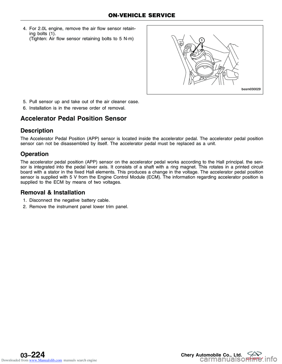
Downloaded from www.Manualslib.com manuals search engine 4. For 2.0L engine, remove the air flow sensor retain-ing bolts (1).
(Tighten: Air flow sensor retaining bolts to 5 N·m)
5. Pull sensor up and take out of the air cleaner case.
6. Installation is in the reverse order of removal.
Accelerator Pedal Position Sensor
Description
The Accelerator Pedal Position (APP) sensor is located inside the accelerator pedal. The accelerator pedal position
sensor can not be disassembled by itself. The accelerator pedal must be replaced as a unit.
Operation
The accelerator pedal position (APP) sensor on the accelerator pedal works according to the Hall principal. the sen-
sor is integrated into the pedal lever axis. It consists of a shaft with a ring magnet. This rotates in a printed circuit
board with a stator in the fixed Hall elements. This produces a change in the voltage. The accelerator pedal position
sensor is supplied with 5 V from the Engine Control Module (ECM). The information regarding accelerator position is
supplied to the ECM by means of two voltages.
Removal & Installation
1. Disconnect the negative battery cable.
2. Remove the instrument panel lower trim panel.
ON-VEHICLE SERVICE
BESM030029
03–224Chery Automobile Co., Ltd.
Page 509 of 1903

Downloaded from www.Manualslib.com manuals search engine 3. Disconnect the APP sensor electrical connector (2).
4. Remove the three APP sensor mounting bolts (1).(Tighten: APP sensor mounting bolts to 11 N·m)
5. Remove the APP sensor with the pedal.
6. Installation is in the reverse order of removal.
Electronic Throttle Control Actuator
Description
The throttle body is located on the intake manifold. It controls air into the intake manifold. The electronic throttle
control actuator consists of throttle control motor, throttle position sensor, etc. The throttle control motor is operated
by the Engine Control Module (ECM) and it opens and closes the throttle valve. The throttle position sensor detects
the throttle valve position.
Operation
Filtered air from the air cleaner enters the intake manifold through the throttle body. A throttle valve (plate) is used to
supply air for idle and driving conditions. The throttle position sensor is part the throttle body. The throttle position
sensor signal is used by the ECM to determine throttle position. The ECM controls the electronic throttle control to
meter air into the engine. This regulates engine power. The vehicle is in sense a “Drive by Wire” system.
Removal & Installation
1. Remove the engine cover.
2. Disconnect the negative battery cable.
ON-VEHICLE SERVICE
LTSM030038
03
03–225Chery Automobile Co., Ltd.
Page 511 of 1903

Downloaded from www.Manualslib.com manuals search engine 2.0L ENGINE CONTROLS
GENERAL INFORMATION03-229
Description 03-229
Operation 03-229
Electronic Engine Control Input & Output
Device Failure Modes 03-230
Specifications 03-231
Special Tools 03-232
Electrical Schematics 03-234
ECM Connector Pin-Out Table 03-245
DIAGNOSIS & TESTING03-247
Diagnostic Help 03-247
Ground Inspection 03-247
Electronic Throttle Control Actuator
Self-Learning Operation Introduction 03-247
Diagnostic Tools 03-248
Diagnostic Trouble Code (DTC) List 03-250
ECM Power Supply and Ground Circuit
Test 03-254
Power Supply And Ground Circuit
Diagnostic Check 03-254
Diagnostic Trouble Code (DTC) Tests 03-261
P0016 - Camshaft Position-Crankshaft
Position Correlation Error 03-261
P0031 - O
2Sensor 1 Heater Control
Circuit Low 03-272
P0032 - O
2Sensor 1 Heater Control
Circuit High 03-277
P0102 - Mass Or Volume Air Flow
Circuit Low Input 03-282
P0103 - Mass Or Volume Air Flow
Circuit High Input 03-288
P0112 - Intake Air Temperature Circuit
Low Input 03-293
P0113 - Intake Air Temperature Circuit
High Input 03-297
P0117 - Engine Coolant Temperature
Circuit Low Input 03-301
P0118 - Engine Coolant Temperature
Circuit High Input 03-305
P0122 - Throttle Position Sensor A
Circuit Low Input 03-310
P0123 - Throttle Position Sensor A
Circuit High Input 03-316
P0132 - O
2Sensor Circuit 1 High
Voltage 03-322
P0171 - Fuel Trim System Too Lean 03-326
P0172 - Fuel Trim System Too Rich 03-336
P0201 - Cylinder 1 - Injector Circuit,
P0202 - Cylinder 2 - Injector Circuit,
P0203 - Cylinder 3 - Injector Circuit,
P0204 - Cylinder 4 - Injector Circuit 03-345
P0221 - Throttle Position Sensor B
Performance 03-352 P0261 - Cylinder 1 Injector Circuit Low,
P0264 - Cylinder 2 Injector Circuit Low,
P0267 - Cylinder 3 Injector Circuit Low,
P0270 - Cylinder 4 Injector Circuit Low 03-359
P0262 - Cylinder 1 Injector Circuit High,
P0265 - Cylinder 2 Injector Circuit High,
P0268 - Cylinder 3 Injector Circuit High,
P0271 - Cylinder 4 Injector Circuit High 03-366
P0321 - Distributor Engine Speed In
Phase Circuit Performance 03-373
P0324 - Knock Control System Error 03-378
P0343 - Camshaft Position Sensor
Circuit High Input 03-383
P0444 - Evaporative Emission System
Purge Control Valve Circuit Open 03-389
P0506 - Idle Control System RPM
Lower Than Expected 03-394
P0604 - Internal Controller Module
Random Access Memory (RAM) Error,
P0605 - Internal Controller Module
ROM Test Error, P0606 - ECM
Processor 03-396
P0602 - ECM Programming Error 03-398
P0645 - A/C Clutch Relay Circuit 03-400
P1545 - Throttle Position Control
Performance 03-405
P2138 - Pedal Position Sensor
Performance 03-413
U0001 - High Speed CAN Defective 03-420
ON-VEHICLE SERVICE03-427
Engine Coolant Temperature (ECT)
Sensor 03-427
Description 03-427
Operation 03-427
Removal & Installation 03-427
Knock Sensor 03-428
Description 03-428
Operation 03-428
Removal & Installation 03-428
Oxygen Sensor 03-428
Description 03-428
Operation 03-428
Upstream Oxygen Sensor 03-429
Downstream Oxygen Sensor 03-429
Removal & Installation - Upstream
Oxygen Sensor 03-429
Removal & Installation - Downstream
Oxygen Sensor 03-429
Crankshaft Position (CKP) Sensor 03-430
Description 03-430
Operation 03-430
Removal & Installation 03-430
03
03–227Chery Automobile Co., Ltd.
Page 512 of 1903

Downloaded from www.Manualslib.com manuals search engine Camshaft Position (CMP) Sensor03-431
Description 03-431
Operation 03-431
Removal & Installation 03-431
Air Flow Sensor 03-431
Description 03-431
Operation 03-431
Removal & Installation 03-431
Accelerator Sensor 03-432
Description 03-432
Operation 03-432
Removal & Installation 03-432
Speed Control System 03-432
Description 03-432
Operation 03-433
Electrical Schematics 03-434Accelerator Pedal Position (APP)
Sensor
03-438
Description 03-438
Operation 03-438
Removal & Installation 03-438
Electronic Throttle Control Actuator 03-439
Description 03-439
Operation 03-439
Removal & Installation 03-439
Engine Control Module (ECM) 03-440
Description 03-440
Operation 03-440
Removal & Installation 03-440
ELECTRONIC ENGINE CONTROLS - 2.0L ENGINE CONTROLS
03–228Chery Automobile Co., Ltd.
Page 513 of 1903

Downloaded from www.Manualslib.com manuals search engine GENERAL INFORMATION
Description
The Engine Control Module (ECM) utilizes integrated circuitry and information carried on the Controller Area Network
(CAN) data bus along with many hard wired inputs to monitor many sensors and switches inputs throughout the
vehicle. In response to those inputs, the internal circuitry and programming of the ECM allow it to control and inte-
grate many electronic functions and features of the vehicle through both hard wired outputs and the transmission of
electronic message outputs to other electronic modules in the vehicle over the CAN data bus.
The following are the input and output components monitored by the ECM. The monitored functions include compo-
nents from the engine, ignition, transaxle, air conditioning, or any other ECM supported subsystem.
ECM Inputs
•Brake Switch Sensor
• A/C Pressure Switch
• Camshaft Position (CMP) Sensor
• Crankshaft Position (CKP) Sensor
• Engine Coolant Temperature (ECT) Sensor
• Intake Air Temperature (IAT) Sensor
• Air Flow Sensor
• Throttle Position Sensor (integral with Electronic Throttle Control Actuator)
• Power Steering Switch
• Accelerator Pedal Position (APP) Sensor
• Knock Sensor
• Oxygen Sensor (Upstream & Downstream)
• Clutch Pedal Switch (manual transaxle only)
ECM Outputs
• Canister Control Valve
• Fuel Injectors
• Fuel Pump Relay
• Electronic Throttle Control Actuator
• Ignition Coil
• A/C Compressor
• Cooling Fan
• Oxygen Sensor heating coil (Upstream & Downstream)
Operation
The ECM monitors components and circuits and tests them in various ways depending on the hardware, function,
and type of signal. For example, analog inputs such as throttle position or engine coolant temperature are typically
checked for opens, shorts and out-of-range values. This type of monitoring is carried out continuously. Some digital
inputs like vehicle speed or crankshaft position rely on rationality checks - checking to see if the input value makes
sense at the current engine operating conditions. These types of tests may require monitoring several components
and can only be carried out under appropriate test conditions.
The ECM is a pre-programmed, microprocessor-based digital computer. It regulates ignition timing, air-fuel ratio,
emission control devices, charging system, certain transmission features, speed control, air conditioning compressor
clutch engagement and idle speed. The ECM can adapt its programming to meet changing operating conditions.
03
03–229Chery Automobile Co., Ltd.
Page 514 of 1903

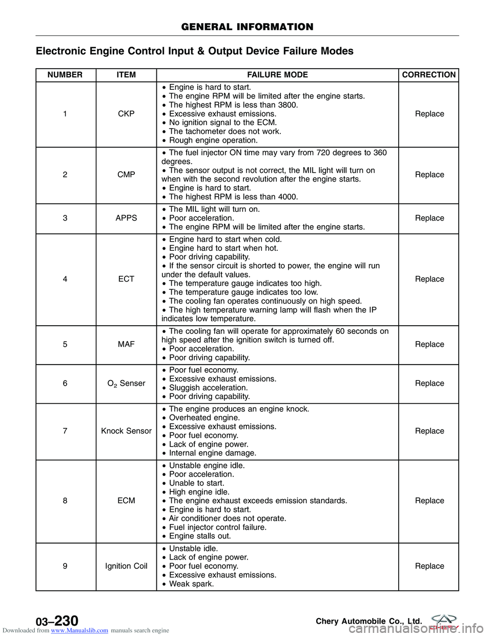
Downloaded from www.Manualslib.com manuals search engine Electronic Engine Control Input & Output Device Failure Modes
NUMBER ITEMFAILURE MODECORRECTION
1 CKP•
Engine is hard to start.
• The engine RPM will be limited after the engine starts.
• The highest RPM is less than 3800.
• Excessive exhaust emissions.
• No ignition signal to the ECM.
• The tachometer does not work.
• Rough engine operation. Replace
2 CMP•
The fuel injector ON time may vary from 720 degrees to 360
degrees.
• The sensor output is not correct, the MIL light will turn on
when with the second revolution after the engine starts.
• Engine is hard to start.
• The highest RPM is less than 4000. Replace
3 APPS•
The MIL light will turn on.
• Poor acceleration.
• The engine RPM will be limited after the engine starts. Replace
4 ECT•
Engine hard to start when cold.
• Engine hard to start when hot.
• Poor driving capability.
• If the sensor circuit is shorted to power, the engine will run
under the default values.
• The temperature gauge indicates too high.
• The temperature gauge indicates too low.
• The cooling fan operates continuously on high speed.
• The high temperature warning lamp will flash when the IP
indicates low temperature. Replace
5 MAF•
The cooling fan will operate for approximately 60 seconds on
high speed after the ignition switch is turned off.
• Poor acceleration.
• Poor driving capability. Replace
6O
2Senser •
Poor fuel economy.
• Excessive exhaust emissions.
• Sluggish acceleration.
• Poor driving capability. Replace
7 Knock Sensor •
The engine produces an engine knock.
• Overheated engine.
• Excessive exhaust emissions.
• Poor fuel economy.
• Lack of engine power.
• Internal engine damage. Replace
8 ECM•
Unstable engine idle.
• Poor acceleration.
• Unable to start.
• High engine idle.
• The engine exhaust exceeds emission standards.
• Engine is hard to start.
• Air conditioner does not operate.
• Fuel injector control failure.
• Engine stalls out. Replace
9 Ignition Coil •
Unstable idle.
• Lack of engine power.
• Poor fuel economy.
• Excessive exhaust emissions.
• Weak spark. Replace
GENERAL INFORMATION
03–230Chery Automobile Co., Ltd.
Page 515 of 1903

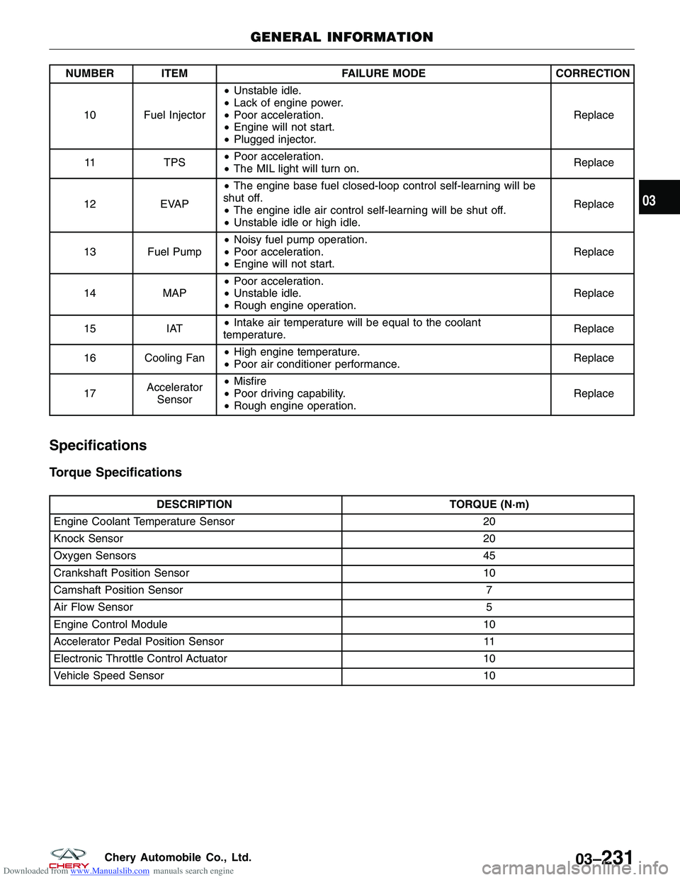
Downloaded from www.Manualslib.com manuals search engine NUMBER ITEMFAILURE MODECORRECTION
10 Fuel Injector •
Unstable idle.
• Lack of engine power.
• Poor acceleration.
• Engine will not start.
• Plugged injector. Replace
11 TPS•
Poor acceleration.
• The MIL light will turn on. Replace
12 EVAP•
The engine base fuel closed-loop control self-learning will be
shut off.
• The engine idle air control self-learning will be shut off.
• Unstable idle or high idle. Replace
13 Fuel Pump •
Noisy fuel pump operation.
• Poor acceleration.
• Engine will not start. Replace
14 MAP•
Poor acceleration.
• Unstable idle.
• Rough engine operation. Replace
15 IAT•
Intake air temperature will be equal to the coolant
temperature. Replace
16 Cooling Fan •
High engine temperature.
• Poor air conditioner performance. Replace
17 Accelerator
Sensor •
Misfire
• Poor driving capability.
• Rough engine operation. Replace
Specifications
Torque Specifications
DESCRIPTION
TORQUE (N·m)
Engine Coolant Temperature Sensor 20
Knock Sensor 20
Oxygen Sensors 45
Crankshaft Position Sensor 10
Camshaft Position Sensor 7
Air Flow Sensor 5
Engine Control Module 10
Accelerator Pedal Position Sensor 11
Electronic Throttle Control Actuator 10
Vehicle Speed Sensor 10
GENERAL INFORMATION
03
03–231Chery Automobile Co., Ltd.