CHERY TIGGO 2009 Service Repair Manual
Manufacturer: CHERY, Model Year: 2009, Model line: TIGGO, Model: CHERY TIGGO 2009Pages: 1903, PDF Size: 33.38 MB
Page 941 of 1903
Downloaded from www.Manualslib.com manuals search engine ON-VEHICLE SERVICE
Exhaust Pipe Assembly
Removal & Installation - 1.6L & 1.8L & 2.0L
WARNING!
The normal operating temperature of the exhaust system is very high. Therefore, never work around, or attempt
to service any part of the exhaust system until it has cooled. Special care should be taken when working near
the catalytic converter. The temperature of the converter rises to a high level after a short period of engine oper-
ating time.
1. Raise and support the vehicle.
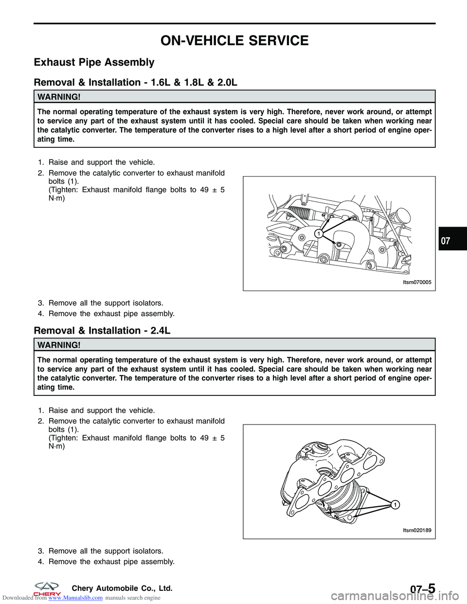
2. Remove the catalytic converter to exhaust manifoldbolts (1).
(Tighten: Exhaust manifold flange bolts to 49 ± 5
N·m)
3. Remove all the support isolators.
4. Remove the exhaust pipe assembly.
Removal & Installation - 2.4L
WARNING!
The normal operating temperature of the exhaust system is very high. Therefore, never work around, or attempt
to service any part of the exhaust system until it has cooled. Special care should be taken when working near
the catalytic converter. The temperature of the converter rises to a high level after a short period of engine oper-
ating time.
1. Raise and support the vehicle.
2. Remove the catalytic converter to exhaust manifold bolts (1).
(Tighten: Exhaust manifold flange bolts to 49 ± 5
N·m)
3. Remove all the support isolators.
4. Remove the exhaust pipe assembly.
LTSM070005
LTSM020189
07
07–5Chery Automobile Co., Ltd.
Page 942 of 1903
Downloaded from www.Manualslib.com manuals search engine Muffler
Removal & Installation
WARNING!
The normal operating temperature of the exhaust system is very high. Therefore, never work around, or attempt
to service any part of the exhaust system until it has cooled. Special care should be taken when working near
the catalytic converter. The temperature of the converter rises to a high level after a short period of engine oper-
ating time.
1. Raise and support the vehicle.
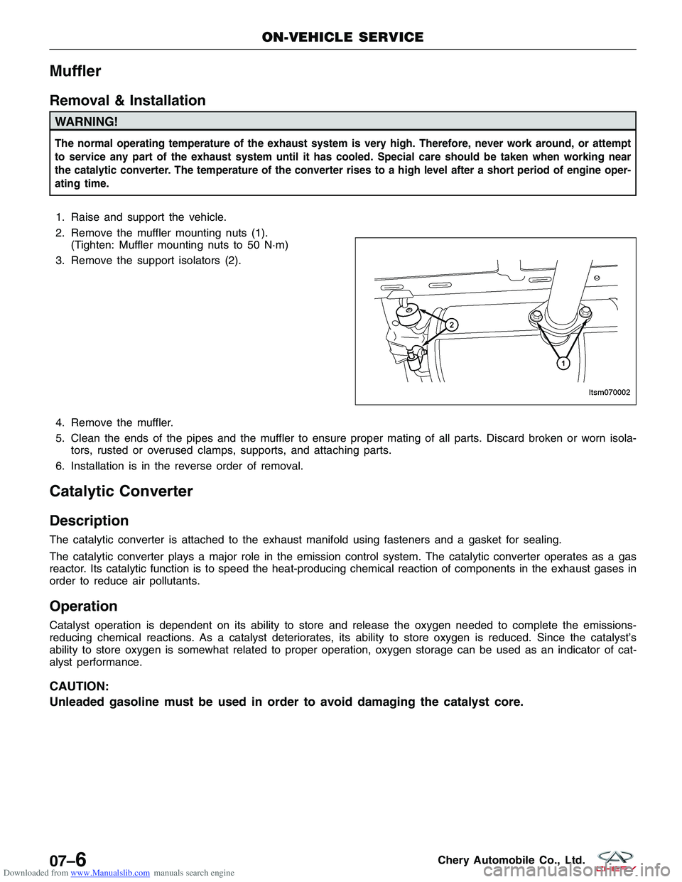
2. Remove the muffler mounting nuts (1).(Tighten: Muffler mounting nuts to 50 N·m)
3. Remove the support isolators (2).
4. Remove the muffler.
5. Clean the ends of the pipes and the muffler to ensure proper mating of all parts. Discard broken or worn isola- tors, rusted or overused clamps, supports, and attaching parts.
6. Installation is in the reverse order of removal.
Catalytic Converter
Description
The catalytic converter is attached to the exhaust manifold using fasteners and a gasket for sealing.
The catalytic converter plays a major role in the emission control system. The catalytic converter operates as a gas
reactor. Its catalytic function is to speed the heat-producing chemical reaction of components in the exhaust gases in
order to reduce air pollutants.
Operation
Catalyst operation is dependent on its ability to store and release the oxygen needed to complete the emissions-
reducing chemical reactions. As a catalyst deteriorates, its ability to store oxygen is reduced. Since the catalyst’s
ability to store oxygen is somewhat related to proper operation, oxygen storage can be used as an indicator of cat-
alyst performance.
CAUTION:
Unleaded gasoline must be used in order to avoid damaging the catalyst core.
ON-VEHICLE SERVICE
LTSM070002
07–6Chery Automobile Co., Ltd.
Page 943 of 1903
Downloaded from www.Manualslib.com manuals search engine Removal & Installation
WARNING!
The normal operating temperature of the exhaust system is very high. Therefore, never work around or attempt
to service any part of the exhaust system until it has cooled. Special care should be taken when working near
the catalytic converter. The temperature of the converter rises to a high level after a short period of engine oper-
ating time.
1. Disconnect the negative battery cable.
2. Raise and support the vehicle.
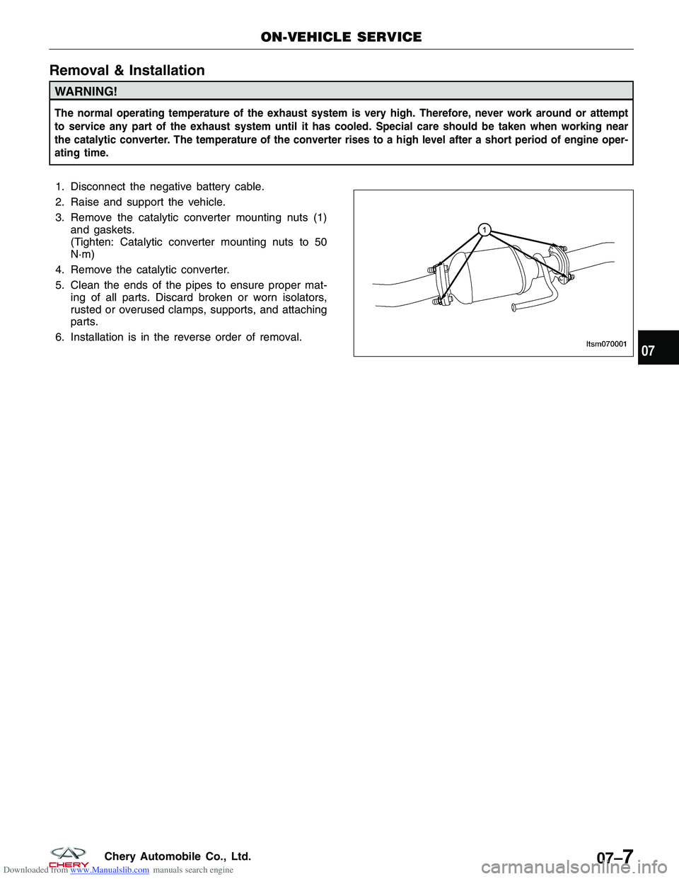
3. Remove the catalytic converter mounting nuts (1)and gaskets.
(Tighten: Catalytic converter mounting nuts to 50
N·m)
4. Remove the catalytic converter.
5. Clean the ends of the pipes to ensure proper mat- ing of all parts. Discard broken or worn isolators,
rusted or overused clamps, supports, and attaching
parts.
6. Installation is in the reverse order of removal.
ON-VEHICLE SERVICE
LTSM07000107
07–7Chery Automobile Co., Ltd.
Page 944 of 1903

Downloaded from www.Manualslib.com manuals search engine TRANSAXLE & TRANSFER CASE
08
CONTENTSpage
DP0 Automatic Transaxle .............................................................. 08-1
F4A4 Automatic Transaxle ........................................................... 08-143
5-Speed Manual Transaxle ........................................................... 08-246
Front Differential ................................................................... 08-307
Clutch System ..................................................................... 08-316
Transfer Case (4x4) ................................................................. 08-326
DP0 AUTOMATIC TRANSAXLE
GENERAL INFORMATION08-3
Description 08-3
Operation 08-6
Specifications 08-7
Special Tools 08-8
Electrical Schematics 08-10
DP0 Transaxle Control Module (TCM)
Connector Pin-Out Table 08-18
DIAGNOSIS & TESTING08-19
Diagnostic Help 08-19
Intermittent DTC Troubleshooting 08-19
Ground Inspection 08-19
Diagnostic Tools 08-19
Diagnostic Trouble Code (DTC) List 08-20
DP0 Automatic Transaxle DTC List 08-20
Diagnostic Trouble Code (DTC) Tests 08-22
P0641 - Sensor Feed 08-22
P0657 - Solenoid Power Supply Circuit
Shorted To Voltage 08-28
P0657 - Solenoid Power Supply Circuit
Open 08-32
P0705 - Multi-Function Switch:
Prohibited Position 08-37
P0710 - Fluid Temperature Sensor 08-42
P0715 - Turbine Speed Sensor Affected
By Interference 08-46
P0730 - Ratio Of Transaxle Error 08-50
P0753 - Shift Solenoid Valve 1 (SSV1)
Open Circuit Or Short To Power Supply
Or Short To Ground 08-56 P0758 - Shift Solenoid Valve 2 (SSV2)
Open Circuit Or Short To Power Supply
Or Short To Ground 08-62
P0763 - Shift Solenoid Valve 3 (SSV3)
Short To Power Supply, P0763 - Shift
Solenoid Valve 3 (SSV3) Open Or
Short To Ground Circuit 08-68
P0768 - Shift Solenoid Valve 4 (SSV4)
Short To Power Supply, P0768 - Shift
Solenoid Valve 4 (SSV4) Open Or
Short To Ground Circuit 08-74
P0773 - Shift Solenoid Valve 5 (SSV5)
Short To Power Supply, P0773 - Shift
Solenoid Valve 5 (SSV5) Open Or
Short To Ground Circuit 08-81
P0775 - EVM (Modulation Solenoid
Valve) Open Circuit Or Short To
Ground, P0775 - EVM (Modulation
Solenoid Valve) Shorted To Voltage 08-87
P0795 - Torque Converter Lock
Solenoid Valve (EVLU) Open Circuit Or
Short To Ground, P0795 - Torque
Converter Lock Solenoid Valve (EVLU)
Short To Voltage 08-93
P0840 - Pressure Sensor 08-99
P1928 - Shift Lock Solenoid Valve
Circuit Shorted To Voltage 08-104
P1928 - Shift Lock Solenoid Valve
Open Circuit Or Short To Ground 08-109
P2709 - Shift Solenoid Valve 6 (SSV6)
Short To Power Supply 08-114
P2709 - Shift Solenoid Valve 6 (SSV6)
Open Circuit Or Short To Ground 08-119
08
08–1Chery Automobile Co., Ltd.
Page 945 of 1903
Downloaded from www.Manualslib.com manuals search engine P2753 - EPDE Circuit Or Short To
Power Supply, P2753 - EPDE Open
Circuit Or Short To Ground 08-125
U0001 - CAN Communication Error 08-130ON-VEHICLE SERVICE08-136
DPO Automatic Transaxle Assembly 08-136
Removal & Installation 08-136
Automatic Shifter Selector 08-140
Removal & Installation 08-140
Transaxle Control Module (TCM) 08-142
Removal & Installation 08-142
08–2Chery Automobile Co., Ltd.
Page 946 of 1903

Downloaded from www.Manualslib.com manuals search engine GENERAL INFORMATION
Description
The DP0 automatic transaxle is a four-speed transaxle that is a conventional hydraulic/mechanical transaxle assem-
bly with an integral differential, and is controlled with adaptive electronic controls and monitors. The hydraulic system
of the transaxle consists of the transaxle fluid, fluid passages, hydraulic valves, fluid pump, and various line pressure
control components.
The Transaxle Control Module (TCM) is the heart of the electronic control system and relies on information from
various direct and indirect inputs (sensors, switches, etc.) to determine driver demand and vehicle operating condi-
tions. With this information, the ECM/TCM can calculate and perform timely and quality shifts through various output
or control devices.
The TCM also performs certain self-diagnostic functions and provides comprehensive information (sensor data,
DTCs, etc.) which is helpful in proper diagnosis and repair. This information can be viewed with the X-431 scan tool.
08
08–3Chery Automobile Co., Ltd.
Page 947 of 1903
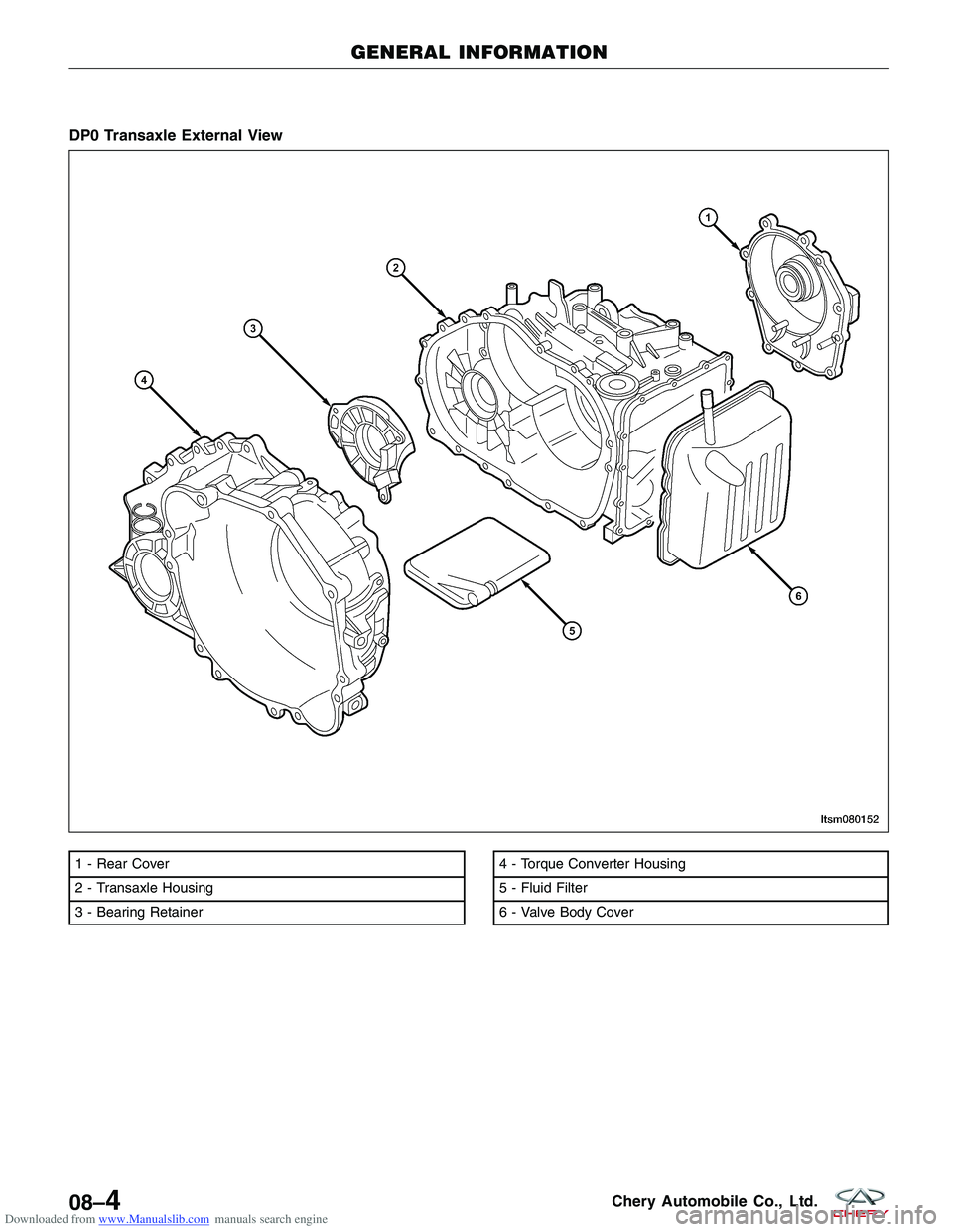
Downloaded from www.Manualslib.com manuals search engine DP0 Transaxle External View
1 - Rear Cover
2 - Transaxle Housing
3 - Bearing Retainer4 - Torque Converter Housing
5 - Fluid Filter
6 - Valve Body Cover
GENERAL INFORMATION
LTSM080152
08–4Chery Automobile Co., Ltd.
Page 948 of 1903
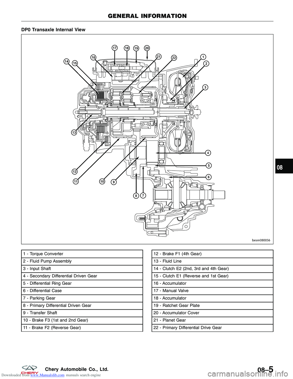
Downloaded from www.Manualslib.com manuals search engine DP0 Transaxle Internal View
1 - Torque Converter
2 - Fluid Pump Assembly
3 - Input Shaft
4 - Secondary Differential Driven Gear
5 - Differential Ring Gear
6 - Differential Case
7 - Parking Gear
8 - Primary Differential Driven Gear
9 - Transfer Shaft
10 - Brake F3 (1st and 2nd Gear)
11 - Brake F2 (Reverse Gear)12 - Brake F1 (4th Gear)
13 - Fluid Line
14 - Clutch E2 (2nd, 3rd and 4th Gear)
15 - Clutch E1 (Reverse and 1st Gear)
16 - Accumulator
17 - Manual Valve
18 - Accumulator
19 - Ratchet Gear Plate
20 - Accumulator Cover
21 - Planet Gear
22 - Primary Differential Drive Gear
GENERAL INFORMATION
BESM080056
08
08–5Chery Automobile Co., Ltd.
Page 949 of 1903
Downloaded from www.Manualslib.com manuals search engine Operation
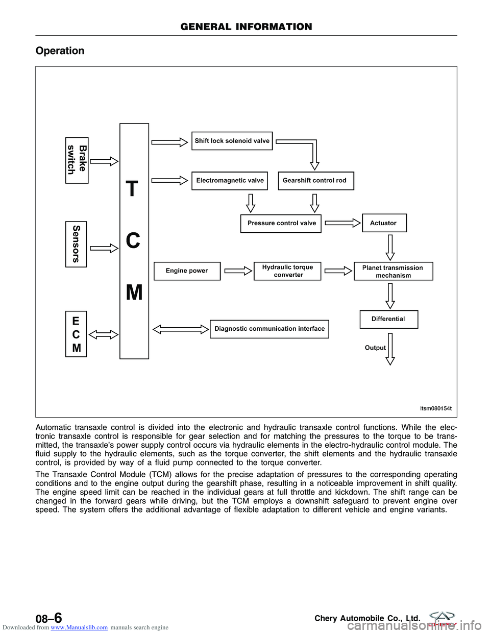
Automatic transaxle control is divided into the electronic and hydraulic transaxle control functions. While the elec-
tronic transaxle control is responsible for gear selection and for matching the pressures to the torque to be trans-
mitted, the transaxle’s power supply control occurs via hydraulic elements in the electro-hydraulic control module. The
fluid supply to the hydraulic elements, such as the torque converter, the shift elements and the hydraulic transaxle
control, is provided by way of a fluid pump connected to the torque converter.
The Transaxle Control Module (TCM) allows for the precise adaptation of pressures to the corresponding operating
conditions and to the engine output during the gearshift phase, resulting in a noticeable improvement in shift quality.
The engine speed limit can be reached in the individual gears at full throttle and kickdown. The shift range can be
changed in the forward gears while driving, but the TCM employs a downshift safeguard to prevent engine over
speed. The system offers the additional advantage of flexible adaptation to different vehicle and engine variants.
GENERAL INFORMATION
LTSM080154T
08–6Chery Automobile Co., Ltd.
Page 950 of 1903
Downloaded from www.Manualslib.com manuals search engine Specifications
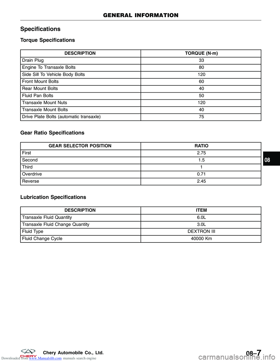
Torque Specifications
DESCRIPTIONTORQUE (N·m)
Drain Plug 33
Engine To Transaxle Bolts 80
Side Sill To Vehicle Body Bolts 120
Front Mount Bolts 60
Rear Mount Bolts 40
Fluid Pan Bolts 50
Transaxle Mount Nuts 120
Transaxle Mount Bolts 40
Drive Plate Bolts (automatic transaxle) 75
Gear Ratio Specifications
GEAR SELECTOR POSITIONRATIO
First 2.75
Second 1.5
Third 1
Overdrive 0.71
Reverse 2.45
Lubrication Specifications
DESCRIPTIONITEM
Transaxle Fluid Quantity 6.0L
Transaxle Fluid Change Quantity 3.0L
Fluid Type DEXTRON III
Fluid Change Cycle 40000 Km
GENERAL INFORMATION
08
08–7Chery Automobile Co., Ltd.