CHEVROLET BLAZER 1995 2.G Owners Manual
Manufacturer: CHEVROLET, Model Year: 1995, Model line: BLAZER, Model: CHEVROLET BLAZER 1995 2.GPages: 380, PDF Size: 20.04 MB
Page 131 of 380
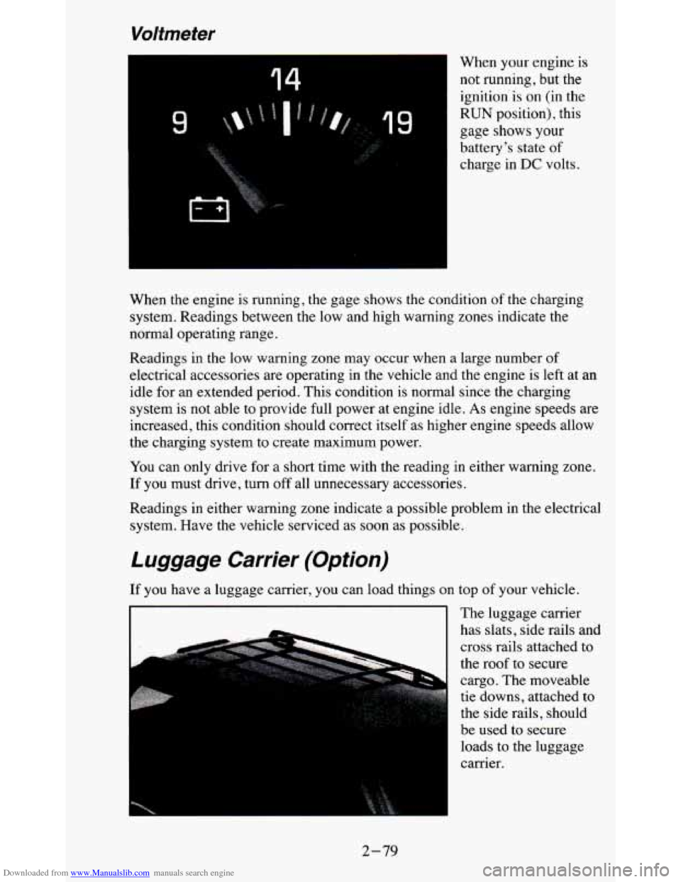
Downloaded from www.Manualslib.com manuals search engine Voltmeter
14
49
When your engine is
not running, but the ignition'is on (in the
RUN position), this
gage shows
your
battery's state of
charge in DC volts.
When the engine is running, the gage shows the condition of the charging
system. Readings between the low and high warning zones indicate the
normal operating range.
Readings in the low warning zone may occur when a large number of
electrical accessories are operating in the vehicle and the engine is left at an
idle for an extended period. This condition is normal since
the charging
system is not able to provide full power at engine idle.
As engine speeds are
increased, this condition should correct itself as higher engine speeds allow
the charging system to create maximum power.
You can only drive for
a short time with the reading in either warning zone.
If you must drive, turn
off all unnecessary accessories.
Readings in either warning zone indicate a possible problem in the electrical
system. Have the vehicle serviced as soon as possible.
Luggage Carrier (Option)
If you have a luggage carrier, you can load things on top of your vehicle.
The luggage carrier
has slats, side rails and
cross rails attached to
the roof to secure
cargo. The moveable
tie downs, attached to
the side rails, should
be used to secure loads to the luggage
carrier.
I I
2-79
Page 132 of 380
Downloaded from www.Manualslib.com manuals search engine Use GM accessory racks that are compatible with your luggage carrier for
transporting sports equipment. These are available through your
GM dealer.
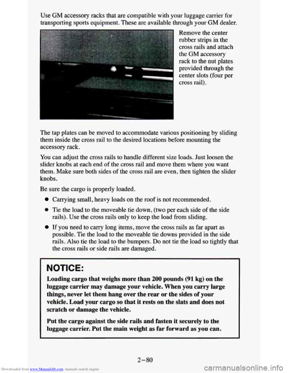
Remove the center
rubber strips
in the
cross rails and attach
the
GM accessory
rack to the nut plates
provided through the center slots (four per
cross rail).
The tap plates can be moved to accommodate various positioning by sliding
them inside the cross rail to the desired locations before mou\
nting the
accessory rack.
You can adjust the cross rails to handle different size loads. Just loosen the
slider knobs at each end of the cross rail and move them where you want
them. Make sure both sides of the cross rail are even, then tighten the slider
knobs.
Be sure the cargo is properly loaded.
Carrying small, heavy loads on the roof is not recommended.
0 Tie the load to the moveable tie down, (two per each side of the side
rails). Use the cross rails only to keep the load from sliding.
If you need to carry long items, move the cross rails as far apart as
possible. Tie the load to the moveable
tie downs provided in the side
rails. Also tie the load to the bumpers.
Do not tie the load so tightly that
the cross rails or side rails are damaged.
NOTICE:
Loading cargo that weighs more than 200 pounds (91 kg) on the
luggage carrier may damage your vehicle. When you carry large
things, never let them hang over the rear or the sides of your
vehicle. Load your cargo
so that it rests on the slats and does not
scratch
or damage the vehicle.
Put the cargo against the side rails and fasten it securely to the
luggage carrier. Put the main weight as far forward as you can.
2-80
Page 133 of 380
Downloaded from www.Manualslib.com manuals search engine Don’t exceed the maximum vehicle capacity when loading your vehicle. For
more information on vehicle capacity and loading,
see “Loading Your
Vehicle’’ in the Index.
To prevent damage or loss of cargo as you’re driving, check
now and then to
make sure the luggage carrier and cargo are still securely fastened.
Trailer Wiring Harness
Your vehicle will have a 5-wire and may have a 7-wire harness.
The light duty trailer wiring is a 5-wire harness assembly taped and bundled
at the left corner
of the vehicle. The harness has no connector, and you
should have
a qualified service person wire your harness for you.
The heavy duty trailer wiring is
a 7-wire harness assembly. It is stored
under the vehicle, along the passenger-side frame crossmember on
two-door vehicles and on the driver-side corner frame crossmember on
four-door vehicles. It has a 30-amp feed wire with an inline fuse located by
the junction block. See “Fuses and Circuit Breakers” in
the Index.
Both the 5-wire harness and the 7-wire harness have no connector and
should be wired by a qualified service person. Attach the harness to the
trailer, then tape or strap
it to your vehicle’s frame rail. Be sure you leave it
loose enough
so the wiring doesn’t bend or break, but not so loose that it
drags on the ground.
Store the harness
in its original place. Wrap the harness together and tie it
neatly
so it won’t be damaged.
2-81
Page 134 of 380

Downloaded from www.Manualslib.com manuals search engine Notes
2-82
Page 135 of 380
Downloaded from www.Manualslib.com manuals search engine Comfort Controls & Audio Systems
Section
U
In this section you'll find out how to operate the comfort control systems
and audio systems offered with your vehicle. Be sure to read about the
particular system supplied with your vehicle.
Comfort Controls
Heater/Air Conditioning Controls
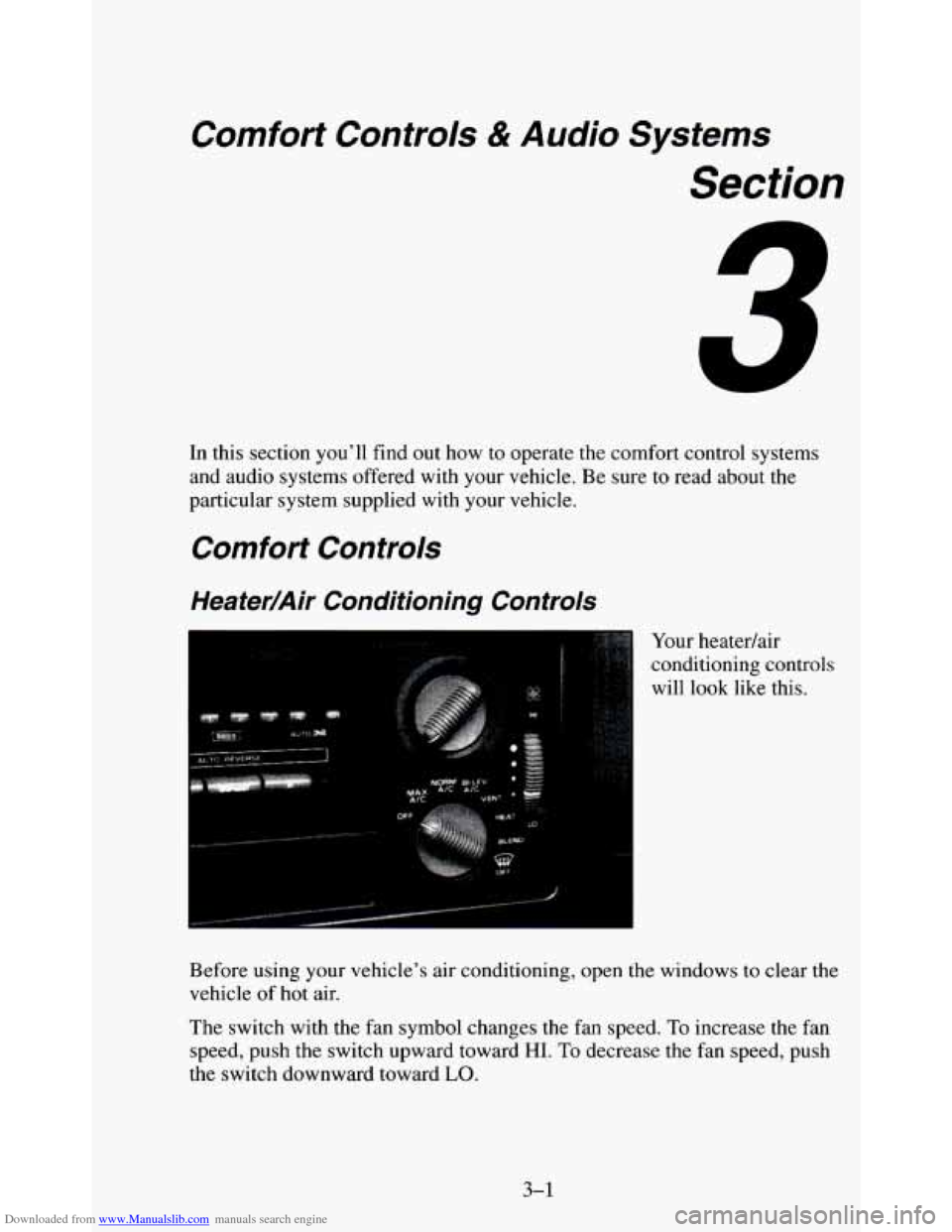
, ..,.. Your heatedair
conditioning controls
will look like this.
Before using your vehicle's air conditioning, open the windows to clear the
vehicle of
hot air.
The switch with the fan symbol changes the fan speed, To increase the fan
speed, push the switch upward toward HI. To decrease the fan speed, push
the switch downward toward
LO.
3-1
Page 136 of 380
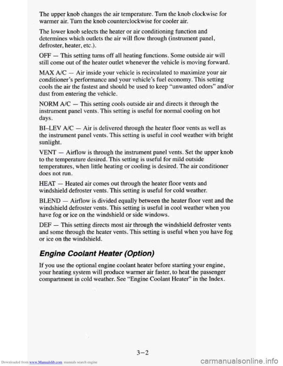
Downloaded from www.Manualslib.com manuals search engine The upper knob changes the air temperature. Turn the knob clockwise for
warmer air. Turn the knob counterclockwise for cooler air.
The lower knob selects the heater
or air conditioning function and
determines which outlets the air will flow through (instrument panel,
defroster, heater, etc
.).
OFF - This setting turns off all heating functions. Some outside air will
still come
out of the heater outlet whenever the vehicle is moving forward.
MAX A/C - Air inside your vehicle is recirculated to maximize your air
conditioner’s performance and your vehicle’s fuel economy. This setting
cools the air the fastest and should be used to keep “unwanted odors” and/or
dust from entering the vehicle.
NORM A/C - This setting cools outside air and directs it through the
instrument panel vents. This setting is useful for normal cooling on hot
days.
BI-LEV A/C
- Air is delivered through the heater floor vents as well as
the instrument panel vents. This setting is useful in cool weather with bright
sunlight.
VENT
- Airflow is through the instrument panel vents. Set the upper knob
to the temperature desired. This setting
is useful for mild outside
temperatures, when little heating or cooling is desired. The air conditioner
does not run.
HEAT
- Heated air comes out through the heater floor vents and
windshield defroster vents. This setting is useful for cold weather.
BLEND
- Airflow is divided equally between the heater floor vent and the
windshield defroster vents. This setting is useful in cool weather when you
have fog or ice on the windshield or side windows.
DEF - This setting directs most air through the windshield defroster vents
and some through the heater vents. This setting is useful when you have fog
or ice on the windshield.
Engine Coolant Heater (Option)
If you use the optional engine coolant heater before starting your engine,
your heating system will produce warmer air faster, to heat the passenger
compartment in cold weather. See “Engine Coolant Heater” in the Index.
3-2
Page 137 of 380
Downloaded from www.Manualslib.com manuals search engine Rear Window Defogger (Option)
If your vehicle has this option, the rear window will have lines running
across the glass. These lines heat your window.
For best results, clear the window of as much snow or ice as possible before
using the rear window defogger.
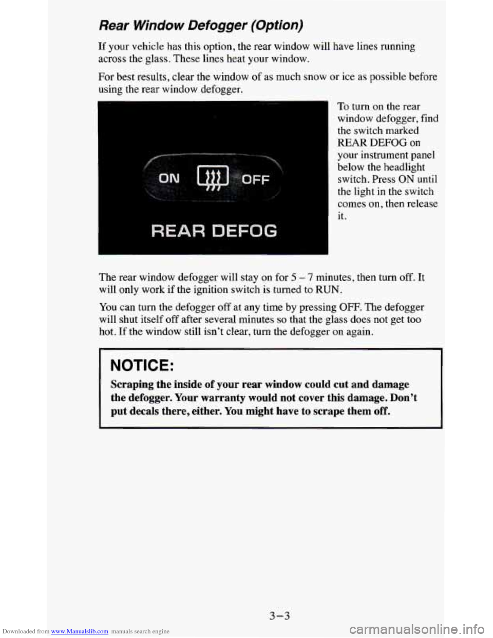
REAR DEFOG
-
To turn on the rear
window defogger, find
the switch marked
REAR
DEFOG on
your instrument panel
below the headlight switch. Press ON until
the light in the switch
comes on, then release
it.
The rear window defogger will stay on for
5 - 7 minutes, then turn off. It
will only work if the ignition switch is turned to RUN.
You can
turn the defogger off at any time by pressing OFF. The defogger
will shut itself off after several minutes
so that the glass does not get too
hot.
If the window still isn’t clear, turn the defogger on again.
NOTICE:
Scraping the inside of your rear window could cut and damage
the defogger. Your warranty would not cover this damage. Don’\
t
put decals there, either. You might have to scrape them
off.
3-3
Page 138 of 380
Downloaded from www.Manualslib.com manuals search engine Ventilation System
L
L
I‘ -a
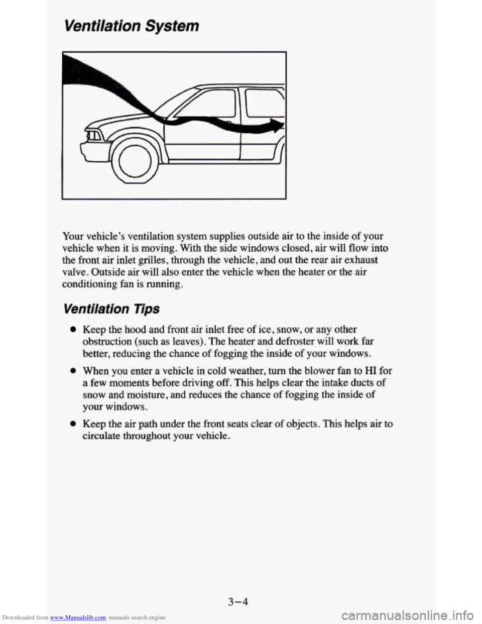
Your vehicle’s ventilation system supplies outside air to the insi\
de of your
vehicle when it is moving. With the side windows closed, air will flow into
the front air inlet grilles, through the vehicle, and out the rear air exhaust
valve. Outside air will also enter the vehicle when the heater or the
air
conditioning fan is running.
Ventilation Tips
Keep the hood and front air inlet free of ice, snow, or any other
obstruction (such as leaves). The heater and defroster will work far
better, reducing
the chance of fogging the inside of your windows.
0 When you enter a vehicle in cold weather, turn the blower fan to HI for
a
few moments before driving off. This helps clear the intake ducts of
snow and moisture, and reduces the chance of fogging the inside
of
your windows.
0 Keep the air path under the front seats clear of objects. This helps air to
circulate throughout your vehicle.
3-4
Page 139 of 380
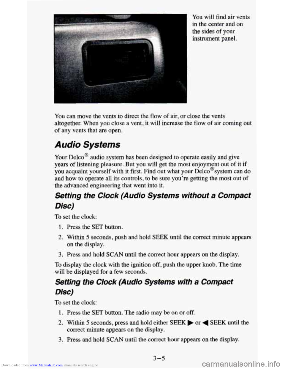
Downloaded from www.Manualslib.com manuals search engine You will find air vents
in the center and
on
the sides of your
instrument panel.
You can move the vents to direct the
flow of air, or close the vents
altogether. When you close a vent, it will increase the flow of air coming out
of any vents that are open.
Audio Systems
Your Delco@ audio system has been designed to operate easily and give
years of listening pleasure. But you will get the most enjoyment out of it if
you acquaint yourself with it first. Find out what your Delco@system can do
and how to operate all its controls, to be sure you're getting the most out of
the advanced engineering that went into it.
Setting the Clock (Audio Systems without a Compact
Disc)
To set the clock:
1. Press the SET button.
2. Within 5 seconds, push and hold SEEK until the correct minute appears
3. Press and hold SCAN until the correct hour appears on the display.
on the display.
To display the clock with the ignition off, push the upper knob. The time
will be displayed for a few seconds.
Setting the Clock (Audio Systems with a Compact
Disc)
To set the clock:
1. Press the SET button. The radio may be on or off.
2. Within 5 seconds, press and hold either SEEK or 4 SEEK until the
correct minute appears
on the display.
3. Press and hold SCAN until the correct hour appears on the display.
3-5
Page 140 of 380
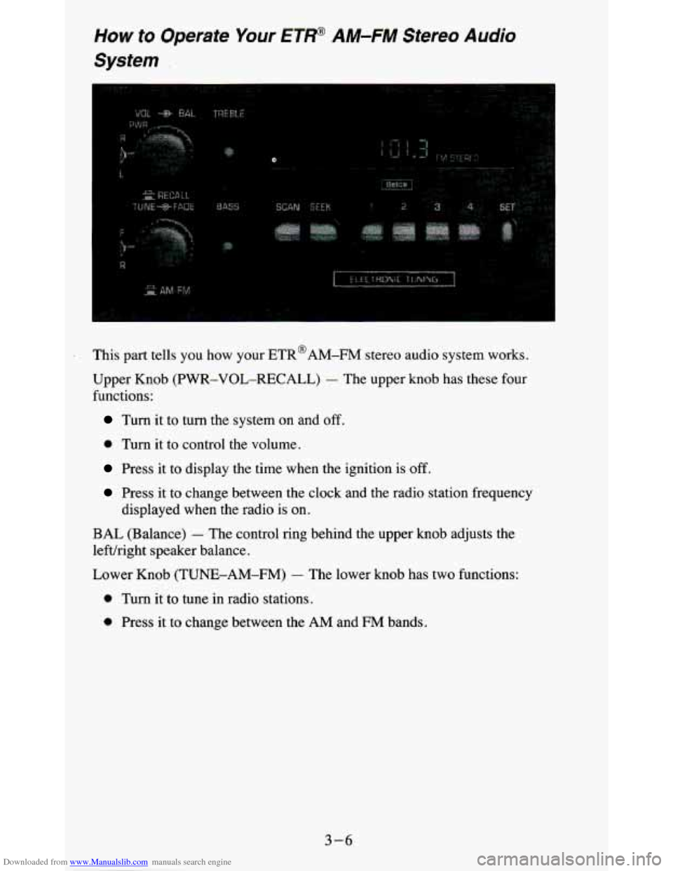
Downloaded from www.Manualslib.com manuals search engine How to Operate Your ETP AM-FM Stereo Audio
System
I
.. ..
Q
This part tells you how your ETR@AM-FM stereo audio system works.
Upper Knob (PWR-VOL-RECALL)
- The upper knob has these four
functions:
Turn it to turn the system on and off.
0 Turn it to control the volume.
Press it to display the time when the ignition is off.
Press it to change between the clock and the radio station frequency
displayed when the radio is on.
BAL (Balance) - The control ring behind the upper knob adjusts the
lefuright speaker balance.
Lower Knob (TUNE-AM-FM)
- The lower knob has two functions:
0 Turn it to tune in radio stations.
0 Press it to change between the AM and €34 bands.
3-6