steering CHEVROLET CAMARO 1967 1.G Chassis Owners Manual
[x] Cancel search | Manufacturer: CHEVROLET, Model Year: 1967, Model line: CAMARO, Model: CHEVROLET CAMARO 1967 1.GPages: 659, PDF Size: 114.24 MB
Page 538 of 659
ELECTRICAL-BODY
AND
CHASSIS
12-26
•
Low oil
pressure
• High engine temperature
• Defective wiring
or
switch
connector from sender
in block above starter
on
and
at
left front
of
distributor
on V-8
Sending Unit Replacement
1.
Disconnect wiring harness
unit terminal (located
L-6 engines
engines).
2.
Remove sender unit using Tool J-21757
or 12
point
socket, replace with
new
unit
and
check operation.
GENERATOR INDICATOR
1.
Ignition
on,
Engine
not
Running
and
Telltale Light
Off.
• Indicator bulb burned out, replace bulb.
• Open circuit
or
loose connection
in the
telltale
light circuit.
2.
telltale Light Stays
on
after Engine
is
Started.
If indicator light does
not go out at
engine idle
speed, refer
to
Charging Systems under Engine
Electrical, Section
6Y.
TEMPERATURE (COOLING SYSTEM) INDICATOR
The temperature indicator circuit consists
of two re-
motely located units, indicator gauge
and
engine sender
unit.
The
indicator gauge, located
in the
instrument
panel, consists
of a
red light which will indicate
an
over-
heated engine condition.
Engine Sender Unit Replacement
1.
Drain engine cooling system
to a
level below unit.
2.
Remove sender unit (located
in the
inlet manifold
near water pump housing
on V-8
engines and
in the
cylinder head near
an
exhaust port
oh L-6
engines)
and replace with new unit.
3.
Refill cooling system
and
check operation
of
unit.
CHEVELLE INSTRUMENTS AND GAUGES
INDEX
Page
General Description
* *
i2-26
Service Operations
12-26
Instrument Panel
12-26
Instrument Cluster.
12-26
Fuel Gauge and/or Ammeter
12-27
Clock,
i 12-27
Speedometer
12-27
Page
Speedometer Cable
.
. 12-27
Temperature Gauge
12-29
Oil Pressure Gauge
12-29
Indicator Lights.
. 12-29
Oil Pressure Indicator
12-29
Generator Indicator
. . 12-29
• Temperature Indicator
12-29
GENERAL DESCRIPTION
The Chevelle instrument cluster assembly consists
of:
a speedometer;
a
fuel gauge;
a
generator,
an
engine
tem-
perature and an
oil
pressure indicator lamp, and includes
a clock
on
deluxe models.
On
super sport models,
am-
meter, coolant temperature
and oil
pressure gauges
re-
place
the
appropriate indicator lights. Except
for the
speedometer,
all of the
indicator lamps, instruments
and
gauges
of
these clusters may
be
serviced without remov-
ing
the
instrument cluster assembly from
the
vehicle.
In addition
to the
instrument indicator lamps,
a
brake
warning lamp
is
included
in the
cluster
as
standard
equipment.
The
indicator
is
connected
to the
parking
brake
and
brake pressure differential switches
and
serves
a
dual function.
It
lights when the parking brake
is applied
and
also when
the
brake pedal
is
applied,
if a
malfunction should occur
in the
brake system
due to a
loss
of
hydraulic pressure. Servicing
of the
hydraulic
pressure differential switch
is
covered
in
Section
5 of
this manual.
Regular maintenance
is not
required on the instrument
cjLuster
or its
components other than maintaining dean
and tight electrical connections, replacing defective parts
and keeping
the
speedometer cable properly lubricated.
SERVICE OPERATIONS
INSTRUMENT PANEL ASSEMBLY
INSTRUMENT CLUSTER (Figs.
41
thru
44)
Removal
1.
Disconnect battery ground cable.
2.
Remove steering coupling bolt and disconnect steer-
ing shaft from coupling.
3.
Loosen mast jacket lower clamp.
4.
Remove
air
conditioning center distributor duct
(if
so equipped).
5. Remove radio rear support bracket screw.
6. Remove mast jacket upper support clamp and retain-
ing bolts from lower support (refer
to
Section
9,
Steering).
CAUTION: Cover mast jacket
and
parl
brake handle with
a
suitable material
to
prevc
scratching.
7.
Disconnect speedometer cable
at
rear
of
cluster
housing
and
speed warning control knob
at
panel
(if
so equipped).
8. Remove instrument panel retaining screws (nine
upper and five lower).
.
9. Working under the console remove four lower retain-
ing screws from instrument cluster housing.
10.
Pull instrument panel assembly from console and
lay
forward on mast jacket.
11.
Disconnect wiring harness, cluster lamps and wiring
CHEVROLET CHASSIS SERVICE MANUAL
Page 539 of 659
ELECTRICAL-BODY AND CHASSIS 12-27
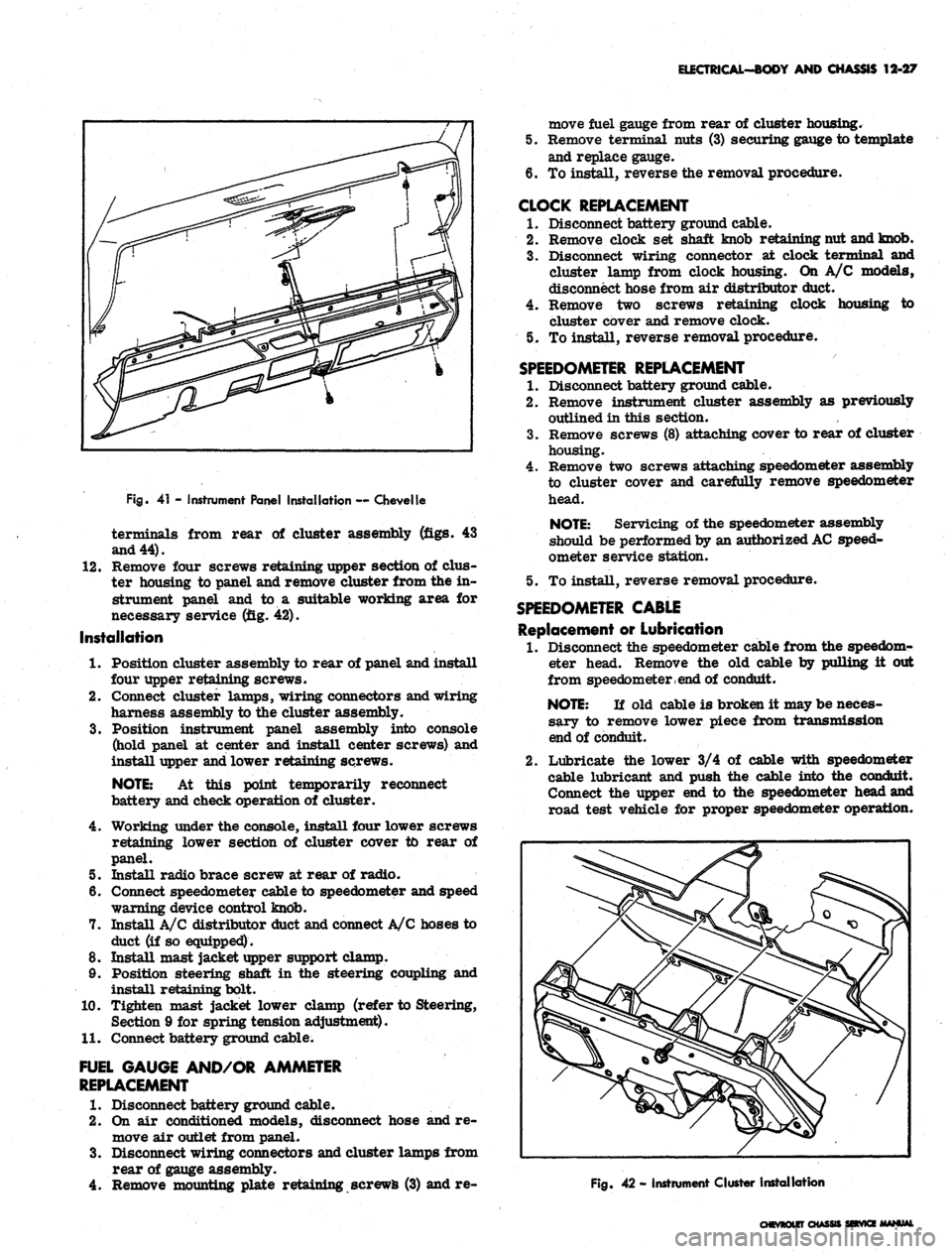
Fig.
41 - Instrument Panel Installation — Chevelle
terminals from rear of cluster assembly (figs. 43
and 44).
12.
Remove four screws retaining upper section of dus-
ter housing to panel and remove cluster from the in-
strument panel and to a suitable working area for
necessary service (fig. 42).
Installation
1.
Position cluster assembly to rear of panel and install
four upper retaining screws.
2.
Connect cluster lamps, wiring connectors and wiring
harness assembly to the cluster assembly.
3.
Position instrument panel assembly into console
(hold panel at center and install center screws) and
install upper and lower retaining screws.
NOTE:
At this point temporarily reconnect
battery and check operation of cluster.
4.
Working under the console, install four lower screws
retaining lower section of cluster cover to rear of
panel.
5. Install radio brace screw at rear of radio.
6. Connect speedometer cable to speedometer and speed
warning device control knob.
7. Install A/C distributor duct and connect A/C hoses to
duct (if so equipped).
8. Install mast jacket upper support clamp.
9. Position steering shaft in the steering coupling and
install retaining bolt.
10.
Tighten mast jacket lower clamp (refer to Steering,
Section 9 for spring tension adjustment).
11.
Connect battery ground cable.
FUEL GAUGE AND/OR AMMETER
REPLACEMENT
1.
Disconnect battery ground cable.
2.
On air conditioned models, disconnect hose and re-
move air outlet from panel.
3.
Disconnect wiring connectors and cluster lamps from
rear of gauge assembly.
4.
Remove mounting plate retaining screws (3) and re-
move fuel gauge from rear of cluster housing.
5. Remove terminal nuts (3) securing gauge to template
and replace gauge.
6. To install, reverse the removal procedure.
CLOCK REPLACEMENT
1.
Disconnect battery ground cable.
2.
Remove clock set shaft knob retaining nut and knob.
3.
Disconnect wiring connector at clock terminal and
cluster lamp from clock housing. On A/C models,
disconnect hose from air distributor duct.
4.
Remove two screws retaining clock housing to
cluster cover and remove clock.
5. To install, reverse removal procedure.
SPEEDOMETER REPLACEMENT
1.
Disconnect battery ground cable.
2.
Remove instrument cluster assembly as previously
outlined in this section.
3.
Remove screws (8) attaching cover to rear of cluster
housing.
4.
Remove two screws attaching speedometer assembly
to cluster cover and carefully remove speedometer
head.
NOTE:
Servicing of the speedometer assembly
should be performed by an authorized
AC
speed-
ometer service station.
5. To install, reverse removal procedure.
SPEEDOMETER CABLE
Replacement or Lubrication
1.
Disconnect the speedometer cable from the speedom-
eter head. Remove the old cable by pulling it out
from speedometer
, end
of conduit.
NOTE:
If old cable is broken it may be neces-
sary to remove lower piece from transmission
end of conduit.
2.
Lubricate the lower 3/4 of cable with speedometer
cable lubricant and push the cable into the conduit.
Connect the upper end to the speedometer head and
road test vehicle for proper speedometer operation.
Fig.
42 - Instrument Cluster Installation
CHEVROLET CHASSIS SEtVKE MANUAL
Page 543 of 659
ELECTRICAL-BODY
AND
CHASSIS
12-31
CHEVY II INSTRUMENTS AND GAUGES
INDEX
Page
Page
General Description -.....
12-31
Service Operations.
12-31
Instrument Panel
. 12-31
Instrument Cluster
12-31
Fuel Gauge
12-32
12-32
Clock,
Speedometer
12-34
Speedometer Catte
12-34
Indicator Lights
12-34
Oil Pressure Indicator
12-34
Generator Indicator
12-34
Temperature Indicator
12-34
GENERAL DESCRIPTION
The Chevy
n
instrument cluster assembly consists
of:
a speedometer;
a
fuel gauge;
a
generator, temperature
and
oil
pressure indicator lamps, and includes
a
clock
on
deluxe models. Except
for the
speedometer,
all of the
cluster lamps, instruments and gauges
of
the cluster
may
be serviced without removing
the
instrument cluster
as-
sembly from
the
console.
In addition
to the
instrument indicator lamps,
a
brake
warning lamp
is
included
in the
cluster
as
standard
equipment.
The
indicator
is
connected
to
thfc parking
brake and brake pressure differential switches andserves
a dual function.
It
lights when
the
parking brake
is ap-
plied
and
also when
the
brake pedal
is
applied,
if a mal-
function should occur
in the
brake system
due to a
loss
of
hydraulic pressure. Servicing
of the
hydraulic pressure
differential switch
is
covered
in
Section
5 of
this manaul.
Regular maintenance
is not
required on
the
instrument
cluster
or its
components other than r^Mfitftl^i^g clean
and tight electrical connections, replacing defective parts
and keeping
the
speedometer cable properly lubricated.
SERVICE OPERATIONS
INSTRUMENT PANEL
INSTRUMENT CLUSTER
Removal
and
Installation {Figs.
45
thru
48)
1.
Disconnect battery ground cable.
2.
Remove mast jacket upper support clamp (refer
to
Steering, Section
9, for
complete procedure
on low-
ering jacket) and lower steering column.
NOTE:
Apply protective material
to the
mast
jacket
to
prevent damage
to the
painted surfaces.
3.
Disconnect retaining collar securing speedometer
cable
to
speedometer head.
4.
Remove screws retaining cluster
to
console.
5. Pull cluster forward
of
console opening and discon-
nect
all
wiring
and
lamp connections. Remove
cluster from vehicle.
CAUTION:
Do not
pull cluster outward further
than slack
in
wiring harness will allow, other-
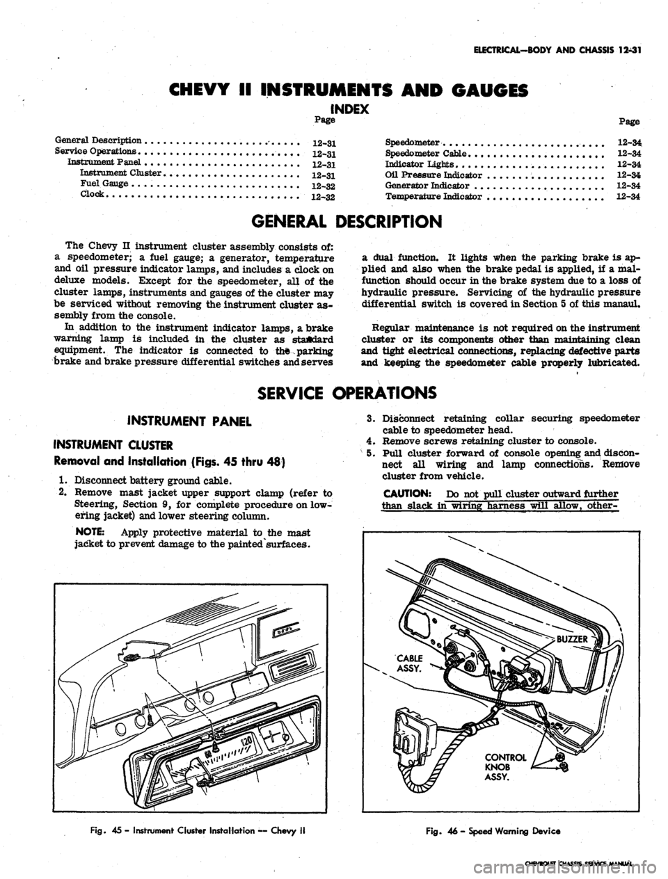
Fig.
45-
Instrument Cluster Installation
—
Chevy
II
Fig.
46 -
Speed Warning Device
CHEVtOtET CHASSIS SERVICE MANUAL
Page 548 of 659
ELECTRICAL-BODY
AND
CHASSIS
12-36
CAMARO INSTRUMENTS AND GAUGES
INDEX
Page
General Description
12-36
Service Operations
12-36
Instrument Cluster
. . . 12-36
Instrument Lamps
12-36
Printed Circuit
12-36
Fuel Gauge
12-37
Tachometer
. . 12-37
Seat Separator Instrument Console
12-37
Page
Fuel Gauge
12-37
Ammeter
12-37
Temperature Gauge
12-37
Oil Pressure Gauge
. 12-37
Fuel Warning Unit
12-37
Clock.
... 12-37
Oil Pressure Indicator
12-37
Generator Indicator
12-38
Temperature Indicator
12-38
GENERAL DESCRIPTION
The standard Camaro instrument cluster assembly con-
sists
of two
circular units which house
the
speedometer
and fuel gauge assemblies.
The oil
pressure, left-hand
directional
and
brake warning indicators
are
located
in
the face
of the
speedometer bezel while generator,
tem-
perature
and
right-hand directional indicators are grouped
with
the
fuel gauge unit.
The
high beam indicator
is
located between
the
cluster bezels.
A special instrumentation package
is
available with
the
eight-cylinder engine
and
center floor console combina-
tion.
The
special cluster includes:
a
clock; coolant
temperature,
oil
pressure, fuel
and
ammeter gauges,
mounted forward
on the
seat separator console;
a ta-
chometer
in the
right circular housing
of the
dash
in-
strument cluster; and
a low
fuel level indicator replacing
the
oil
pressure indicator lamp
in the
instrument cluster.
The instruments
and
gauges,
may be
serviced only
after
the
instrument cluster
is
removed from
the
vehicle.
Indicator
and
cluster lamps except
for the
high beam
indicator
may be
replaced without removing
the
cluster
assembly. Partial cluster removal
is
necessary when
replacing
the
high beam indicator due
to its
proximity
to
the upper brace
rod
anchor plate.
The
bulbs
are in-
stalled
in
plastic sockets which lock into
the
cluster
housing and make contact with
the
printed circuit.
A
low
level fuel warning system
is a
special feature
available with
the
floor console gauge pack. This
sys-
tem includes
an
indicator lamp
in the
dash cluster and
a
semi-conductor unit senses
the
change
in
electrical
re-
sistance
of the
fuel system circuitry
as
variations
in
fuel level occur.
The
sensing device
is
replaced
as a
unit
if
found defective.
The brake warning light serves
a
dual purpose.
It
functions
as an
indicator when
the
parking brake
is ap-
plied
and
also
if
there
is a
malfunction (loss
of
hydraulic
pressure)
in the
brake system. Switches which provide
the signal
to
operate
the
light
are
located
at the
parking
brake assembly
and at the
brake master cylinder
in the
hydraulic lines. Service
of the
brake pressure differ-
ential switch unit
is
covered
in
Section
5 of
this manual.
Regular maintenance
is not
required on
the
instrument
cluster
or its
components other than maintaining clean,
tight electrical connections, replacing defective parts
and keeping
the
speedometer properly lubricated.
SERVICE OPERATIONS
INSTRUMENT CLUSTER (Figs.
50
thru
53)
Removal
and
Installation
1.
Disconnect battery ground cable.
2.
Remove mast jacket lower support screws
at toe
pan.
3.
Remove mast jacket upper support bolts
and
allow
steering wheel
to
rest
on
seat cushion.
CAUTION: Both supports must
be
detached
to
prevent distortion
of
mast jacket.
4.
Remove cluster attaching screws from face
of
panel
and partially remove assembly from console opening.
5. Reaching behind cluster assembly, disconnect speed-
ometer cable, speed warning device
(if so
equipped
-
Fig.
51) and
chassis harness connector
at
rear
of
panel.
6. Remove assembly from console opening to
a
suitable
bench area
for
required service operations.
7.
To
install, reverse removal procedure.
INSTRUMENT CLUSTER LAMP REPLACEMENT
1.
Turn bulb holder counterclockwise
and
pull
out to
remove from
the
cluster housing.
2.
Pull bulb straight out
to
remove from socket.
3.
Press replacement bulb inward
to
lock
in
socket.
4.
Insert lamp assembly into housing, with lugs
on
holder entering notches
in
housing,
and
turn clock-
wise
to
lock
in
place.
PRINTED CIRCUIT REPLACEMENT
1.
Remove instrument cluster
as
previously described
in this section.
2.
Remove
all
cluster illuminating and indicator lamps
from housing.
3.
Remove fuel gauge terminal nuts
or
tachometer
re-
taining nuts securing printed circuit
to
housing.
4.
Remove four
hex
head screws retaining printed
cir-
cuit
to the
cluster housing
and
remove circuit from
housing.
5.
To
install, reverse removal procedure.
CAUTION:
The
retaining screws
are
part
of
the grounding circuit
and
must
be
installed
to
provide proper connections
for the
printed
eir-
cuit.
CHEVROLET CHASSIS SERVICE MANUAL
Page 552 of 659
ELECTRICAL-BODY AND CHASSIS 12-40
Fig.
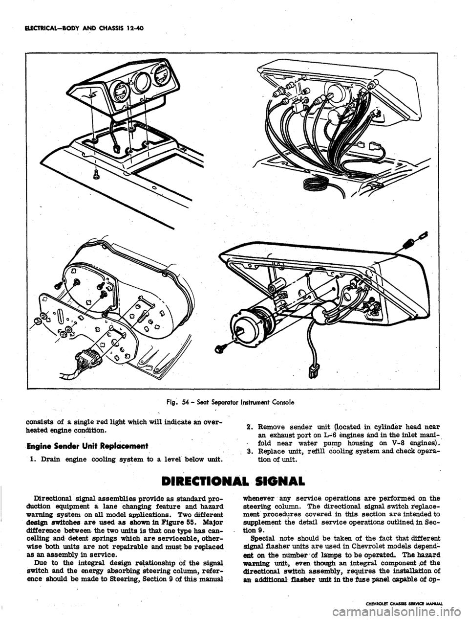
54 - Seat Separator Instrument Console
consists of a single red light which will indicate an over-
heated engine condition.
Engine Sender Unit Replacement
1.
Drain engine cooling system to a level below unit.
2.
Remove sender unit (located in cylinder head near
an exhaust port on L-6 engines and in the inlet mani-
fold near water pump housing on V-8 engines).
3.
Replace unit, refill cooling system and check opera-
tion of unit.
DIRECTIONAL SIGNAL
Directional signal assemblies provide as standard pro-
duction equipment a lane changing feature and hazard
warning system on all model applications. Two different
design switches are used as shown in Figure 55. Major
difference between the two units is that one type has can-
celling and detent springs which are serviceable, other-
wise both units are not repairable and must be replaced
as an assembly in service.
Due to the integral design relationship of the signal
switch and the energy absorbing steering column, refer-
ence should be made to Steering, Section 9 of this manual
whenever any service operations are performed on the
steering column. The directional signal switch replace-
ment procedures covered in this section are intended to
supplement the detail service operations outlined in Sec-
tion 9.
Special note should be taken of the fact that different
signal flasher units are used in Chevrolet models depend-
ent on the number of lamps to be operated. The hazard
warning unit, even though an integral component of the
directional switch assembly, requires the installation of
an additional flasher unit in the fuse panel capable of op-
CHEVROtET CHASSIS SERVICE MANUAL
Page 553 of 659

ELECTRICAL-BODY AND CHASSIS 12-41
HAZARD WARNING
SWITCHES
Fig.
55- Directional Signal Switches
erating six to eight lamps simultaneously depending ve-
hicle series and model.
DIRECTIONAL SIGNAL SWITCH REPLACEMENT
All steering columns except tilt and telescoping.
Chevrolet, Chevelle, Chevy II and Camaro (Fig. 56)
1.
Disconnect battery ground cable.
2.
Disconnect signal switch wiring from chassis har-
ness at multiple connector under instrument panel.
3.
Remove steering wheel assembly as outlined in Sec-
tion 9, Steering.
4.
Remove shift lever roll pin and shift lever from
column (if applicable).
5. Push in hazard warning switch knob and unscrew
knob.
Remove switch lever arm.
6. On Chevy U and Camaro models equipped with auto-
matic transmission remove column mounted dial in-
dicator housing and lamp assembly (if applicable).
7. Remove mast jacket lower trim cover retaining
screws and remove trim cover(s).
8. On Chevrolet and Chevelle models equipped with
automatic transmission loosen set screw and remove
quadrant dial pointer (if applicable).
9. Remove retaining
"C"
ring from upper steering shaft
using snap ring remover Tool J-22569 (Refer to
Steering, Section 9). Slide thrust and wave washers
from steering shaft.
10.
Loosen three signal switch mounting screws until
assembly can be rotated counterclockwise.
NOTE:
Do not remove three screws from as-
sembly until unit is on the bench.
11.
Rotate switch assembly counterclockwise and pull
unit from top of mast jacket. Allow unit to hang
from end of column.
Fig.
56 - Standard Steering Column
CHEVROLET CHASSIS SERVICE
Page 554 of 659
ELECTRICAL-BODY AND CHASSIS 12-42
Fig.
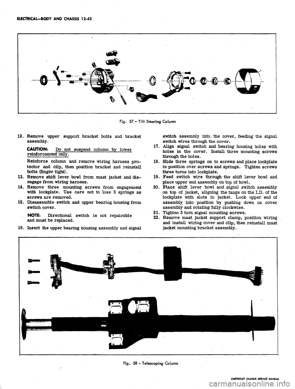
57 - Tilt Steering Column
12.
Remove upper support bracket bolts and bracket
assembly.
CAUTION: Do not suspend column by lower
reinforcement only.
Reinforce column and remove wiring harness pro-
tector and clip, then position bracket and reinstall
bolts (finger tight).
13.
Remove shift lever bowl from mast jacket and dis-
engage from wiring harness.
14.
Remove three mounting screws from engagement
with lockplate. Use care not to lose 3 springs as
screws are removed.
15.
Disassemble switch and upper bearing housing from
switch cover.
NOTE:
Directional switch is not repairable
and must be replaced.
16.
Insert the upper bearing housing assembly and signal
switch assembly into, the cover, feeding the signal
switch wires through the. cover.
17.
Align signal switch and bearing housing holes with
holes in the cover. Install three mounting screws
through the holes.
18.
Slide three springs on to screws and place lockplate
in position over screws and springs. Tighten screws
three turns into lockplate.
19.
Feed switch wire through the shift lever bowl and
place upper end assembly on top of bowl.
20.
Place shift lever bowl and signal switch assembly
on top of jacket, aligning the tangs on the I.D. of the
lockplate with slots in jacket. Lock upper end of
assembly into position by pushing down on cover
assembly and rotating fully clockwise.
21.
Tighten 3 turn signal mounting screws.
22.
Remove mast jacket support clamp, position wiring
and install wiring cover and clip, then reinstall mast
jacket mounting bracket assembly.
Fig.
58 - Telescoping Column
CHEVROLET CHASSIS SERVICE MANUAL
Page 555 of 659
ELECTRICAL-BODY AND CHASSIS 12-43
23.
Install
MCtT
ring over steering shaft using snap ring
installer J-22659 (refer to Section 9).
NOTE: Be sure retaining ring is completely
seated into groove.
24.
Install dial pointer on Chevrolet and Chevelle models
equipped with automatic transmission (if applicable).
25.
Install dial indicator and lamp assembly on Camaro
and Chevy n models equipped with automatic
transmission.
26.
Install mast jacket lower trim covers (if applicable).
27.
Install hazard warning knob and turn signal lever.
28.
Install shift lever.
29.
Install steering wheel.
30.
Install multiple connector to switch wiring using old
harness for wire color guide and connect to body
harness connector.
31.
Connect battery ground cable and check operation of
assembly.
Tilt Steering Column (Fig. 57)
Chevrolet, Chevelle and Camaro
1.
Disconnect battery ground cable.
2.
Disconnect directional switch wiring harness from
body harness at multiple connector under instrument
panel.
3.
Remove steering wheel assembly (refer to Steering,
Section 9).
4.
Remove preload spring and cancelling cam from end
of shaft.
5.
Remove shift lever pin and lever from steering col-
umn (except floor shift).
6. Remove directional le*ver screw and lever.
7.
Push in hazard warning knob and unscrew knob.
8. On Camaro models equipped with automatic trans-
mission, remove quadrant dial and lamp assembly
from column.
9. Remove mast jacket trim cover
(s).
10.
On Chevrolet and Chevelle models with automatic
transmission, loosen set screw and remove quadrant
dial pointer.
11.
Assemble slide hammer Tool J-6585-1 to turn signal
cover remover Tool J-21486. Place cover remover
over turn signal cover, tighten clamp, and pull cover
from end of column with slide hammer (Refer to
Steering, Section 9).
12.
Remove three switch mounting screws, noting short
length of top screw.
13.
Cut multiple connector from switch wiring and slide
switch from end of column.
14.
To install new switch, feed wiring through the bear-
ing housing, around support, and through shift bowl
and shroud.
15.
Feed through wiring protector. If clearance is not
sufficient loosen mast jacket bracket retaining bolts.
16.
Insert switch wiring terminals in multiple connector.
Use old connector
and
wiring for color guide.
17.
Position switch and install three mounting screws
with short screw in top position.
18.
Be sure hazard warning switch is pushed in, then
install turn signal cover using special Tool J-21853.
On automatic columns align key in cover with keyway
in bearing housing.
19.
Install turn signal lever, hazard warning knob and
tilt lever.
20.
Install shift lever and roll pin (where applicable).
21.
Install dial pointer on Chevrolet and Chevelle. On
Camaro install dial indicator and lamp assembly.
22.
Install trim covers and retaining screws.
23.
Install cancelling cam and preload spring.
24.
Install steering wheel (Refer to Section 9).
25.
Connect switch wiring to body harness under instru-
ment panel.
26.
Connect battery ground cable and check operation of
unit.
Standard and Telescoping Steering Column
Corvette (Fig. 58)
1.
Disconnect battery ground cable.
2.
Disconnect signal switch harness wiring from chas-
sis wiring harness at multiple connector under in-
strument panel.
3.
Remove steering wheel assembly as outlined in
Steering, Section 9.
4.
Remove preload spring and cancelling cam.
5.
Remove directional signal lever screw and lever.
6. Push in hazard warning knob, unscrew and remove
knob.
7.
Remove lower trim cover retaining screws and
cover.
8. Remove retaining ring, thrust and wave washers
from upper end of shaft.
9. Cut wiring above connector.
10.
Remove three switch mounting screws, slide switch,
cover and upper bearing housing from column, pull-
ing wire through protector and escutcheon.
11.
To install replacement switch, assemble upper bear-
ing housing and turn signal switch into switch cover,
then feed wiring through escutcheon and protector
until switch can be positioned on mast jacket.
12.
With switch positioned on mast jacket, install three
switch mounting screws.
13.
Install thrust and wave washers and snap lock ring
in place.
14.
Install turn signal lever and hazard warning knob.
15.
Install cancelling cam and upper bearing preload
spring on steering shaft.
16.
Install steering wheel assembly.
NOTE:
Be sure directional signal switch is in
neutral position before installing wheel.
17.
Install connector on directional signal wiring har-
ness and connect to body harness connector.
CHEVROLET CHASSIS SERVICE
Page 628 of 659
SPECIFICATIONS
HEATING
AND AIR
CONDITIONING
SECTION
1A
Compressor
Make Frigidaire
Type
. 6
Cylinder Axial
Displacement
Four-Season
12.6
Cu.
In.
Universal
and
Ail-Weather
.... .10.8 Cu. In.
Rotation Clockwise
Compressor Suction
and
Discharge
Connector Bolt Torque
.......
25 ft lbs.
Compressor Clutch Coil
Ohms
(at
80°F.).
4.18-4.38
Amps
(at
80°F.)
2.86 @ 12
Volts
Torques
Rear Head
to
SheU Stud
Nut 23 lb. ft
Shaft Mounting
Nut 15 lb. ft
Belt Tension.
See
Tune-Up Chart
System Capacities
Refrigerant
R-12
Four-Season
and
Comfortron
Systems.
............
3 lbs., 12 oz.
Universal Systems
Chevrolet, Chevelle,
and
Camaro.
... 3 lbs.
Chevy
n 2 lbs. 8 oz.
All-Weather System
2 lbs. 8 oz.
Compressor
Oil 525
Viscosity
All Systems
11 oz.
Fuses
Comfortron Systems
.
Four-Season Systems
.
Universal Systems
. .
All-Weather System.
.
Fuse
Block
25
amp.
25
amp.
25
amp.
25
amp.
In
Line
30
amp.
30
amp.
20
amp.
20
amp.
SECTION
3
WHEEL ALIGNMENT SPECIFICATIONS (Vehicle
dt
Curb Weight)
Caster*
Camber*
Steering Axis
Inclination
tToe-In (Total)
Wheel Bearing
Adjustment
Preload
End Movement
Chevrolet
Pos.
3/4° ± 1/2°
Pos.
1/4° ± 1/2°
7-1/2° ± 1/2°
@l/8"
to 1/4"
12 ft lbs.
zero
.001"
to .008"
Chevelle •
(SS and El Camino)
Neg. 1/2° ± 1/2°
(All others)
Neg. 1° ± 1/2°
Pos.
1/2° ± 1/2°
8-1/4° ± 1/2°
1/8" to 1/4"
12 ft lbs.
zero
.001"
to .008"
Chevy n
Pos.
1° ± 1/2°
Pos.
1/2° ± 1/2°
7° ± 1/2°
1/4" to 3/8"
12 ft lbs.
zero
.000"
to .004"
Corvette
Pos.
1° ± 1/2°
Pos.
3/4° ± 1/2°
7° ± 1/2°
3/16" to 5/16"
12 ft lbs.
zero
.001"
to .008"
Camaro
Pos.
1/2° £ 1/2°
Pos.
1/4° ±1/2°
8 3/4° ± 1/2°
1/8" to 1/4"
12 ft lbs.
zero
.001"
to .008"
•Must not vary more than 1/2° from side to side.
@Toe-In (Total) should be 5/16" to 7/16" after rebuild using new bushings and ball joints.
tAdjust Toe-in with steering gear on straight ahead location after camber and caster have been set Any change
in caster and camber settings will affect toe; always recheck and set toe to specifications.
LET CHASSIS SERVICE MANUAL
Page 629 of 659
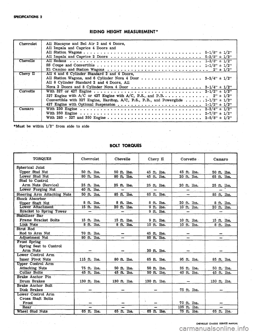
SPECIFICATIONS
2
RIDING HEIGHT MEASUREMENT*
Chevrolet
All Biscayne
and Bel Air 2 and 4
Doors,
All Impala
and
Caprice
4
Doors
and
All Station Wagons
. . . .
All Impala
and
Caprice
2
Doors
. . . . .
5-1/8"
± 1/2"
5-3/8"
± 1/2"
Chevelle
All Sedans
SS Coupe
and
Convertible
El Camino
and
Station W*
1-3/811
± 1/2"
1-1/8"
± 1/2"
..
2" ± 1/2"
Chevy
u
All
4 and 6
Cylinder Standard
2 and 4
Doors,
All Station Wagons,
and 6
Cylinder Nova
4
Door
All
8
Cylinder Standard
2 and 4
Doors,
All
Nova
2
Doors
and 8
Cylinder Nova
4
Door
. . .
3-3/4'
3-1/4'
±
1/2'
±
1/2'
Corvette
With
327 or 427
Engine
. . . .
327 Engine with
A/C or 427
Engine with
A/C,
P.S.,.and
P.B
Convertible with
327
Engine, Hardtop,
A/C, P.S., P.B., and
Powerglide
427 Engine with Optional Suspension
.
2-1/2"
.
2"
1-1/2"
1-1/2"
±
1/2"
±1/2"
±
1/2"
±
1/2"
Camaro
With
230
Engine
..... . . .
With
250
Engine
.... ...
With
283 - 327 and
350 Engine
2-3/4"
2-7/8"
2-5/8"
± 1/2"
± 1/2"
± 1/2"
•Must be within 1/2" from side to side
BOLT TORQUES
TORQUES
Spherical Joint
Upper Stud
Nut
Lower Stud
Nut
Stud
to
Control
Arm Nuts (Service)
Lower Forging
Nut
Steering
Arm
Attaching Nuts
Shock Absorber
Upper Shaft
Nut
Lower Attachment
Bracket
to
Spring Tower
Stabilizer
Bar
Frame Bracket Bolts
Link Nuts
Strut
Rod
Rod
to Arm Nut
Adjustment
Nut
Front Spring
Spring Seat
to
Control
Arm Nuts
Lower Control
Arm
Inner Pivot Nuts
Upper Control Arm
Attaching Nuts
Collar Bolts
Brake Anchor Pin
Drum Brakes
Brake Anchor Bolt
Disk Brakes
Lower Control Arm
Cross Shaft Bolts
Front
Rear .
Wheel Stud Nuts
Chevrolet
50 ft. lbs.
80 ft lbs.
25 ft. lbs.
40 ft. lbs.
50 ft. lbs.
8 ft. lbs.
15 ft. lbs.
—
15 ft lbs.
8 ft. lbs.
70 ft lbs.
80 ft lbs.
115 ft lbs.
75 ft lbs.
45 ft lbs.
130 ft lbs.
—
65 ft lbs.
Chevelle
50 ft lbs.
80 ft lbs.
25 ft. lbs.
—
85 ft lbs.
8 ft lbs.
20 ft lbs.
—
15 ft lbs.
8 ft lbs.
—
80 ft lbs.
50 ft. lbs.
45 ft. lbs.
130 ft lbs.
—
65 ft lbs.
Chevy H
45 ft lbs.
45 ft lbs.
25 ft lbs.
—
65 ft. lbs.
8 ft lbs.
9 ft lbs.
9 ft. lbs.
9 ft. lbs.
10 ft. lbs.
45 ft lbs.
80 ft lbs.
30 ft lbs.
65 ft lbs.
50 ft. lbs.
50 ft lbs.
130 ft lbs.
_
—
65 ft lbs.
Corvette
45 ft lbs.
20 ft lbs.
20 ft lbs.
—
20 ft lbs.
10 ft lbs.
—
10 ft lbs.
10 ft. lbs.
—
95 ft lbs.
35 ft lbs.
40 ft lbs.
75 ft lbs..
70 ft lbs.
135 ft lbs.
75 ft lbs.
Camaro
50 ft lbs.
65 ft lbs.
25 ft lbs.
—
85 ft lbs.
8 ft lbs.
20 ft lbs.
.
—
15 ft. lbs.
8 ft._lbs.
_
85 ft lbs.
50 ft lbs.
45 ft lbs.
130 ft lbs.
_
—
65 ft lbs.
CHEVROLET CHASSIS SERVICE MANUAL