torque CHEVROLET CAMARO 1967 1.G Chassis Workshop Manual
[x] Cancel search | Manufacturer: CHEVROLET, Model Year: 1967, Model line: CAMARO, Model: CHEVROLET CAMARO 1967 1.GPages: 659, PDF Size: 114.24 MB
Page 400 of 659
CLUTCH AND TRANSMISSIONS 7-41
CAUTION: Use converter holding ToolJ-5384
when lowering transmission or keep rear of
transmission lower than front so as not to lose
converter.
The installation of the transmission is the reverse of
the removal.
TURBO HYDRA-MATIC DIAGNOSIS PROCEDURE
Accurate diagnosis of transmission problems begins
with a thorough understanding of normal transmission
operation. In particular, knowing which units are in-
volved in the various speeds or shifts so that the specific
units or circuits involved in the problem can be isolated
and investigated further. Analytical diagnosis will pro-
tect the technician from come backs and certainly will
improve owner satisfaction.
An important and often overlooked aspect of diagnosis
is finding out specifically what the customer is com-
plaining of. For this purpose a short ride with the cus-
tomer will often prove beneficial. It may be found that
the condition the customer wants corrected is standard
and should not be altered.
The following sequence, based on field experience, pro-
vides the desired information quickly and in most cases
actually corrects the malfunction without requiring the
removal of the transmission. Details of the items listed
in this sequence are covered further in the text.
SEQUENCE FOR TURBO HYDRA-MATIC
DIAGNOSIS PROCEDURE
1.
Check oil level and condition.
2.
Check and correct detent switch.
3.
Check and correct vacuum line and fittings.
4.
Check and correct manual linkage.
OIL LEVEL AND CONDITION CHECK
Always check the oil level before road testing. Oil
must be visible on dip stick prior to operating the ve-
hicle. Erratic shifting, pump noise, or other malfunc-
tions can in some cases be traced to improper oil level.
Oil level should be checked with the selector lever in
the Park (P) position, engine running, and the vehicle on
level pavement.
Fluid level should be to the FULL mark with the trans-
mission at normal operating temperature (170°-190°
F.).
With warm fluid (room temperature), the level should be
at or slightly below the ADD mark.
If oil level was low, refer to Oil Leaks.
The condition of the oil is often an indication of whether
the transmission should be removed from the vehicle, or
to make further tests. When checking oil level, a burned
smell and discoloration indicate burned clutches or bands
and the transmission will have to be removed.
MANUAL LINKAGE
Manual linkage adjustment and the associated neutral
safety switch are important from a safety standpoint
The neutral safety switch should be adjusted so that the
engine will start in the Park and Neutral positions only.
With the selector lever in the Park position, the park-
ing pawl should freely engage and prevent the vehicle
from rolling. The pointer on the indicator quadrant
should line up properly with the range indicators in all
ranges.
OIL LEAKS
Before attempting to correct an oil leak, the actual
source of the leak must be determined. In many cases,
the source of the leak can be deceiving due to "wind flow"
around the engine and transmission.
The suspected area should be wiped clean of all oil be-
fore inspecting for the source of the leak. Red dye is
used in the transmission oil at the assembly plant and
will indicate if the oil leak is from the transmission.
. The use of a "black light"* to identify the oil at the
source of leak is also helpful. Comparing the oil from
the leak to that on the engine or transmission dip stick
(when viewed by black light) will determine the source
of the leak.
Oil leaks around the engine and transmission are gen-
erally carried toward the rear of the car by the air
stream. For example, a transmission "oil filler tube to
case leak" will sometimes appear as a leak at the rear of
the transmission. In determining the source of an oil
leak it is most helpful to keep the engine running.
POSSIBLE POINTS OF OIL LEAKS
• 1. TRANSMISSION OIL PAN LEAK
a. Attaching bolts not correctly torqued.
b.
Improperly installed or damaged pan gasket.
c. Oil pan gasket mounting face not flat.
2.
REAR EXTENSION LEAK
a. Attaching bolts not correctly torqued.
b.
Rear seal assembly — damaged or improperly
installed.
c. Gasket seal — (extension to case) damaged or
improperly installed.
d. Porous casting.
3.
CASE LEAK
a. Filler pipe "O" ring seal damaged or missing;
misposition of filler pipe bracket to engine —
"loading" one side of
"O"
ring.
b.
Modulator assembly "O" ring seal
—
damaged or
improperly installed.
c. Governor cover, gasket and bolts — damaged,
loose; case face leak.
d. Speedo gear
—
"O" ring damaged.
e. Manual shaft seal — damaged, improperly in-
stalled.
f. line pressure tap plug — stripped, shy sealer
compound.
g. Parking pawl shaft cup plug
—
damaged, improp-
erly installed.
h. Vent pipe (refer to Item 5).
i. Porous case.
4.
FRONT END LEAK
a. Front seal - damaged (check converter neck for
nicks,
etc., also for pump bushing moved for-
ward);
garter spring missing from pump to con-
verter seaL
b.
Pump attaching bolts and seals
—
damaged, miss-
ing, bolts loose.
CHEVROLET a
SERVICE
Page 404 of 659

CLUTCH AND TRANSMISSIONS 7-45
23
Fig.
5T - Aluminum Powerglide Special Tools
1. J-9506
2.
J-3289-01
3.
J-9549
4.
J-21867
5.
J-4264
6. J-3387
7.
J-9539
8. J-6839
9. J-9546
10.
J-7782
11.
J-5133
12.
J-4599
13.
J-9542
14.
J-9557
Holding Fixture Adapters
Holding Fixture (Use with J-3289-20 Base)
Converter Safety Strap
Transmission Pressure Gauge and Hose
Oil Filler Tube and Funnel
Pilot Stud Set
Front Pump Puller Bolts (Use with weights
from Slide Hammers J-6585)
Front Pump Seal Driver
Clutch Drum Bushing Remover and Installer
Clutch Spring Compressor Adapter Plate
Clutch Spring Compressor
Planet Pinion Assembly Tool Set
Reverse Piston Spring Compressor
Transmission Case Rear Bushing Remover and
Installer and Rear Pump Bushing Remover
15.
J-7079
16.
J-6582
17.
J-9543
18.
J-5778
19.
J-5154
20.
J-5403
21.
J-5814
22.
J-5853
23.
J-8039
24.
J-21848
J-8001
J-5492
J-6585
J-6585-3
J-9534
Handle
Rear Pump Bushing Installer
Vacuum
Modu
lator Wrench
Extension Bushing Remover and Installer
Extension Oil Seal Installer
Snap Ring Pliers
Speedometer Drive Gear Remover and
Installer
Torque Wrench
Snap Ring Pliers
Low Band Adjusting Tool
Dial Indicator (Not Illustrated)
Dial Indicator Support Strap (Not Illustrated)
Slide Hammers (Not Illustrated)
Slide Hammer Adapters (Not Illustrated)
Bushing Remover (Not Illustrated)
CHEVROLET CHASSIS SERVICE MANUAL
Page 406 of 659
CLUTCH AND TRANSMISSIONS 7-47
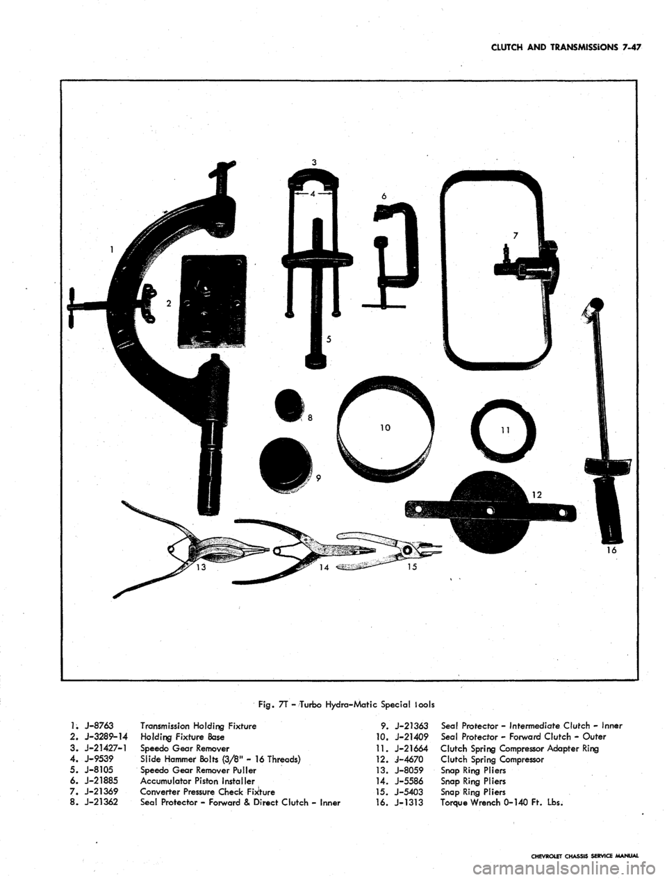
Fig.
7T - Turbo Hydro-Matic Special lools
1;
J-8763
2.
J-3289-14
3. J-21427-1
4.
J-9539
5. J-8105
6. J-21885
7. J-21369
8. J-21362
Transmission Holding Fixture
Holding Fixture Base
Speedo Gear Remover
Slide Hammer Bolts (3/8" - 16 Threads)
Speedo Gear Remover Puller
Accumulator Piston Installer
Converter Pressure Check Fixture
Seal Protector - Forward & Direct Clutch - Inner
9. J-21363
10.
J-21409
11.
J-21664
12.
J-4670
13.
J-8059
14.
J-5586
15.
J-5403
16.
J-1313
Seal Protector - Intermediate Clutch - Inner
Seal Protector - Forward Clutch - Outer
Clutch Spring Compressor Adapter Ring
Clutch Spring Compressor
Snap Ring Pliers
Snap Ring Pliers
Snap Ring Pliers
Torque Wrench 0-140 Ft. Lbs.
CHEVROLET CHASSIS SERVICE MANUAL
Page 411 of 659
FUEL TANK
AND
EXHAUST SYSTEMS
8-5
EXHAUST SYSTEMS
INDEX
Page
General Description
. . 8-5
Component Part Replacement
8-5
Muffler Assembly.
8-5
Exhaust Pipes.
8-5
Tail Pipes.
8-5
GENERAL DESCRIPTION
All exhaust systems used
on the 1967
Chevrolet
are
exhaust systems
(fig. 7) are
available
as
regular produc-
the split system type
in
which the. component parts
are
tion equipment
on the 427 cu. in.
displacement
V-8 en-
secured together with clamps.
The
single exhaust system gines
and as an
option
on the
other (except
283 cu. in.)
used
on L-6
engine models
(fig. 6)
consists
of an
exhaust
V-8
engines. These systems consist
of two
exhaust
pipe, muffler, tailpipe
and
attaching hardware.
On V-8
pipes, mufflers, tailpipes with resonators
and
attaching
engine single exhaust models
a
crossover pipe
is
added hardware.
All
exhaust systems
are
suspended on brackets
to connect
the
right exhaust manifold
to the
system. Dual with insulators
for
rattle free operation.
COMPONENT PART REPLACEMENT
Care should
be
taken
to
have
the
exhaust pipe, muffler
or tail pipe
in
proper relation with each other. Incorrect
alignment frequently causes annoying rattles
due to in-
correct clearances.
MUFFLER ASSEMBLY
Remove
and
Replace
1.
Remove "U" bolt clamp
at
center mounting.
2.
Remove
"U"
bolt clamp
at
forward
end of
muffler
pipe.
3.
Disengage muffler
at
exhaust
and
tail pipe
connections.
4.
Three-fourths inch clearance should
be
allowed
be-
tween
the
muffler bracket (hanger)
and
crossmember
at installation.
5. Install unit with
the
flat side
of the
muffler showing.
EXHAUST PIPE (CROSSOVER WITH
V-8
ENGINE)
Remove
and
Replace
1.
Remove
two
nuts, extension
and
packings-separate
pipe from manifold.
2.
3.
Disassemble
pipe.
"U"
damp from muffler
and
remove
Attach pipe
to
muffler, then secure
to
manifold. Note
clearances
for the
standard
and
automatic control
linkages, underbody
and
crossmember. Contact
of
exhaust pipe
to
engine panrail
is
permissible.
4.
Tighten nuts uniformly.
TAIL PIPE AND/OR RESONATOR
Remove
and
Replace
1.
Remove
"U"
clamp attachment
at
muffler.
2.
Remove screw attachment
at
tail pipe rear hanger
assembly.
3.
Remove tail pipe.
4.
Replace tail pipe
at
muffler, then install
at
hanger
Do
not
secure attachments until clearances have been
checked. Check position
of
hanger
so
that interplates
are parallel.
5. Torque nuts
7-9 ft. lbs. at
hanger
and 10-15 ft. lbs.
at muffler.
CHEVROLET CHASSIS
SEI
Page 442 of 659

STEERING 9-2
Fig.
1—Cover
Attaching Bolts—Chevy li Shown
ADJUSTMENTS
STEERING
GEAR
Before any adjustments are made to the steering gear
in an attempt to correct such conditions as shimmy,
loose or hard steering etc., a careful check should be
made of front end alignment, shock absorbers, wheel
balance and tire pressure for possible cause.
Correct adjustment of the steering gear is very im-
portant. Perform adjustments following the sequence
listed below,
1.
Remove pitman arm nut and mark relation of pitman
arm position to sector shaft. Remove pitman arm
with Tool J- 6632 as shown in Figure 2.
2.
Loosen the pitman shaft lash adjuster screw locknut
and turn the adjuster screw a few turns in a counter-
clockwise direction (fig. 3). This removes the load
Fig. 2—Removing Pitman Arm
imposed on the worm bearings by the close meshing
of rack and sector teeth. Turn steering wheel gently
in one direction until stopped by gear, then back away
about one turn.
CAUTION: Do not turn steering wheel hard
against stops when steering relay rod is discon-
nected as damage to ball guides may result.
3.
All except Corvette and telescopic columns:
a. Disconnect steering column harness at chassis
wiring connector plug.
b.
Remove horn cap or ornament and using an inch
pound torque wrench and socket on steering wheel
nut, measure torque required to keep the wheel
in motion.
LASH ADJUSTER
SCREW
LOCK NUT
WORM BEARING
ADJUSTER
\
WORM
ADJUSTER
Fig.
3—Steering Gear Adjustment Points
CHEVROLET CHASSIS SERVICE MANUAL
Page 443 of 659
STEERING 9-3
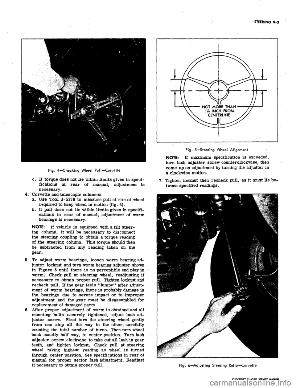
Fig.
4-Checking Wheel PuI!-Corvette
c. If torque does not lie within limits given in speci-
fications at rear of manual, adjustment is
necessary.
4.
Corvette and telescopic columns:
a. Use Tool J-5178 to measure.pull at rim of wheel
required to keep wheel in motion (fig. 4).
b.
If pull does not lie within limits given in specifi-
cations in rear of manual, adjustment of worm
bearings is necessary.
NOTE:
If vehicle is equipped with a tilt steer-
ing column, it will be necessary to disconnect
the steering coupling to obtain a torque reading
of the steering column. This torque should then
be subtracted from any reading taken on the
gear.
5. To adjust worm bearings, loosen worm bearing ad-
juster locknut and turn worm bearing adjuster shown
in Figure 3 until there is no perceptible end play in
worm. Check pull at steering wheel, readjusting: if
necessary to obtain proper pull. Tighten locknut and
recheck pull. If the gear feels "lumpy" after adjust-
ment of worm bearings, there is probably damage in
the bearings due to severe impact or to improper
adjustment and the gear must be disassembled for
replacement of damaged parts.
6. After proper adjustment of worm is obtained and all
mounting bolts securely tightened, adjust lash ad-
juster screw. First turn the steering wheel gently
from one stop all the way to the other, carefully
counting the total number of turns. Then turn wheel
back exactly half way, to center position. Turn lash
adjuster screw clockwise to take out all lash in gear
teeth, and tighten locknut. Check pull at steering
wheel taking highest reading as wheel is turned
through center position. See specifications in rear of
manual for proper sector lash adjustment. Readjust
if necessary to obtain proper pull.
NOT MORE THAN
T/a INCH FROM
CENTERLINE
Fig.
5—Steering Wheel Alignment
NOTE:
If maximum specification is exceeded,
turn las£ adjuster screw counterclockwise, then
come up on adjustment by turning the adjuster in
a clockwise motion.
7. Tighten locknut then recheck pull, as it must lie be-
tween specified readings.
Fig.
6—Adjusting Steering Ratio—Corvette
CHEVROLET CHASSIS SERVICE MANUAL
Page 444 of 659
STEERING 9-4
8. Reassemble pitman arm to sector shaft, lining up
marks made during disassembly. Refer to torque
specifications at rear of manual for correct torque
value.
9. Install horn cap or ornament and connect steering
column harness at chassis connector.
NOTE:
Chevy.n models are equipped with a
shim at the frame to steering gear mounting
bolts.
Shims may be removed or installed as
required for proper steering gear alignment.
STEERING WHEEL ALIGNMENT AND
HIGH POINT CENTERING
1.
Set front wheels in straight ahead position. This can
be checked by driving vehicle a short distance on a
flat surface to determine steering wheel position at
which vehicle follows a straight path.
2.
With front wheels set straight ahead, check position
of mark on wormshaft designating steering gear high
point. This mark should be at the top side of the shaft
at 12 o'clock position and lined up with the mark in
the coupling lower clamp.
3.
If gear has been moved off high point when setting
wheels in straight ahead position, loosen adjusting
sleeve clamps on both left and right hand tie rods,
then turn both sleeves an equal number of turns in
the same direction to bring gear back on high point.
CAUTION: Turning the sleeves an unequal
number of turns or in differential directions will
disturb the toe-in setting of the wheels.
4.
Readjust toe-in as outlined in Section 3 (if necessary).
5. With wheels in a straight ahead position and the
steering gear on highpoint, check the steering wheel
alignment by measuring the distance from each hori-
zontal spoke to the horizontal centerline of the
steering wheel (fig. 5). If the horizontal spokes are
over 1-1/8 inches from the horizontal position the
wheel should be removed and centered. (See steering
wheel removal in this section.)
TOE-IN ADJUSTMENT
Adjust the steering linkage for proper toe-in setting as
outlined in Section 3.
CORVETTE STEERING RATIO (Fig. 6)
The Corvette steering ratio may be changed as follows:
CAUTION: Do not use the rearward hole in the
steering arm with power steering equipment or
interference may result.
1.
Remove tie rod ball stud nut at steering arm and
disconnect tie rod from steering arm.
2.
Move tie rod end to forward hole for 17.6:1 ratio
(fast ratio) or rear hole for 20.2:1 ratio (standard
ratio).
3.
Install tie rod stud nut and tighten securely. Repeat
operation on opposite steering arm.
COMPONENT REPLACEMENT AND REPAIRS
STEERING WHEEL
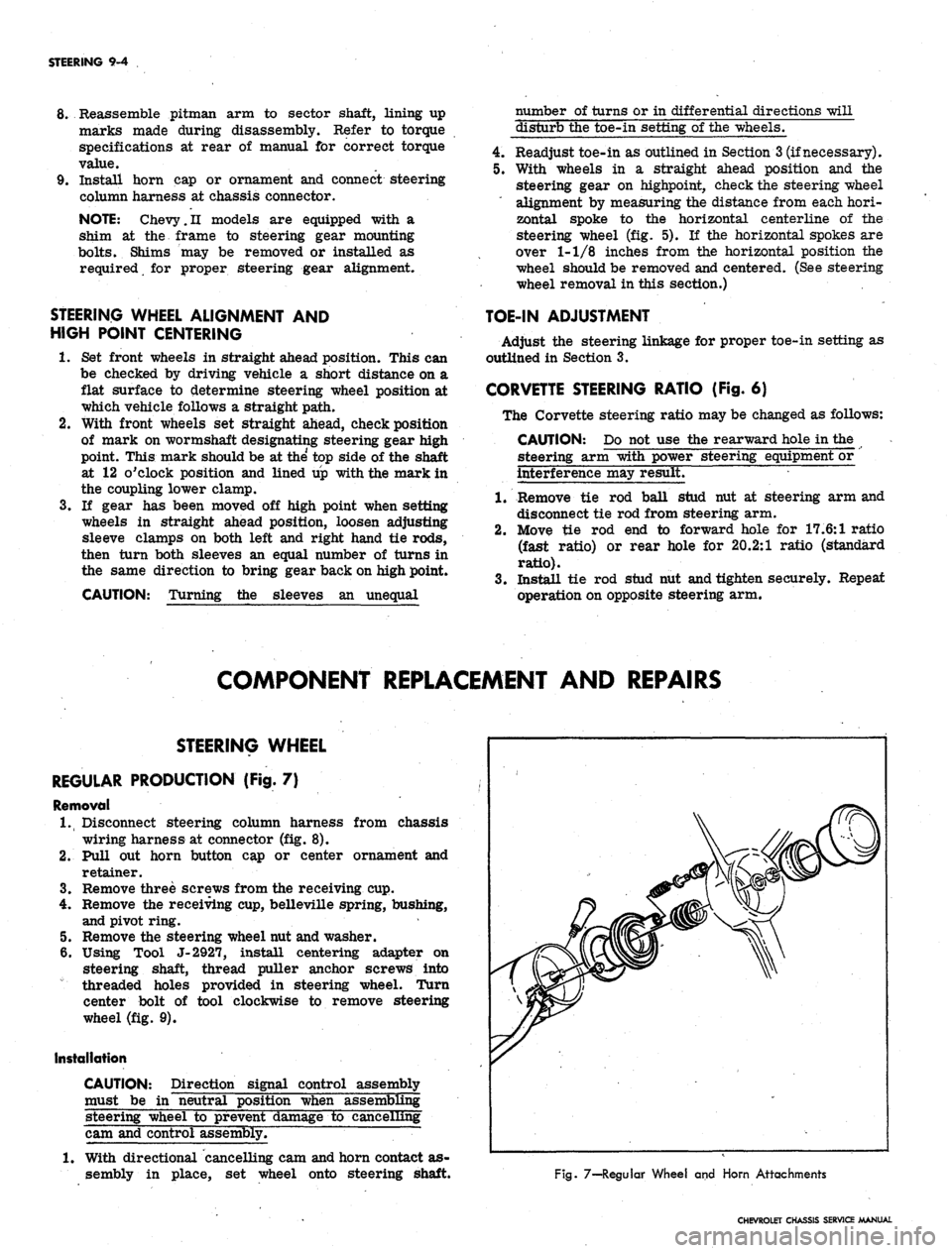
REGULAR PRODUCTION (Fig. 7)
Removal
1.
Disconnect steering column harness from chassis
wiring harness at connector (fig. 8).
2.
Pull out horn button cap or center ornament and
retainer.
3.
Remove three screws from the receiving cup.
4.
Remove the receiving cup, belleville spring, bushing,
and pivot ring.
5. Remove the steering wheel nut and washer.
6. Using Tool J-2927, install centering adapter on
steering shaft, thread puller anchor screws into
threaded holes provided in steering wheel. Turn
center bolt of tool clockwise to remove steering
wheel (fig. 9).
Installation
CAUTION: Direction signal control assembly
must be in "neutral position when assembling
steering wheel to prevent damage to cancelling
cam and control assembly.
1.
With directional cancelling cam and horn contact as-
sembly in place, set wheel onto steering shaft.
Fig. 7—-Regular Wheel and Horn Attachments
CHEVROLET CHASSIS SERVICE MANUAL
Page 445 of 659
STEERING 9-5
Fig.
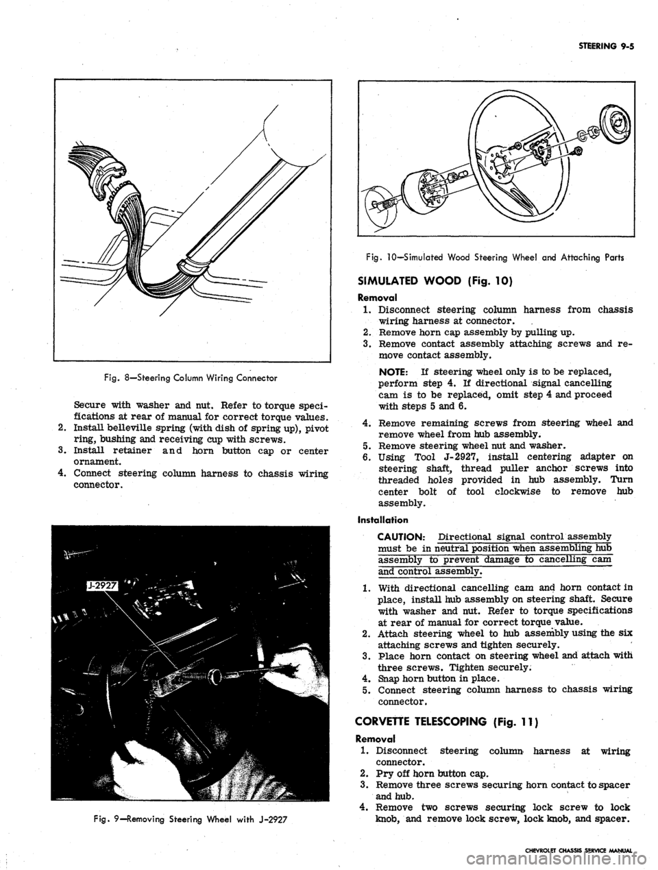
8—Steering Column Wiring Connector
Secure with washer and nut. Refer to torque speci-
fications at rear of manual for correct torque values.
Install belleville spring (with dish of spring up), pivot
ring, bushing and receiving cup with screws.
Install retainer and horn button cap or center
ornament.
Connect steering column harness to chassis wiring
connector.
Fig.
9—Removing Steering Wheel with J-2927
Fig.
10—Simulated Wood Steering Wheel and Attaching Parts
SIMULATED WOOD (Fig. 10)
Removal
1.
Disconnect steering column harness from chassis
wiring harness at connector.
2.
Remove horn cap assembly by pulling up.
3.
Remove contact assembly attaching screws and re-
move contact assembly.
NOTE:
If steering wheel only is to be replaced,
perform step 4. If directional signal cancelling
cam is to be replaced, omit step 4 and proceed
with steps 5 and 6.
4.
Remove remaining screws from steering wheel and
remove wheel from hub assembly.
5. Remove steering wheel nut and washer.
6. Using Tool J-2927, install centering adapter on
steering shaft, thread puller anchor screws into
threaded holes provided in hub assembly. Turn
center bolt of tool clockwise to remove hub
assembly.
Installation
CAUTION: Directional signal control assembly
must be in neutral position when assembling hub
assembly to prevent damage to cancelling cam
and control assembly.
1.
With directional cancelling cam and horn contact in
place, install hub assembly on steering shaft. Secure
with washer and nut. Refer to torque specifications
at rear of manual for correct torque value.
2.
Attach steering wheel to hub assembly using the six
attaching screws and tighten securely.
3.
Place horn contact on steering wheel and attach with
three screws. Tighten securely.
4.
Snap horn button in place.
5. Connect steering column harness to chassis wiring
connector.
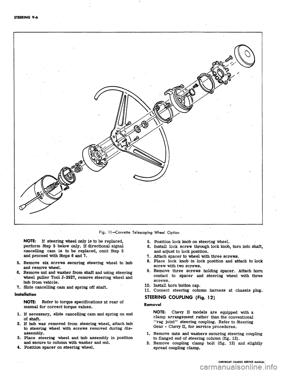
CORVETTE TELESCOPING (Fig. 11)
Removal
1.
Disconnect steering column harness at wiring
connector.
2.
Pry off horn button cap.
3.
Remove three screws securing horn contact to spacer
and hub.
4.
Remove two screws securing lock screw to lock
knob,
and remove lock screw, lock knob, and spacer.
CHEVROLET CHASSIS SERVICE MANUAL
Page 446 of 659
STEERING 9-6
Fig.
11
—Corvette Telescoping Wheel Option
5.
7.
NOTE:
If steering wheel only is to be replaced,
perform Step 5 below only. If directional signal
cancelling cam is to be replaced, omit Step 5
and proceed with Steps 6 and 7.
Remove six screws securing steering wheel to hub
and remove wheel.
Remove nut and washer from shaft and using steering
wheel puller Tool J-2927, remove steering wheel and
hub from vehicle.
Slide cancelling cam and spring off shaft.
Installation
NOTE:
Refer to torque specifications at rear of
manual for correct torque values.
1.
If necessary, slide cancelling cam and spring on end
of shaft.
2.
If hub was removed from steering wheel, attach hub
to steering wheel with screws removed during dis-
assembly.
3.
Place steering wheel and hub assembly in position
and secure to column with washer and nut.
4.
Position spacer on steering wheel.
5. Position lock knob on steering wheel.
6. Install lock screw through lock knob, turn into shaft,
and adjust to lock position.
7. Attach spacer to wheel with three screws.
8. Place lock knob in lock position and attach to lock
screw with two screws.
9. Remove three screws holding spacer. Attach horn
contact to spacer and steering wheel with three
screws.
10.
Install horn button cap.
11.
Connect steering column harness at chassis plug.
STEERING COUPLING (Fig. 12)
Removal
NOTE:
Chevy n models are equipped with a
clamp arrangement rather than the conventional
"rag joint" steering coupling. Refer to Steering
Gear - Chevy II, for service procedures.
1.
Remove nuts and washers securing steering coupling
to flanged end of steering column (fig. 12).
2.
Remove coupling clamp bolt (fig. 12) and slightly
spread coupling clamp.
CHEVROLET CHASSIS SERVICE MANUAL
Page 448 of 659
STEERING 9-8
DIAL
UPPER COVER
FASTENER
CHEVROLET
SCREW
CHEVELLE
Fig.
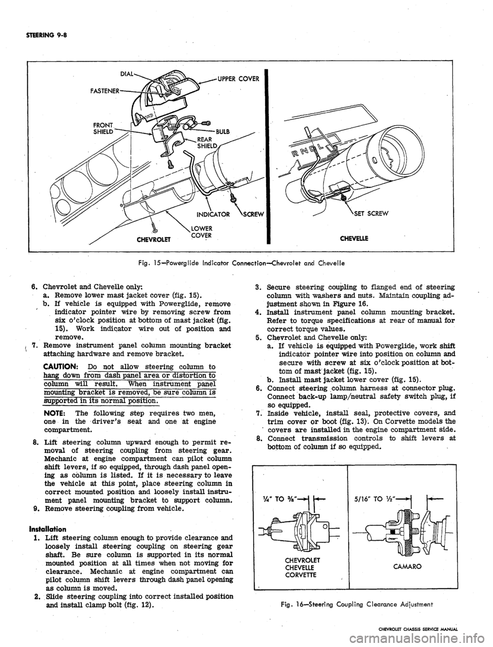
15—Powerglide Indicator Connection—Chevrolet and Chevelle
6.
Chevrolet and Chevelle only:
a. Remove lower mast jacket cover (fig. 15).
b.
If vehicle is equipped with Powerglide, remove
indicator pointer wire by removing screw from
six o'clock position at bottom of mast jacket (fig.
15).
Work indicator wire out of position and
remove.
Remove instrument panel column mounting bracket
attaching hardware and remove bracket.
CAUTION: Do not allow steering column to
hang down from dash panel area or distortion to
column will result. When instrument panel
mounting bracket is removed, be sure column is
supported in its normal position.
NOTE:
The following step requires two men,
one in the driver's seat and one at engine
compartment.
8
Lift steering column upward enough to permit re-
moval of steering coupling from steering gear.
Mechanic at engine compartment can pilot column
shift levers, if so equipped, through dash panel open-
ing as column is listed. If it is necessary to leave
the vehicle at this point, place steering column in
correct mounted position and loosely install instru-
ment panel mounting bracket to support column.
9. Remove steering coupling from vehicle.
Installation
1.
Lift steering column enough to provide clearance and
loosely install steering coupling on steering gear
shaft. Be sure column is supported in its normal
mounted position at all times when not moving for
clearance. Mechanic at engine compartment can
pilot column shift levers through dash panel opening
as column is moved.
2.
Slide steering coupling into correct installed position
and install clamp bolt (fig. 12).
3.
Secure steering coupling to flanged end of steering
column with washers and nuts. Maintain coupling ad-
justment shown in Figure 16.
4.
Install instrument panel column mounting bracket.
Refer to torque specifications at rear of manual for
correct torque values.
5. Chevrolet and Chevelle only:
a. If vehicle is equipped with Powerglide, work shift
indicator pointer wire into position on column and
secure with screw at six o'clock position at bot-
tom of mast jacket (fig. 15).
b.
Install mast jacket lower cover (fig. 15).
6. Connect steering column harness at connector plug.
Connect back-up lamp/neutral safety switch plug, if
so equipped.
7. Inside vehicle, install seal, protective covers, and
trim cover or boot (fig. 13). On Corvette models the
' covers are installed in the engine compartment side.
8. Connect transmission controls to shift levers at
bottom of column if so equipped.
CHEVROLET
CHEVELLE
CORVETTE
CAMARO
Fig.
16—Steering Coupling Clearance Adjustment
CHEVROLET CHASSIS SERVICE MANUAL