lock CHEVROLET CAMARO 1967 1.G Chassis Workshop Manual
[x] Cancel search | Manufacturer: CHEVROLET, Model Year: 1967, Model line: CAMARO, Model: CHEVROLET CAMARO 1967 1.GPages: 659, PDF Size: 114.24 MB
Page 383 of 659
CLUTCH AND TRANSMISSIONS 7-24
is at the full mark on the dip stick, it is just slightly be-
low the planetary gear unit. If additional oil is added,
bringing the oil level above the full mark, the planetary
unit will run in the oil, foaming and aerating the oil. This
aerated oil carried through the various oil pressure pas-
sages (low servo, reverse servo, clutch apply, converter,
etc.) may cause malfunction of the transmission assem-
bly, resulting in cavitation noise in the converter and
improper band or clutch application. Overheating may
also occur.
If the transmission is found consistently low on oil, a
thorough inspection should be made to find and correct
all external oil leaks.
PERIODIC OIL CHANGE
The transmission oil should be changed periodically as
recommended in Section 0, and whenever transmission is
to be removed from the vehicle for repairs.
1.
Run engine for one minute in neutral prior to chang-
ing.
2.
Be sure vehicle is level or raise from the rear only.
3.
Remove the oil pan drain plug and allow oil to drain
thoroughly into a pan or can.
Replace drain plug and refill with approximately two
quarts of oil specified in Section 0.
NOTE: To refill the transmission, remove dip
stick from oil filler tube and refill transmission
with oil specified in Section 0 using filler tube
and funnel J-4264. Then, after shifting into all
ranges at idle speed to fill all oil passages, the
engine should be run at 800-1000 rpm with the
transmission in Neutral until the oil warms up,
then add oil as required to raise the fluid level
to the full mark on the dip stick. Refill capacity
is approximately 2 qts.
4.
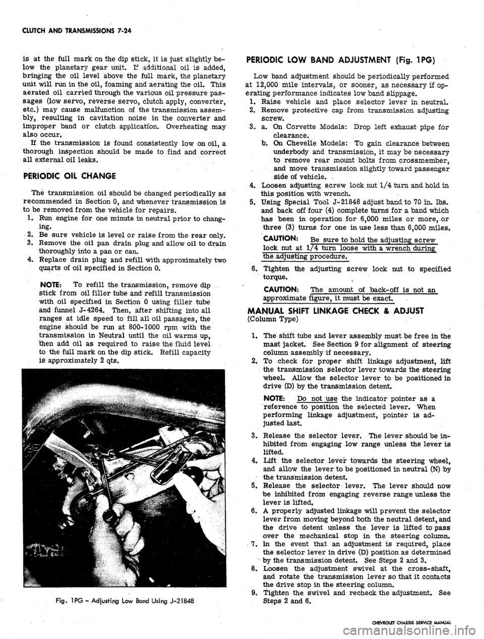
Fig.
1PG - Adjusting Low Band Using J-21848
PERIODIC LOW BAND ADJUSTMENT (Fig. 1PG)
Low band adjustment should be periodically performed
at 12,000 mile intervals, or sooner, as necessary if op-
erating performance indicates low band slippage.
1.
Raise vehicle and place selector lever in neutral.
2.
Remove protective cap from transmission adjusting
screw.
3.
a. On Corvette Models: Drop left exhaust pipe for
clearance.
b.
On Chevelle Models: To gain clearance between
underbody and transmission, it may be necessary
to remove rear mount bolts from crossmember,
and move transmission slightly toward passenger
side of vehicle. .
4.
Loosen adjusting screw lock nut 1/4 turn and hold in
this position with wrench.
5.
Using Special Tool J-21848 adjust band to 70 in. lbs.
and back off four (4) complete turns for a band which
has been in operation for 6,000 miles or more,.or
three (3) turns for one in use less than 6,000 miles.
CAUTION: Be sure to hold the adjusting screw
lock nut at 1/4 turn loose with a wrench during"
the.adjusting procedure.
6. Tighten the adjusting screw lock nut to specified
torque.
CAUTION: The amount of back-off is not an
approximate figure, it must be exact.
MANUAL SHIFT LINKAGE CHECK & ADJUST
(Column Type)
1.
The shift tube and lever assembly must be free in the
mast jacket. See Section 9 for alignment of steering
column assembly if necessary.
2.
To check for proper shift linkage adjustment, lift
the transmission selector lever towards the steering
wheel. Allow the selector lever to be positioned in
drive (D) by the transmission detent.
NOTE: Do not use the indicator pointer as a
reference to position the selected lever. When
performing linkage adjustment, pointer is ad-
justed last.
3.
Release the selector lever. The lever should be in-
hibited from engaging low range unless the lever is
lifted.
4.
Lift the selector lever towards the steering wheel,
and allow the lever to be positioned in neutral (N) by
the transmission detent.
5.
Release the selector lever. The lever should now
be inhibited from engaging reverse range unless the
lever is lifted.
6. A properly adjusted linkage will prevent the selector
lever from moving beyond both the neutral detent, and
the drive detent unless the lever is lifted to pass
over the mechanical stop in the steering column.
7.
In the event that an adjustment is required, place
the selector lever in drive (D) position as determined
by the transmission detent. See Steps 2 and 3.
8. Loosen the adjustment swivel at the cross-shaft,
and rotate the transmission lever so that it contacts
the drive stop in the steering column.
9. Tighten the swivel and recheck the adjustment. See
2 and 6.
CHEVROLET CHASSIS SERVICE MANUAL
Page 384 of 659
CLUTCH AND TRANSMISSIONS 7-25
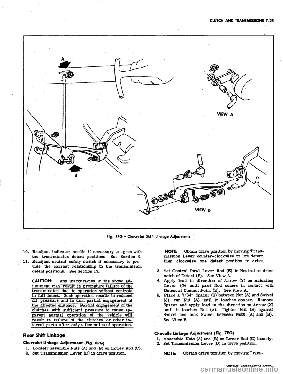
Fig.
2PG - Chevrolet Shift Linkage Adjustments
10.
11.
Readjust indicator needle if necessary to agree with
the transmission detent positions. See Section 9.
Readjust neutral safety switch if necessary to pro-
vide the correct relationship to the transmission
detent positions. See Section 12.
CAUTION: Any inaccuracies in the above ad-
justment may result in premature failure of the
transmission due to operation without controls
in full detent. Such operation results in reduced
oil pressure and in turn partial engagement of
the affected clutches. Partial
of the
clutches with sufficient pressure to cause ap-
parent normal operation of the vehicle will
result in failure of the clutches or other in-
ternal parts after only a few miles of operation.
Floor Shift Linkage
Chevrolet Linkage Adjustment (Fig. 6PG)
1.
Loosely assemble Nuts (A) and (B) on Lower Rod (C).
2.
Set Transmission Lever (D) in drive position.
NOTE:
Obtain drive position by moving Trans-
mission Lever counter-clockwise to low detent,
then clockwise one detent position to drive.
3.
Set Control Pawl Lever Rod (E) in Neutral or drive
notch of Detent (F). See View A.
4.
Apply load in direction of Arrow (Y) on Actuating
Lever (G) until pawl Rod comes in contact with
Detent at Contact Point (Z). See View A.
5. Place a 7/64" Spacer (H) between Nut (A) and Swivel
(J),
run Nut (A) until it touches spacer. Remove
Spacer and apply load in the direction on Arrow (X)
until it touches Nut (A). Tighten Nut (B) against
Swivel and lock Swivel between Nuts (A) and (B).
See View B.
Chevelle Linkage Adjustment (Fig. 7PG)
1.
Assemble Nuts (A) and (B) on Lower Rod (C) loosely.
2.
Set Transmission Lever (D) in drive position.
NOTE:
Obrain drive position by moving Trans-
CHEVROLET CHASSIS SERVICE MANUAL
Page 386 of 659
CLUTCH AND TRANSMISSIONS 7-27
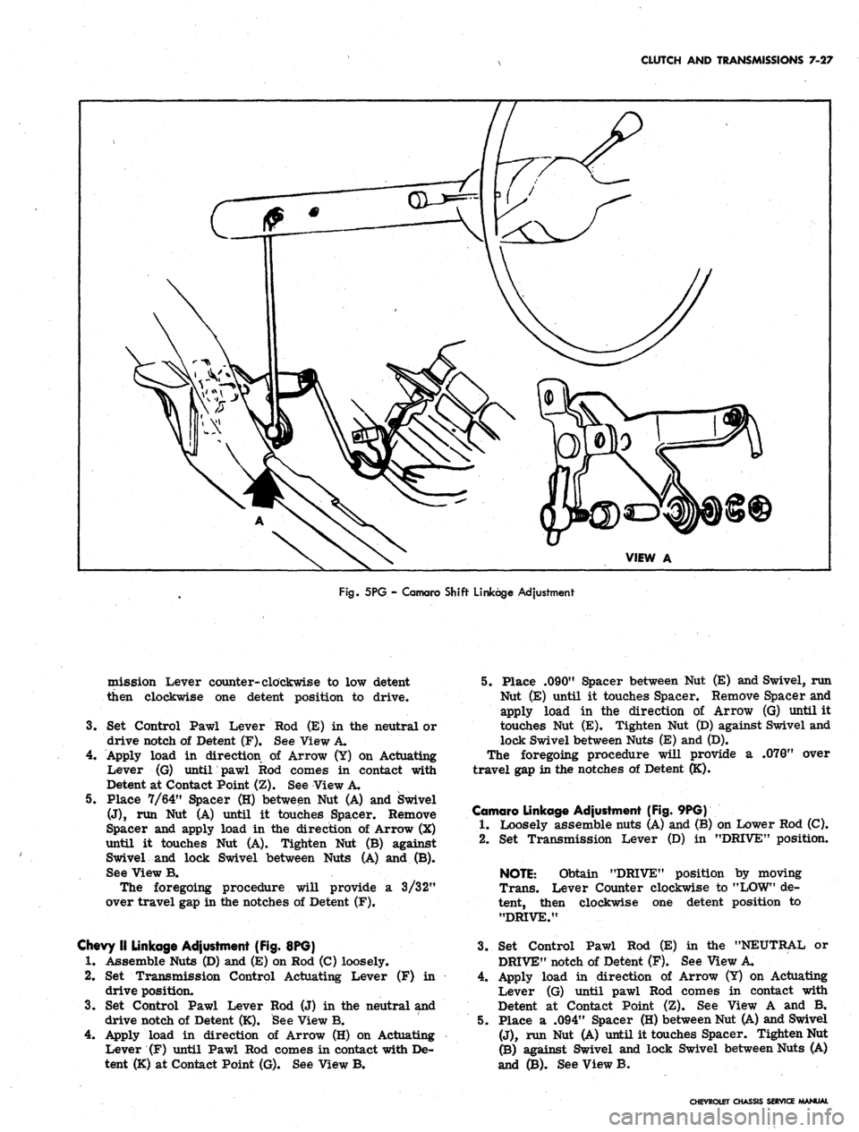
Fig.
5PG - Camaro Shift Linkage Adjustment
mission Lever counter-clockwise to low detent
then clockwise one detent position to drive.
3.
Set Control Pawl Lever
drive notch of Detent (F).
Rod (E) in the neutral or
See View A.
4.
Apply load in direction of Arrow (Y) on Actuating
Lever (G) until pawl Rod comes in contact with
Detent at Contact Point (Z). See View A.
5. Place 7/64" Spacer (H) between Nut (A) and Swivel
(J),
run Nut (A) until it touches Spacer. Remove
Spacer and apply load in the direction of Arrow (X)
until it touches Nut (A). Tighten Nut (B) against
Swivel and lock Swivel between Nuts (A) and (B).
See View B.
The foregoing procedure will provide a 3/32"
over travel gap in the notches of Detent (F).
Chevy II Linkage Adjustment (Fig. 8PG)
1.
Assemble Nuts (D) and (E) on Rod (C) loosely.
2.
Set Transmission Control Actuating Lever (F) in
drive position.
3.
Set Control Pawl Lever Rod (J) in the neutral and
drive notch of Detent (K). See View B.
4.
Apply load in direction of Arrow (H) on Actuating
Lever (F) until Pawl Rod comes in contact with De-
tent (K) at Contact Point (G). See View B.
5. Place .090" Spacer between Nut (E) and Swivel, run
Nut (E) until it touches Spacer. Remove Spacer and
apply load in the direction of Arrow (G) until it
touches Nut (E). Tighten Nut (D) against Swivel and
lock Swivel between Nuts (E) and (D).
The foregoing procedure will provide a .070" over
travel gap in the notches of Detent (K).
Camaro Linkage Adjustment (Fig. 9PG)
1.
Loosely assemble nuts (A) and (B) on Lower Rod (C).
2.
Set Transmission Lever (D) in "DRIVE" position.
NOTE:
Obtain "DRIVE" position by moving
Trans. Lever Counter clockwise to "LOW" de-
tent, then clockwise one detent position to
"DRIVE."
3.
Set Control Pawl Rod (E) in the "NEUTRAL or
DRIVE" notch of Detent (F). See View A.
4.
Apply load in direction of Arrow (Y) on Actuating
Lever (G) until pawl Rod comes in contact with
Detent at Contact Point (Z). See View A and B.
5. Place a .094" Spacer (H) between Nut (A) and Swivel
(J),
run Nut (A) until it touches Spacer. Tighten Nut
(B) against Swivel and lock Swivel between Nuts (A)
and (B). See View B.
CHEVROLET CHASSIS SERVICE MANUAL
Page 390 of 659
CLUTCH AND TRANSMISSIONS 7-31
with the "white" stripe painted on the engine
side of the flywheel outer rim, denoting the
"heavy" side of the engine.
1.
Mount transmission on transmission lifting equip-
ment installed on jack or other lifting device.
2.
Remove converter holding tool.
CAUTION: Do not permit converter to move
forward after removal of holding tool.
3.
Raise transmission into place at rear of engine and
install transmission case to engine upper mounting
bolts,
then install remainder of the mounting*bolts.
Torque bolts to 35 ft. lbs.
4.
Remove support from beneath engine, then raise
rear of transmission to final position.
5. Through flywheel cover opening align as closely as
possible the "white" flywheel balance mark stripe
and the "blue" painted stripe on the end of converter
cover and housing. If scribed during removal, align
scribe marks on flywheel and converter cover. In-
stall converter to flywheel attaching bolts. Torque
bolts to 15-20 ft. lbs.
6. Install converter under pan.
7. Reinstall transmission support crossmember to
transmission and frame.
8. Remove transmission lift equipment.
9. Connect propeller shaft to transmissions.
10.
Connect manual and TV control lever rods to
transmission.
11.
Connect oil cooler lines (if so equipped), vacuum
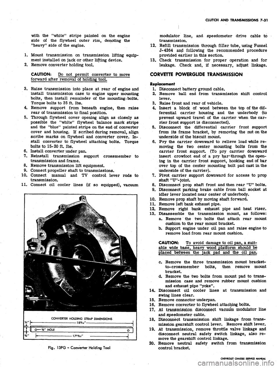
Fig.
13PG - Converter Holding Tool
modulato:* line, and speedometer drive cable to
transmission.
12.
Refill transmission through filler tube, using Funnel
J-4264 and following the recommended procedure
provided earlier in this section.
13.
Check transmission for proper operation and for
leakage. Check and, if necessary, adjust linkage.
CORVETTE POWERGLIDE TRANSMISSION
Replacement
1.
Disconnect battery ground cable.
2.
Remove ball end from transmission shift control
lever.
3.
Raise front and rear of vehicle.
4.
Insert a block of wood between the top of the dif-
ferential carrier housing and the underbody (to
prevent upward travel of the carrier when the car-
rier front support is disconnected).
5. Disconnect the differential carrier front support
from its frame bracket, by removing the nut on the
underside of the biscuit mount.
6. Pry the carrier downward to relieve load while re-
moving the two center mounting bolts from the
carrier front support. (To pry carrier downward
insert crowfoot end of a pry bar**hrough the open-
ing in the carrier front support, hooking end of bar
over top of the center mounting bolt pad cast in the
underside of the carrier).
7. Pivot carrier support downward for access to prop
shaft "U"-joint.
8. Disconnect prop shaft front and then rear
"U"
bolts.
9. Disconnect parking brake cable from ball socket at
idler lever located near center of underbody.
10.
Remove prop shaft by moving shaft forward.
11.
Remove left bank exhaust pipe.
12.
Remove right bank exhaust pipe and heat riser.
13.
Disassemble the transmission mount, as follows:
a. Remove the two bolts that attach rear mount
cushion to the rear mount bracket.
b.
Support engine under oil pan and raise engine to
remove load from rear mount cushion.
CAUTION: To avoid damage to oil pan, a suit-
able wide base, heavy wood platform should be
placed between the jack pad and the oil pan.
c. Remove the three transmission mount bracket-
to-crossmember bolts, then remove mount
bracket.
d. Remove the two bolts from mount pad to trans-
mission case and remove rubber mount cushion
and exhaust pipe "yoke".
14.
Disconnect oil cooler lines at transmission and
swing lines clear.
15.
Remove connector underpan.
16.
Remove converter to flywheel attaching bolts.
17.
At transmission disconnect vacuum modulator line
and speedometer cable.
18.
Disconnect transmission shift linkage from trans-
mission gearshift control lever. Remove shift lever.
19.
At transmission, remove throttle valve linkage and
disconnect neutral safety switch linkage, also re-
move the gearshift control linkage.
20.
Remove neutral safety switch from transmission
control bracket.
CHEVROLET CHASSIS SERVICE
Page 395 of 659
CLUTCH AND TRANSMISSIONS 7-36
TURBO HYDRA-MATIC TRANSMISSION
INDEX
Page
General Description . . , . 7-36
Maintenance and Adjustments . 7-37
Transmission Fluid 7-37
Fluid Level Indicator 7-37
Shift Control Linkage Adjustment ........... 7-37
Neutral Safety Switch Adjustment 7-37
Draining and Refilling Transmission . . . 7-37
Pressure Regulator Valve 7-38
Control Valve Body . 7-39
Governor ..'.... 7-40
Modulator and Modulator Valve 7-40
Parking Linkage . . 7-40
Page
Rear Seal -. 7-40
Other Service Operations . . 7-40
Transmission Replacement 7-40
Turbo Hydra-Matic Diagnosis Procedure. ......... 7-41
Sequence . ; ; 7-41
Oil Level and Condition Check 7-41
Manual Linkage 7-41
Oil Leaks .' 7-41
Case Porosity - Repair ................ 7-42
Oil Pressure Check 7-42
Transmission Shift Points 7-42
Special Tools 7-43
GENERAL DESCRIPTION
The Turbo Hydra-Matic transmission is a fully auto-
matic unit consisting primarily of a 3-element hydraulic
torque converter and a compound planetary gear set.
Three multiple-disc clutches, one sprag unit, one roller
clutch and two bands provide the friction elements re-
quired to obtain the desired function of the compound
planetary gear set.
The torque converter couples the engine to the plane-
tary gears through oil and provides hydraulic torque
multiplication when required. The compound planetary
gear set produces three forward speeds and reverse.
The
3-
element torque converter consists of a pump or
driving member, a turbine or driven member, and a
stator assembly. The stator is mounted on a one-way
roller clutch which will allow the stator to turn clock-
wise but not counter-clockwise.
The torque converter housing is filled with oil and
is attached to the engine crankshaft by a flex plate and
always rotates at engine speed. The converter pump is
an integral part of the converter housing, therefore the
pump blades, rotating at engine speed, set the oil within
the converter into motion and direct it to the turbine,
causing the turbine to rotate.
As the oil passes through the turbine it is traveling in
such a direction that if it were not re-directed by the
stator it would hit the rear of the converter pump blades
and impede its pumping action. So at low turbine speeds,
the oil is re-directed by the stator to the converter pump
in such a manner that it actually assists the converter
pump to deliver power or multiply engine torque.
As turbine speed increases, the direction of the oil
leaving the turbine changes and flows against the rear
side of the stator vanes in a clockwise direction. Since
the stator is now impeding the smooth flow of oil, its
roller clutch releases and it revolves freely on its shaft.
Once the stator becomes inactive, there is no further
multiplication of engine torque within the converter. At
this point, the converter is merely acting as a fluid
coupling as both the converter pump and turbine are
being driven at approximately the same speed - or at a
one-to-one ratio.
A hydraulic system pressurized by a gear type pump
provides the working pressure required to operate the
friction elements and automatic controls.
External control connections to transmission are:
Manual Linkage
Engine Vacuum
12 Volt Electrical
Signal
To select the desired op-
erating range.
To operate a vacuum mod-
ulator unit.
To operate an electrical
detent solenoid.
A vacuum modulator is used to automatically sense
any change in the torque input to the transmission. The
vacuum, modulator transmits this signal to the pressure
regulator for line pressure control, to the 1-2 accumula-
tor valve, and to the shift valves so that all torque re-
quirements of the transmission are met and smooth
shifts are obtained at all throttle openings.
The detent solenoid is activated by an alectric switch
on the carburetor. When the throttle is fully opened, the
switch on the carburetor is closed, activating the detent
solenoid and. causing the transmission to downshift at
speeds below approximately 70 MPH.
The selector quadrant has six selector positions: P,R,
N,D,
L2,L1.
P.
*
- Park position positively locks the output shaft to
the transmission case by means of a locking pawl
to prevent the vehicle from rolling in either di-
rection. The engine may be started in Park
position.
R. - Reverse enables the vehicle to be operated in a
reverse direction.
N.
- Neutral position enables the engine to be started
and run without driving the vehicle.
D,
- Drive Range is used for all normal driving condi-
tions and maximum economy. Drive Range has
three gear ratios, from the starting ratio to
direct drive. Detent downshifts are available by
depressing the accelerator to the floor.
L2.
- L2 Range has the same starting ratio as Drive
Range, but prevents the transmission from shift-
ing above second speed to retain second speed
acceleration when extra performance is desired.
L2 Range can also be used for engine braking.
L2 Range can be selected at any vehicle speed,
and the transmission will shift to second gear and
remain in second until the vehicle speed or the
throttle are changed to obtain first gear operation
in the same manner as in D Range.
CHIVROLET CHASSIS SERVICE MANUAL
Page 410 of 659
FUEL TANK AND EXHAUST SYSTEMS 8-4
Fig.
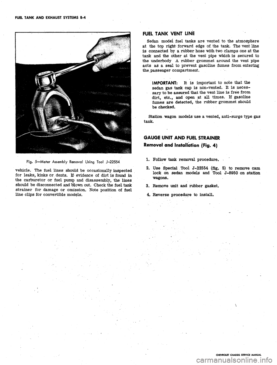
5— Meter Assembly Removal Using Tool J-22554
vehicle. The fuel lines should be occasionally inspected
for leaks, kinks or dents. If evidence of dirt is found in
the carburetor or fuel pumto and disassembly, the lines
should be disconnected
and
blown out. Check the fuel tank
strainer for damage or omission. Note position of fuel
line clips for convertible models.
FUEL TANK VENT LINE
Sedan modei fuel tanks are vented to the atmosphere
at the top right- forward edge of. the tank. The vent line
is connected by a rubber hose with two clamps one at the
tank and the other at the vent pipe which is secured to
the underbody A rubber grommet around the vent pipe
acts as a seal to prevent gasoline fumes from entering
the.passenger compartment.
IMPORTANT: It is important to note that the
sedan gas tank cap is non-vented. It is neces-
sary to be assured that the vent line is free from
dirt, etc., and open at all times. If gasoline
fumes are detected, the rubber grommet should
be checked.
Station wagon models use a vented, anti-surge type gas
tank.
GAUGE UNIT AND FUEL STRAINER
Removal and Installation (Fig. 4)
1.
Follow tank removal procedure.
2.
Use Special Tool J-22554 (fig. 5) to remove cam
lock on sedan models and Tool J-8950 on station
wagons.
3.
Remove unit and rubber gasket.
4.
Reverse procedure to install.
CHEVROLET CHASSIS SERVICE MANUAL
Page 414 of 659
FUEL TANK AND EXHAUST SYSTEMS
8-8
CHEVELLE
FUEL TANKS
INDEX
Page
General Description.
g.g
Component Part Replacement
8-8
Fuel Tanks
. 8-8
Fuel Lines
8-8
Metering Units (Gauge, Sending Unit)
Fuel Tank Filler Neck Caps.
. .
Fuel Tank Vent Lines
Page
8-8
8-8
8-9
GENERAL DESCRIPTION
All models
use a 20
gallon capacity (approx.) fuel tank
mounted between
the
frame rails behind
the
rear axle.
The fuel tanks
are
basically
the
same
for
sedan, 2-seat
station wagon
and
pickup models except
for
filler neck
location
and
venting
(fig. 8).
All fuel tanks
are
vented
to the
atmosphere. Sedan
model tanks have
an
external vent hose and pipe assem-
bly
(fig. 11) and use a
non-vented fuel cap. Station wagon
and pickup model tanks
are
vented through
a
hose
and
vent pipe assembly
to the
filler neck
(fig. 8)
and
use a
vented, anti-surge type
gas cap. The
fuel caps
are two
different designs conforming
to SAE
standards
and are
not interchangeable.
The filler neck assembly
on
sedan models
is a
rear
fill design located behind
the
center
bar of the
bumper.
Station wagon
and
sedan pickup model filler neck assem-
blies
are
located
in
the left rear quarter panel.
The fuel pickup pipe
is
built integrally with
the
tank
gauge, located
at the
top-front center
of
the tank.
A
fine
mesh screen
is
located
at
the bottom-end
of the
fuel pick-
up pipe
to
prevent
the
entrance
of
foreign material into
the fuel system.
The sedan fuel tanks
are
held
in
place
by
two metal
straps attached individually
to the
underbody
at
each
end.
The straps hinge
at the
forward end and secure
the
tank
at
the
rear with
an
adjustable bolt
and nut
assembly.
The station wagon
and
pickup models have
a
frame
mounted fuel tank secured with straps
to
front and rear
supports.
COMPONENT PART REPLACEMENT
FUEL TANK
Draining Tank
The absence
of a
drain plug
in the gas
tanks makes
it
necessary
to
siphon fuel from
the
tank when draining
is
needed. Refer
to the
recommended draining procedures
previously outlined under Chevrolet Models
in
this
section.
Removal
and
Installation (Sedan Models)
1.
Raise vehicle.
2.
Drain fuel tank.
3.
Disconnect fuel pickup line
and
gauge wires from
tank unit.
4.
Disconnect vent hose from tank.
5. Remove tank support straps and lower tank carefully.
6.
To
install, reverse
the
removal procedure.
Removal
and
Installation
(Station Wagon
and
Pickup)
1.
Follow Steps
1
thru
3
outlined under sedan models.
2.
Remove tank support straps.
3.
Remove frame screw attachments from
the
front
support
(fig. 8).
4.
Guide tank forward
and
remove.
5.
To
install, reverse removal procedure.
FUEL LINES
The fuel lines, extending from fuel tank toiiuelpump,
are routed
on the
underside
of the
underbody along
the
right side
of the
vehicle opposite
the
single exhaust
sys-
tem.
The
fuel lines should occasionally
be
inspected
for
leaks,
kinks,
or
dents.
If
evidence
of
dirt
is
found
in the
carburetor
or
fuel pump
on
disassembly,
the
lines should
be disconnected
and
blown
out.
Check
the
fuel tank
strainer
for
damage
or
omission. Fuel lines
are of 5/16"
diameter tubing with beaded type ends
for
connections
of
hoses.
FUEL PIPE RETAINER
CUP
Removal
and
Installation
If fuel pipes
and
retainer clips
are
removed, Tool
J-7777 should
be
used
to
install
new
retainer clips
(fig.
10).
After removal
of the old
clip from
the
frame, position
the
new
clip
in the
location
of the old
clip. Index
the
"blind rivet"
and
press hard (hand pressure should
do)
to expand rivet.
GAUGE UNIT
AND
FUEL STRAINER
Removal
and
Installation
(Fig. 11)
1.
Drain tank
to a
level below
the
unit.
2.
Disconnect fuel pickup line
and
gauge unit wire.
3.
Use
special Tool J-8950
to
remove
cam
lock.
Re-
move unit
and
rubber gasket.
CAUTION: Carefully remove unit
so as not to
damage screen
on the end of
the pipe.
4.
Clean screen
by
blowing
out
with compressed
air.
5. Reverse procedure
to
install.
FUEL TANK FILLER NECK CAPS
The fuel tank filler neck caps
are
non-vented with
an
anti-surge feature. Station wagons have vented caps.
(Refer
to
"Fuel Tank Vent Lines").
CHEVROLET CHASSIS SERVICE MANUAL
Page 419 of 659
FUEL TANK
AND
EXHAUST SYSTEMS
8-13
CHEVY II
FUEL TANKS
INDEX
Page
Page
General Description.
8-13
Component Part Replacement
8-13
Fuel Tanks
8-13
Fuel Lines
8-14
Metering Units (Gauge Sending Unit)
8-13
Fuel Tank Filler- Neck Caps.
. . 8-14
Fuel Tank Vent Lines .......
8-14
GENERAL DESCRIPTION
ANTI-SQUEAK
MA'
ANTI-SQUEAK
MATERIAL
SEDANS
STATION WAGON
Fig.
15-Chevy
II
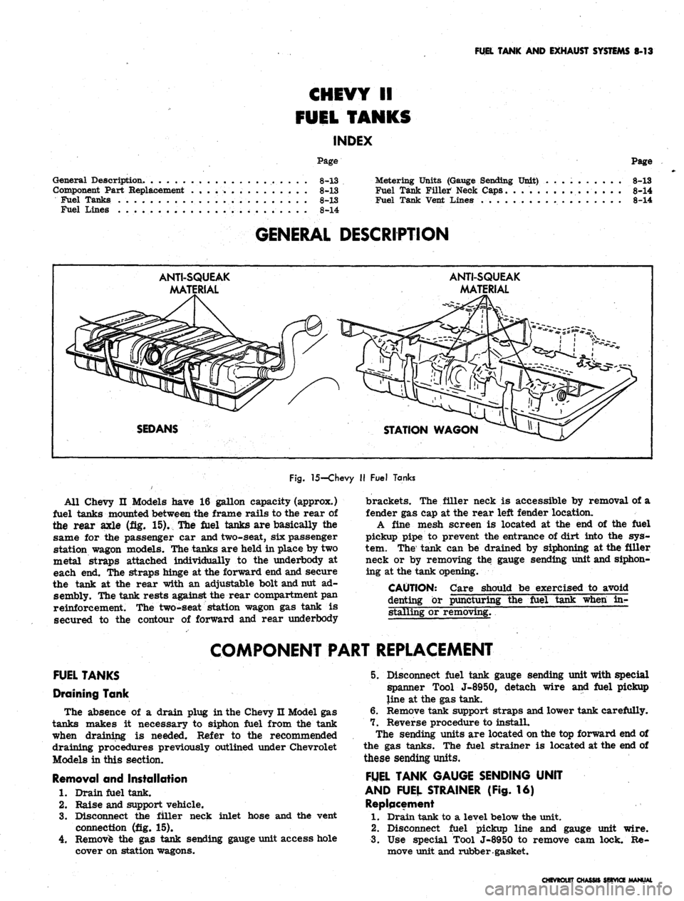
Fuel Tanks
All Chevy
II
Models have
16
gallon capacity (approx.)
fuel tanks mounted between
the
frame rails
to the
rear
of
the rear axle
(fig. 15). The
fuel tanks
are
basically
the
same
for the
passenger
car
and two-seat,
six
passenger
station wagon models. The tanks
are
held
in
place
by two
metal straps attached individually
to the
underbody
at
each
end. The
straps hinge
at the
forward
end
and secure
the tank
at the
rear with
an
adjustable bolt and nut
ad-
sembly. The tank rests against the rear compartment
pan
reinforcement.
The
two-seat station wagon
gas
tank
is
secured
to the
contour
of
forward
and
rear underbody
brackets.
The
filler neck
is
accessible
by
removal
of a
fender
gas cap at the
rear left fender location.
A fine mesh screen
is
located
at the end of the
fuel
pickup pipe
to
prevent
the
entrance
of
dirt into
the sys-
tem.
The
tank
can be
drained
by
siphoning
at the
filler
neck
or by
removing
the
gauge sending unit and siphon-
ing
at the
tank opening.
CAUTION: Care should
be
exercised
to
avoid
denting
or
puncturing
the
fuel tank when
in-
stalling
or
removing.
~
COMPONENT PART REPLACEMENT
FUEL TANKS
Draining Tank
The absence
of a
drain plug
in
the Chevy
n
Model
gas
tanks makes
it
necessary
to
siphon fuel from
the
tank
when draining
is
needed. Refer
to the
recommended
draining procedures previously outlined under Chevrolet
Models
in
this section.
Removal
and
Installation
1.
Drain fuel tank.
2.
Raise
and
support vehicle.
3.
Disconnect
the
filler neck inlet hose
and the
vent
connection
(fig. 15).
4.
Remove
the gas
tank sending gauge unit access hole
cover
on
station wagons.
5. Disconnect fuel tank gauge sending unit with special
spanner Tool J-8950, detach wire
and
fuel pickup
line
at the gas
tank.
6. Remove tank support straps and lower tank carefully.
7. Reverse procedure
to
install.
The sending units
are
located on
the top
forward
end of
the
gas
tanks.
The
fuel strainer
is
located
at the end of
these sending units.
FUEL TANK GAUGE SENDING UNIT
AND FUEL STRAINER
(Fig. 16)
Replacement
1.
Drain tank
to a
level below
the
unit.
2.
Disconnect fuel pickup line
and
gauge unit wire.
3.
Use
special Tool J-8950
to
remove
cam
lock.
Re-
move unit and rubber gasket.
CHEVROLET CHASSIS SERVICE MANUAL
Page 424 of 659
FUEL TANK
AND
EXHAUST SYSTEMS
8-18
CORVETTE
FUEL TANK
INDEX
Page
General Description.
. 8-18
Service Operations
8-18
Fuel Tank
8-18
Gauge Sending Unit
8-20
Fuel Lines.
8-20
GENERAL DESCRIPTION
20 GALLON TANK
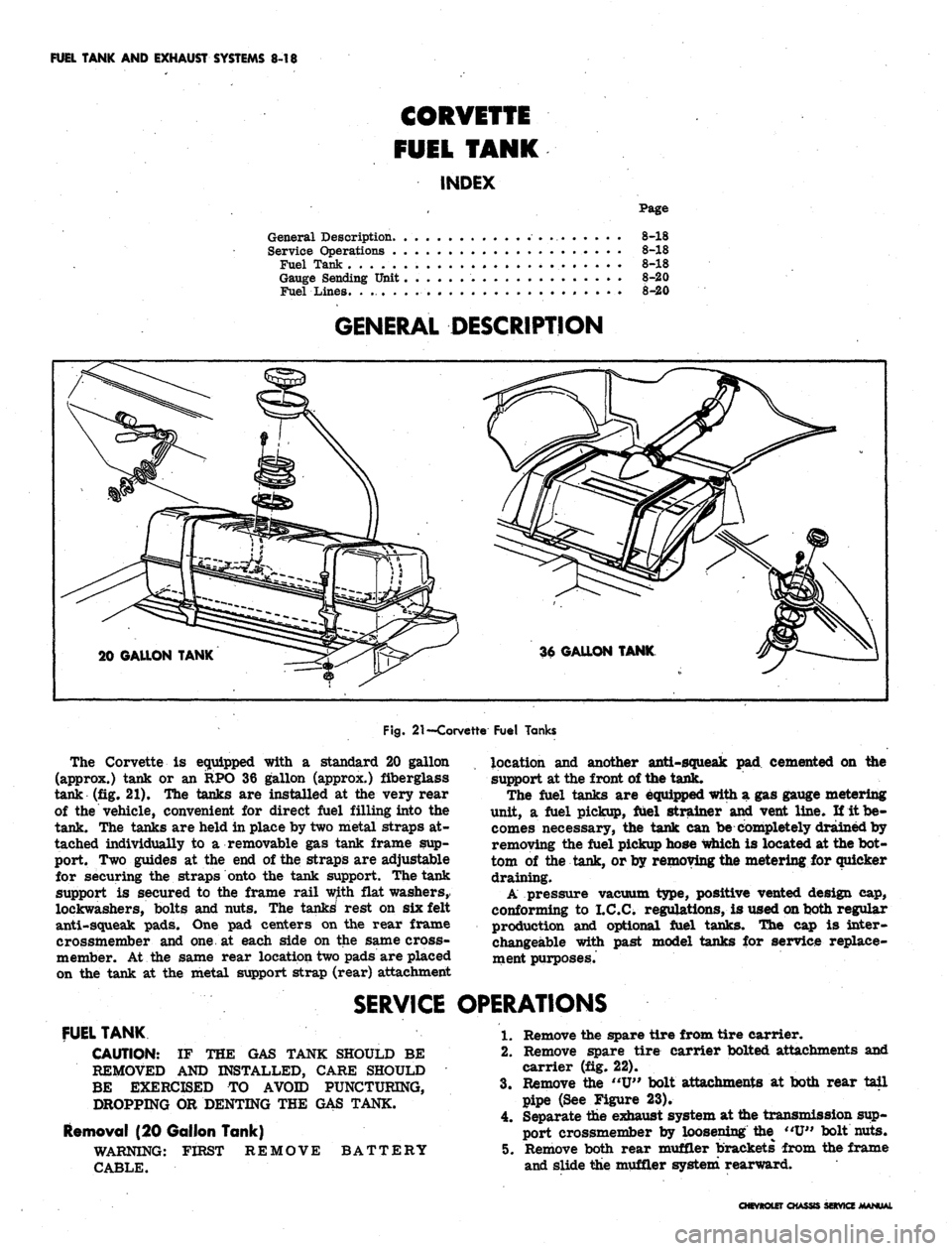
Fig.
21
—Corvette Fuel Tanks
The Corvette
is
equipped with
a
standard
20
gallon
(approx.) tank
or an RPO 36
gallon (approx.) fiberglass
tank
(fig. 21). The
tanks
are
installed
at the
very rear
of
the
vehicle, convenient
for
direct fuel filling into
the
tank.
The
tanks
are
held
in
place
by
two metal straps
at-
tached individually
to a
removable
gas
tank frame
sup-
port.
Two
guides
at the end of
the straps
are
adjustable
for securing
the
straps onto
the
tank support. The tank
support
is
secured
to the
frame rail with flat washers,
lockwashers, bolts
and
nuts.
The
tanks' rest
on six
felt
anti-squeak pads.
One pad
centers
on the
rear frame
crossmember
and one at
each side
on the
same cross-
member.
At the
same rear location two pads
are
placed
on
the
tank
at the
metal support strap (rear) attachment
location
and
another anti-squeak
pad
cemented
on the
support
at
the front
of
the tank.
The fuel tanks
are
equipped with
a gas
gauge metering
unit,
a
fuel pickup, fuel strainer
and
vent line.
If it be-
comes necessary,
the
tank
can be
completely drained
by
removing
the
fuel pickup hose which
is
located
at
the
bot-
tom
of the
tank,
or
by removing the metering
for
quicker
draining.
A pressure vacuum type, positive vented design
cap,
conforming
to
I.C.C. regulations,
is
used on both regular
production
and
optional fuel tanks.
The cap is
inter-
changeable with past model tanks
for
service replace-
ment purposes.
SERVICE OPERATIONS
FUEL TANK
CAUTION:
IF THE GAS
TANK SHOULD
BE
REMOVED
AND
INSTALLED, CARE SHOULD
BE EXERCISED
TO
AVOID PUNCTURING,
DROPPING
OR
DENTING
THE GAS
TANK.
Removal
(20
Gallon Tank)
WARNING: FIRST REMOVE BATTERY
CABLE.
1.
Remove
the
spare tire from tire carrier.
2.
Remove spare tire carrier bolted attachments
and
carrier
(fig. 22).
3.
Remove
the "U"
bolt attachments
at
both rear tail
pipe
(See
Figure
23).
4.
Separate
the
exhaust system
at
the transmission sup-
port crossmember
by
loosening
the "U"
bolt nuts.
5. Remove both rear muffler brackets from
the
frame
and slide
the
muffler system rearward.
CHEVROLET CHASSIS SERVICE MANUAL
Page 426 of 659
FUEL TANK AND EXHAUST SYSTEMS 8-20
4.
Attach the retaining straps with strap guide attached
to the fuel tank support, and secure with-the nut and
lockwasher assembly.
5. Connect the filler neck boot to the drain hose of the
tank and install boot around filler neck,
6. Connect the fuel pickup line, ground wire and make
certain that the fuel drain line is flush to 1/2" in-
board of the rear bumper opening.
7. Attach tank metering unit wires (fig. 25).
8. Replace fuel in tank. Replace gas cap.
9. Check for possible leaks.
10.
Reconnect the exhaust system by reversing the above
removal procedures (see "Exhaust System").
11.
Install spare tire carrier by securing the bolt
attachment.
12.
Install the spare tire in the tire carrier.
Removal (36 Gallon Tank)
1.
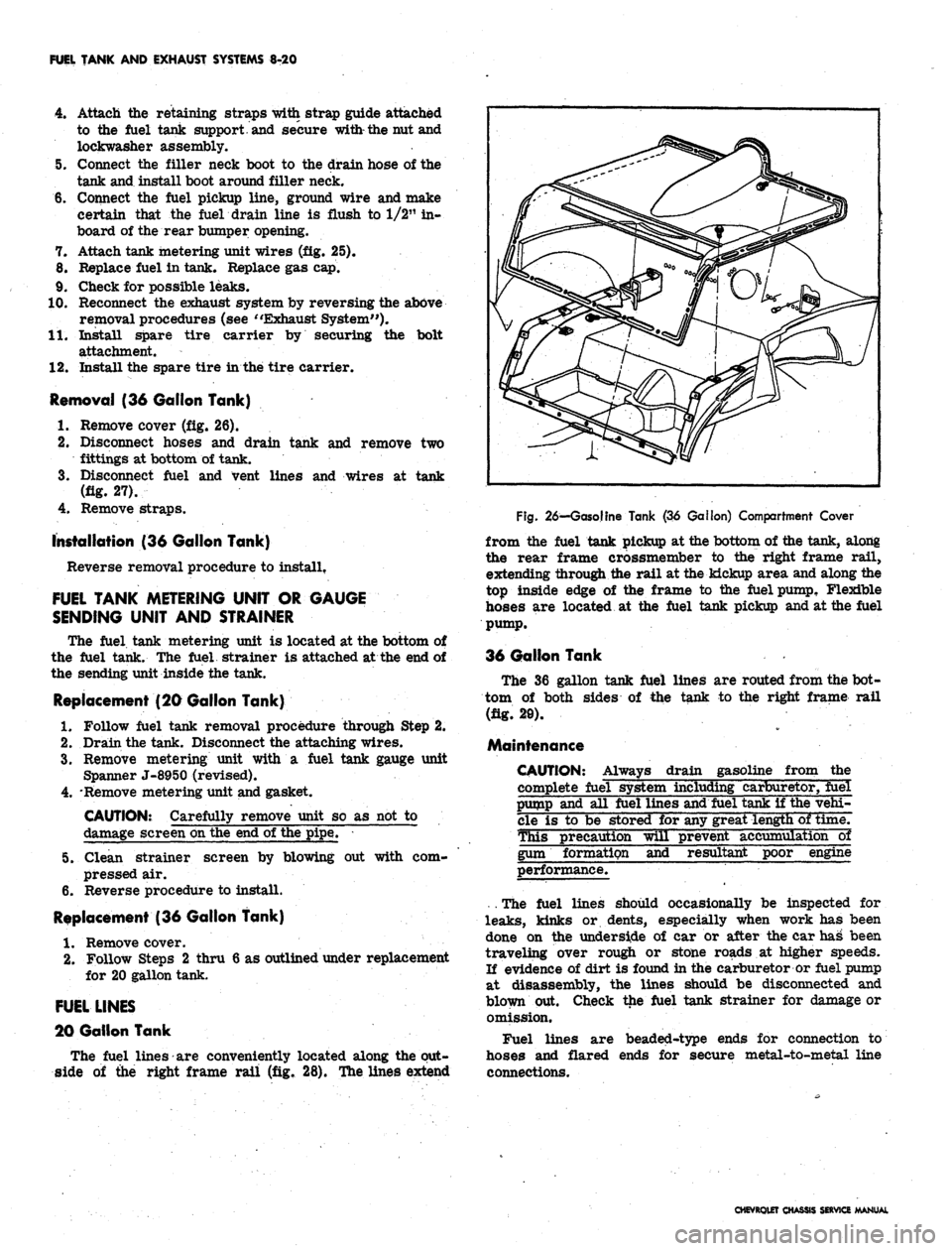
Remove cover (fig. 26).
2.
Disconnect hoses and drain tank and remove two
fittings at bottom of tank.
3.
Disconnect fuel and vent lines and wires at tank
(fig. 27).
4.
Remove straps.
installation (36 Gallon Tank)
Reverse removal procedure to install.
FUEL TANK METERING UNIT OR GAUGE
SENDING UNIT AND STRAINER
The fuel tank metering unit is located at the bottom of
the fuel tank. The fuel strainer is attached at the end of
the sending unit inside the tank.
Replacement (20 Gallon Tank)
1.
Follow fuel tank removal procedure through Step 2.
2.
Drain the tank. Disconnect the attaching wires.
3.
Remove metering unit with a fuel tank gauge unit
Spanner J-8950 (revised).
4.
'Remove metering unit and gasket.
CAUTION: Carefully remove unit so as not to
damage screen on the end of the pipe.
5. Clean strainer screen by blowing out with com-
pressed air.
6. Reverse procedure to install.
Replacement (36 Gallon Tank)
1.
Remove cover.
2.
Follow Steps 2 thru 6 as outlined under replacement
for 20 gallon tank.
FUEL LINES
20 Gallon Tank
The fuel lines are conveniently located along the out-
side of the right frame rail (fig. 28). The lines extend
Fig.
26—Gasoline Tank (36 Gallon) Compartment Cover
from the fuel tank pickup at the bottom of the tank, along
the rear frame crossmember to the right frame rail,
extending through the rail at the kickup area and along the
top inside edge of the frame to the fuel pump, Flexible
hoses are located at the fuel tank pickup and at the fuel
pump.
36 Gallon Tank
The 36 gallon tank fuel lines are routed from the bot-
tom of both sides of the tank to the right frame rail
(fig. 20).
Maintenance
CAUTION: Always drain gasoline from the
complete fuel system including carburetor, fuel
pump and all fuel lines and fuel tank if the vehi-
cle is to be stored for any great length of time.
This precaution will prevent accumulation~ol
gum formation and resultant poor engine
performance.
. The fuel lines should occasionally be inspected for
leaks,
kinks or dents, especially when work has been
done on the underside of car or after the car has been
traveling over rough or stone roads at higher speeds.
If evidence of dirt is found in the carburetor or fuel pump
at disassembly, the lines should be disconnected and
blown put. Check the fuel tank strainer for damage or
omission.
Fuel lines are beaded-type ends for connection to
hoses and flared ends for secure metal-to-metal line
connections.
CHEVROLET CHASSIS SERVICE MANUAL