CHEVROLET CAMARO 1967 1.G Chassis Owner's Manual
Manufacturer: CHEVROLET, Model Year: 1967, Model line: CAMARO, Model: CHEVROLET CAMARO 1967 1.GPages: 659, PDF Size: 114.24 MB
Page 21 of 659
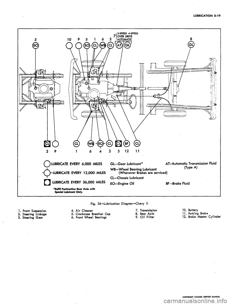
LUBRICATION
0-19
.
3-SPEED
4-SPEED
7 OVER DRIVE
10 9 5 1 6 2 '
AUTOMATIC
3 12 11
LUBRICATE EVERY 6,000 MILES GL-Gear Lubricant*
WB-Wheel Bearing Lubricant
(Wh Bk
AT-Automdtic Transmission Fluid
^ WB-Wheel Bearing Lubricant (Type A)
-TV
LUBRICATE
EVERY 12,000 MILES (Whenever Brakes are serviced)
' CL—Chassis Lubricant
• LUBRICATE EVERY 36,000 MILES EO_Engine Oil
BF
-Brake Fluid
•Refill Positt
Special Lubricant Only.
Axl«
with
1.
Front Suspension
2.
Steering Linkage
3. Steering Gear
Fig.
34—Lubrication Diagram—Chevy I!
4. Air Cleaner
5. Crankcase Breather. Cap
6. Front Wheel Bearings
7. Transmission
8. Rear Axle
9.
Oil Filter
10.
Battery
11.
Parking Brake
12.
Brake Master Cylinder
CHEVROLET CHASSIS SERVICE MANUAL
Page 22 of 659
LUBRICATION 0-20
3-SPEED
4—SPEED
AUTOMATIC
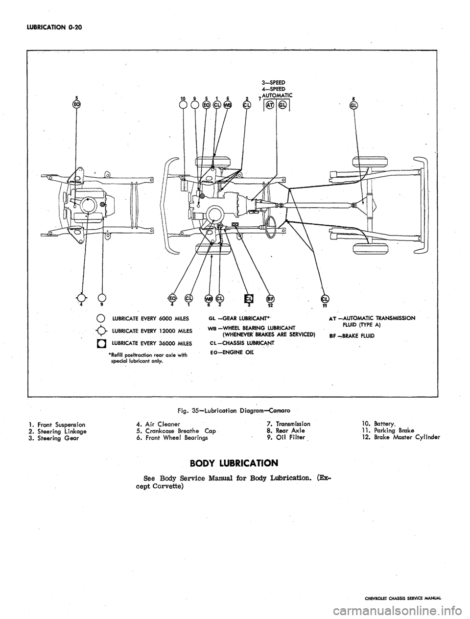
LUBRICATE EVERY 6000 MILES
LUBRICATE EVERY 12000 MILES
LUBRICATE EVERY 36000 MILES
*
Refill
positraction rear axle with
special lubricant only.
GL -GEAR LUBRICANT*
WB-WHEEL BEARING LUBRICANT
(WHENEVER BRAKES
ARE
SERVICED)
CL -CHASSIS LUBRICANT
CO-ENGINE
Oil;
AT -AUTOMATIC TRANSMISSION
FLUID (TYPE
A)
BF -BRAKE FLUID
Fig.
35—Lubricafion Diagram—Camaro
1.
Front Suspension
2.
Steering Linkage
3. Steering Gear
4.
Air Cleaner
5. Crankcase Breathe Cap
6. Front Wheel Bearings
7. Transmission
8. Rear Axle
9. Oil Filter
10.
Battery,
11.
Parking Brake
12.
Brake Master Cylinder
BODY LUBRICATION
See Body Service Manual
for
Body Lubrication,
cept Corvette)
(Ex-
CHEVROLET CHASSIS SERVICE MANUAL
Page 23 of 659
LUBRICATION
0-21
6
3-SPEED
4-SPEED
AUTOMATIC
10
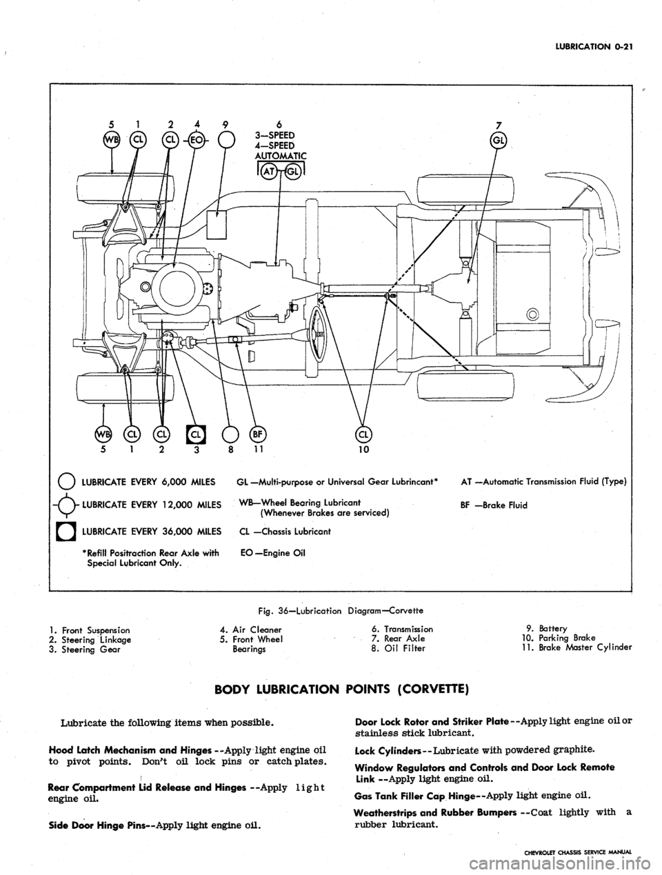
LUBRICATE EVERY 6,000 MILES GL -Multi-purpose
or
Universal Gear Lubrincant*
-(V LUBRICATE EVERY 12,000 MILES WB-Wheel Bearing Lubricant
V/^ (Whenever Brakes
are
serviced)
AT —Automatic Transmission Fluid (Type)
BF -Brake Fluid
a
LUBRICATE EVERY 36,000 MILES
* Refill Positraction Rear Axle with
Special Lubricant Only.
CL -Chassis Lubricant
EO—Engine
Oil
Fig.
36—Lubrication Diagram—Corvette
1.
Front Suspension
2.
Steering Linkage
3. Steering Gear
4.
Air
Cleaner
5. Front Wheel
Bearings
6. Transmission
7. Rear Axle
8.
Oil
Filter
9. Battery
10.
Parking Brake
11.
Brake Master Cylinder
BODY LUBRICATION POINTS (CORVETTE)
Lubricate the following items when possible.
Hood Latch Mechanism and Hinges --Apply light engine oil
to pivot points. Don't oil lock pins or catch plates.
i
Rear Compartment Lid Release and Hinges --Apply light
engine
oil.
Side Door Hinge Pins—Apply light engine oil.
Door Lock Rotor and Striker Plate—Apply light engine oil or
stainless stick lubricant.
Lock Cylinders—Lubricate with powdered graphite.
Window Regulators and Controls and Door Lock Remote
Link —Apply light engine
oil.
Gas Tank Filler Cap Hinge—Apply light engine oil.
Weatherstrips and Rubber Bumpers —Coat lightly with
a
rubber lubricant.
CHEVROLET CHASSIS SERVICE MANUAL
Page 24 of 659
SECTION
1A
HEATER
AND AIR
CONDITIONING
CONTENTS
OF
THIS SECTION
Heater
Air Conditioning
Page
1A-1
1A-13
HEATER
GENERAL DESCRIPTION
CHEVROLET, CHEVELLE,
AND
CAMARO
Components
of the
Chevrolet, Chevelle,
and
Camero
heaters
are
attached
to the
firewall
on the
right side
of
the vehicle. The blower
and air
inlet assembly and water
hoses
are
located on the engine side
of
the firewall while
the heater core and distributor duct
are on the
passenger
side.
The heater operates
on
outside
air
only with
the
blower receiving
its
airflow from
the
cowl vent plenum
chamber.
Since
the
unit
has no
water valve, water circulation
keeps
the
core
hot at all
times.
Air
passing through
the
core receives maximum heat from
the
core.
In operation, three levers control
all
heater opera-
tions.
The
AIR-FAN lever
is a
combination control;
moving
the
lever half-way opens
the
AIR door
(by
means
of
a
bowden cable)
to
supply outside
air to the
three
speed blower. Further movement
of the
lever operates
the blower.
The
other levers depend on bowden cables
to
operate
the
diverter doors located
in the
distributor
duct
to
control heater output and operation.
At
the
heart
of
the heater operation
is the
temperature
door.
Air
from
the
blower follows parallel paths through
the distributor duct, with
one
path passing through
the
heater core
and the
other path bypassing
the
core.
The
temperature door, operated
by the
TEMPERATURE
con-
trol lever,
is
placed
in the
duct
so
that when
it
closes
off
the path from
the
heater core,
it
allows ambient airflow
through
the
unheated path.
In the
opposite position only
heated airflow
is
allowed. Final heater output tempera-
ture
is
dependent upon
the
proportion
of
heated
and
unheated
air
blended together according
to the
setting
of
this temperature door.
To
insure positive closing
of
this
door when
the
heat lever
is in the off
position,
a cam
lock device
is
utilized
in the
control linkage
of the
Chevelle heater only.
Just beyond
the
temperature damper door
is the Air
door, operated
by the
AIR-FAN control lever, which
is
the
air
on-or-off control. This door will
be
open when-
ever
the
heater blower
is in
operation.
The defroster door, operated
by the
DEFROSTER
lever, acts
to
divert
the
heated
air
flow
up
through
the
defroster ducts
for
de-fogging, defrosting
or
de-icing
operations.
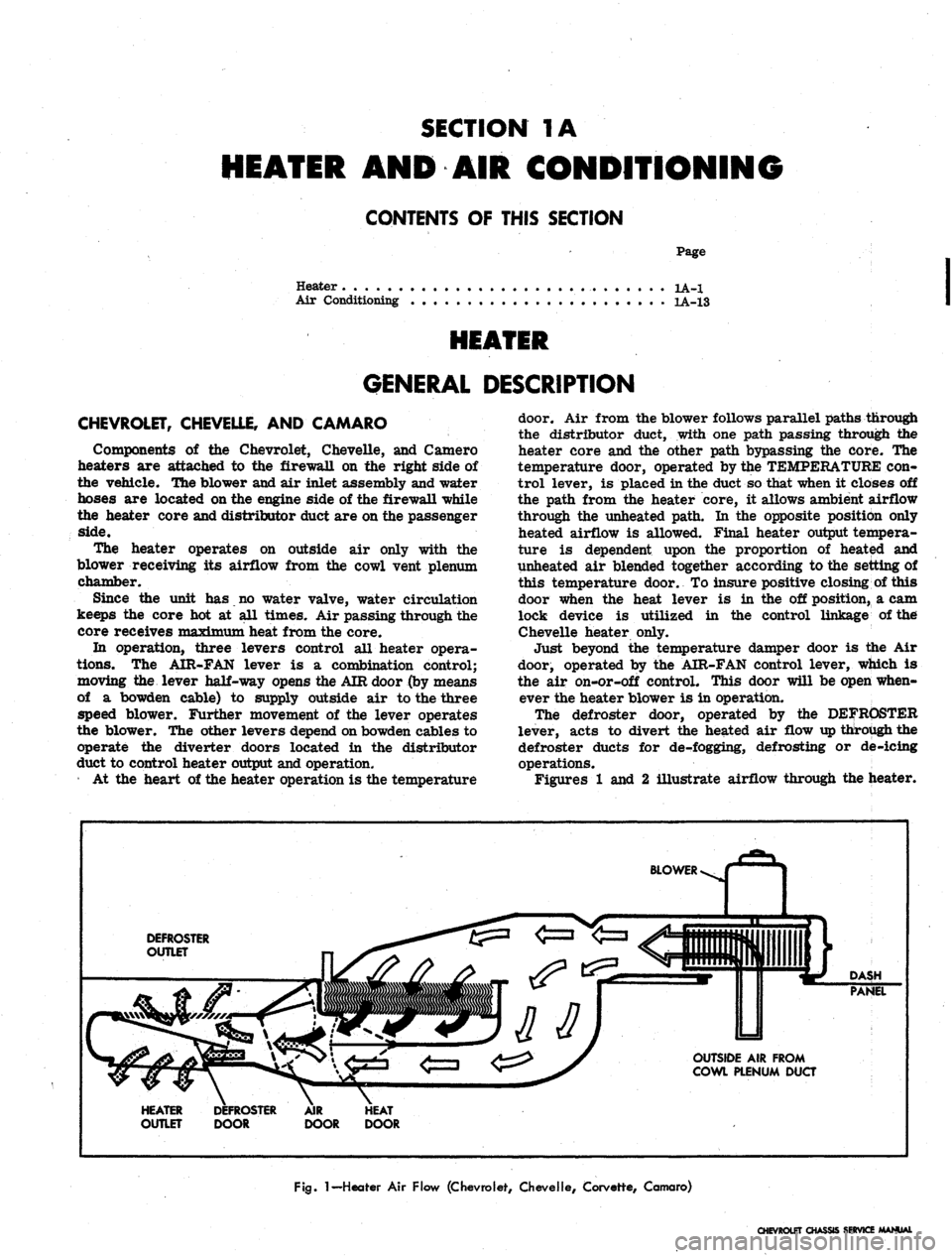
Figures
1 and 2
illustrate airflow through
the
heater.
BLOWER
DEFROSTER
OUTLET
DASH
PANEL
OUTSIDE
AIR
FROM
COWL PLENUM DUCT
HEATER
OUTLET
DOOR
DOOR
Fig.
1
— Heater
Air
Flow (Chevrolet, Chevelle, Corvette, Camaro)
CHEVROLET CHASSIS SERVICE MANUAL
Page 25 of 659
HEATER AND AIR CONDITIONING 1A-2
DEFROSTER-q
DOOR
v-
HEATER
OUTLET
DEFROSTER
OUTSIDE
AIR
FROM PLENUM
OUTLETS
""•—
,
BLOWER
« 1
/ y
r J
\
AIR
DUQ
•*-——
DOOR
—-**
X J
HEAT
DOOR
HEATER
CORE
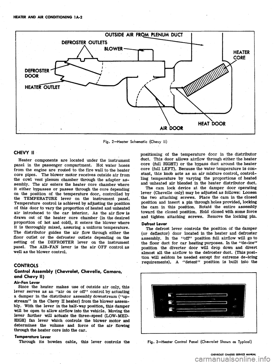
Fig. 2-Heater Schematic (Chevy 11)
CHEVY
II
Heater components are located under the instrument
panel in the passenger compartment. Hot water hoses
from the engine are routed to the fire wall to the heater
core pipes. The blower motor receives outside air from
the cowl vent plenum chamber through the adapter as-
sembly. The air enters the heater core chamber where
it either bypasses or passes through the core depending
on the position of the temperature door, controlled by
the TEMPERATURE lever on the instrument panel.
Temperature control is achieved by adjusting the position
of this door to vary the proportion of heated and unheated
air introduced to the car interior. As the air flow is
drawn out of the heater core chamber (in the desired
proportion of hot and cold), it enters the blower where
it is thoroughly mixed, assuring a uniform temperature.
The distributor guides the air flow through either the
floor outlet or the defroster outlets depending on the
setting of the DEFROSTER lever on the instrument
panel. The AIR-FAN lever is the air OFF control as
well as the blower control.
CONTROLS
Control Assembly (Chevrolet, Chevelle, Camaro,
and Chevy II)
Air-Fan Lever
Since the heater makes use of outside air only, this
lever serves as an "air on or off" control by actuating
a damper in the distributor assembly downstream ("up-
stream" in the Chevy n heater) from the blower assem-
bly. With the lever in the half-way position, this damper
will be open to allow airflow into the vehicle. Moving the
lever further will actuate the three-speed (LOW-MED-
HIGH) fan lever which controls the blower motor and
determines the volume and force of the air flowing
through the heater core into the car.
Temperature Lever
Through its bowden cable, this lever controls the
positioning of the temperature door in the distributor
duct. This door allows airflow through either the heater
core (full RIGHT) or the bypass duct around the heater
core (full LEFT). Because the water temperature is con-
stant, this knob acts as an air mixture control, control-
ling temperature by varying the proportions of heated
and unheated air blended in the heater distributor duct.
The cam lock device at the damper door operating
lever (Chevelle only) may be adjusted as follows: Loosen
the two attaching screws. Place the cam in the closed
position and insert a pin through holes provided, locking
the cam in this position. Rotate the entire assembly
toward the closed position. Hold closed with some force
and tighten attaching screws. Remove the locking pin.
Defrost Lever
The defrost lever controls the position of the damper
(or deflector) door located in the heater and defroster
assembly. In the "off" position full airflow will go to
the floor duct for car heating purposes. In the "de-ice"
position the diverter door will drop down and divert
almost all the airflow to the defroster duct. (This posi-
tion will seldom be needed except for extreme de-icing
requirements). A "detent" position is built into the
Fig. 3—Heater Control Panel (Chevrolet Shown as Typical)
CHEVROLET CHASSIS SERVICE MANUAL
Page 26 of 659
HEATER AND AIR CONDITIONING 1A-3
linkage of this lever which will provide partial airflow
only to the defroster duct and which should be used for,
all normal defogging operations.
CORVETTE
Heater components are attached to the dash panel on
the right side of the vehicle with the air inlet assembly
on the engine side and the heater and air distributor
assemblies beneath the instrument panel within the pas-
senger compartment.
The heater operates on outside air only with the blower
receiving its air flow from the cowl vent plenum
chamber.
No water valve is utilized in the system. Therefore,
water flows through the heater core constantly while
the engine is running, keeping the core at maximum
temperature at all times.
Airflow through the system is shown in Figure 1.
Controls
Two knobs control all heater operations:
The FAN-TEMP knob is rotated to turn the blower
on and off and control blower speed and is pulled out
as desired to regulate heater temperature.
The AIR-DEF knob is the air on-and-off control as
well as the defroster control.
Temperature Damper: Door
At the heart of the heater operation is the temperature
damper door. Air from the blower follows parallel paths
through the distributor duct, with one path passing
through the heater core and the other path bypassing the
core.
The temperature damper door is placed in the duct
so that, when closed, the path of the heated air leaving
the heater core is blocked while the ambient air path
remains open. Positive closing of this door when no
heat is being called for is assured by a cam assembly
at the door operating lever. As the FAN-TEMP knob
is pulled out, the damper door is opened accordingly,
allowing varying proportions of heated air to mix with
the unheated airflow, thus providing heater outlet tem-
perature control. With the knob pulled fully out the
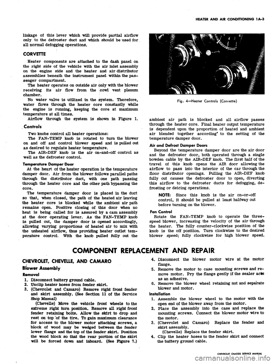
Fig.
4—Heater Controls (Corvette)
ambient air path is blocked and all airflow passes
through the heater core. Final heater output temperature
is dependent upon the proportion of heated and ambient
air blended together according* to the setting of the
temperature damper door.
Air and Defrost Damper Doors
Beyond the temperature damper door are the air door
and the defroster door, both operated through a single
bowden cable by the AIR-DEF knob. The first half of the
travel of this knob opens the AIR door allowing the
airflow to pass into the interior of the car through the
floor distributor openings. Pulling the AIR-DEF knob
fully out causes the defroster door to open, diverting
this airflow to the defroster ducts for defogging, de-
frosting or deicing operations.
NOTE: Since this knob is the air on-or-off
control, it should be pulled at least halfway out
before turning on the blower.
Fan Control
Rotate the FAN-TEMP knob to operate the three-
speed blower, increasing the velocity of the air through
the heater. The fully counter-clockwise position of the
knob is the off position. Turn clockwise to the desired
blower speed; fully clockwise for high blower speed.
COMPONENT REPLACEMENT AND REPAIR
CHEVROLET, CHEVELLE, AND CAMARO
Blower Assembly
Removal
1.
Disconnect battery ground cable.
2.
Unclip heater hoses from fender skirt.
3.
(Chevrolet and Camaro) Remove right front fender
and skirt assembly. (See Section 11 of the Service
Shop Manual)
(Chevelle) Move the vehicle front wheels to the
extreme right turn position. Remove all right front
fender retaining bolts. Allow the skirt to drop and
rest on top of the tire. To gain maximum clearance
for access to the blower motor attaching screws, a
block of wood may be wedged between the fender
lower flange and the top of the fender skirt. Position
the wood block so that the rear portion of the skirt
will be forced down and inboard. (See Figure 7.)
4.
Disconnect the blower motor wire at the motor
flange.
5.
Remove the motor to case mounting screws and re-
move motor. Pry the flange gently if the sealer acts
as an adhesive.
6. Remove the blower wheel retaining nut and separate
blower and motor.
Installation
1.
Assemble the blower wheel to the motor with the
open end of the blower away from the motor.
2.
Place the assembly into the case and replace the
mounting screws. Connect the blower motor wire to
the motor.
3.
(Chevrolet and Camaro) Replace the fender and
skirt assembly.
(Chevelle) Replace the fender skirt.
4.
Clip the heater hoses to the fender skirt and connect
the battery ground cable.
CHEVROLET CHASSIS SERVICE MANUAL
Page 27 of 659
HEATER AND AIR CONDITIONING 1A-4
CHEVROLET SHOWN AS
TYPICAL OF CHEVROLET
AND CHEVELLE
CHEVROLET
WITH CONSOLE
ONLY
THESE USED ON
CHEVROLET ONLY
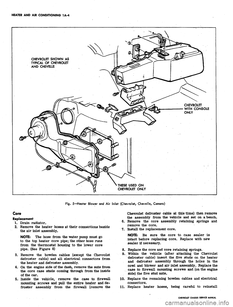
Fig. 5— Heater Blower and
Air
Inlet (Chevrolet, Chevelle, Camaro)
Core
Replacement
1.
Drain radiator.
2.
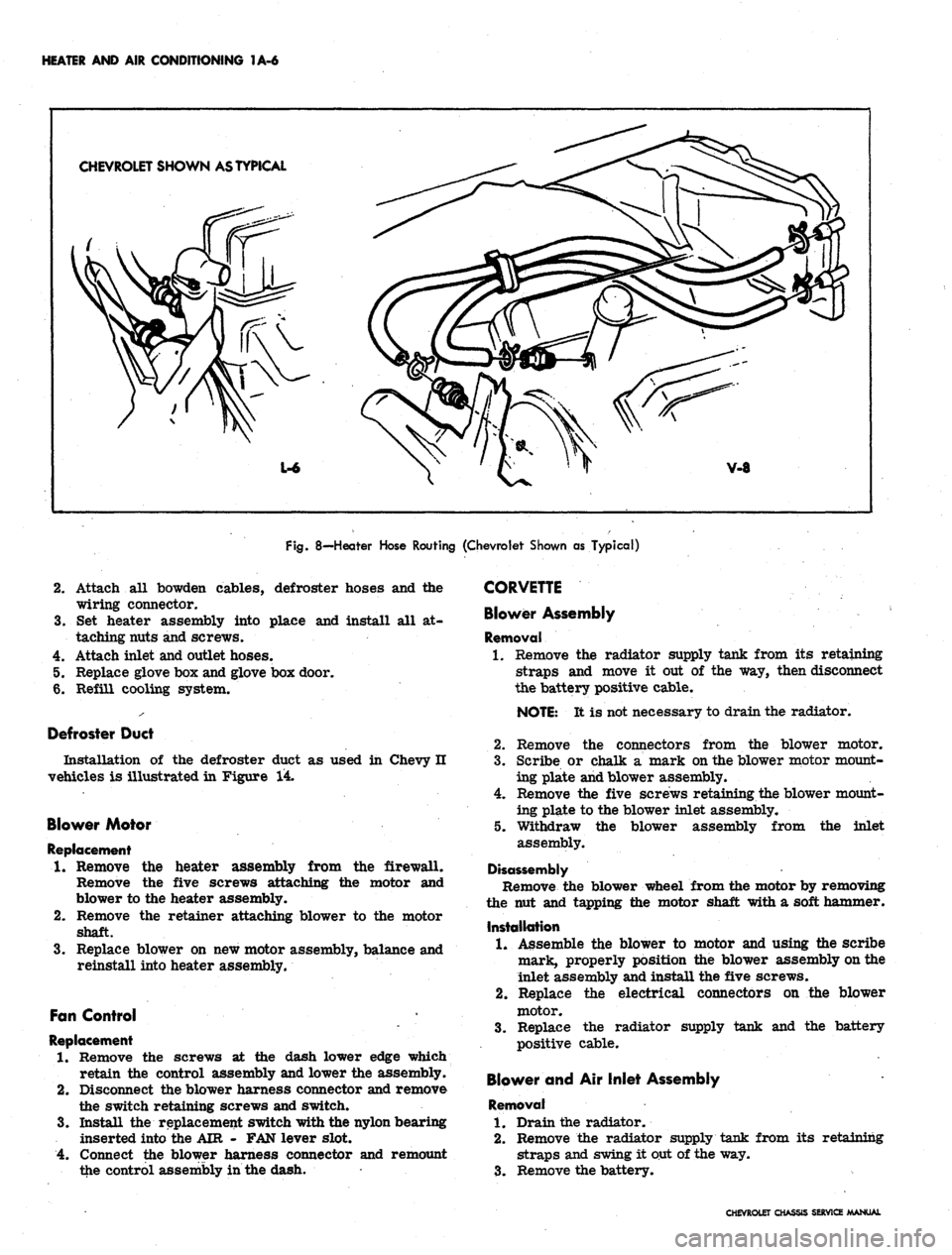
Remove the heater hoses at their connections beside
the air inlet assembly.
NOTE:
The hose from the
water,
pump
must go
to the top heater core pipe; the other hose runs
from the thermostat housing to the lower core
pipe. (See Figure 8)
3.
Remove the bowden cables (except the Chevrolet
defroster cable) and all electrical connectors from
the heater and defroster assembly.
4.
On the engine side of the dash, remove the nuts from
the core case studs coming through from the inside
of the car.
5. Inside the vehicle, remove the case to firewall
mounting screws and pull the entire heater and de-
froster assembly from the firewall (remove the
Chevrolet defroster cable at this time) then remove
the assembly from the vehicle and set on a bench.
6. Remove the core assembly retaining springs and
remove the core.
7. Install the replacement core.
NOTE:
Be sure the core to case sealer is
intact before replacing core. Replace with new
sealer if necessary.
8. Replace the core and core retaining springs.
9. Within the vehicle (after attaching the Chevrolet
defroster cable) insert the five studs on the heater
and defroster assembly through the holes in the
cowl and blower and air inlet assembly. Replace the
case to firewall mounting screws and (on the engine
side) the five stud nuts.
10.
Replace the remaining bowden cables and electrical
connectors.
11.
Replace heater hoses, being careful to reinstall
CHEVROLET CHASSIS SERVICE MANUAL
Page 28 of 659
HEATER AND AIR CONDITIONING 1A-5
them in their proper location. (See Figure 8)
12.
Refill radiator.
Defroster Duct
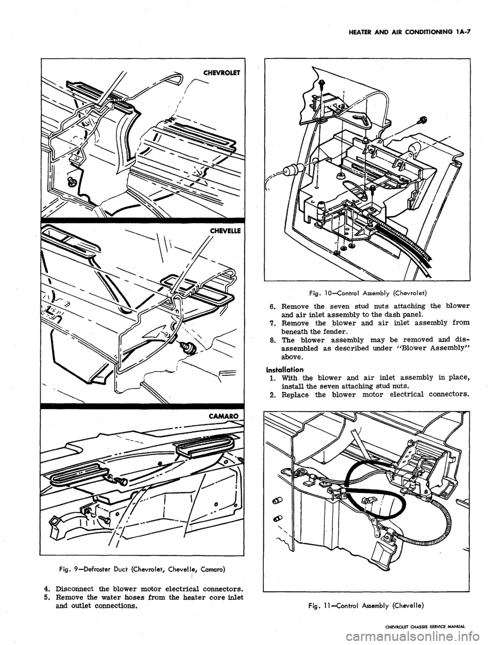
Figure 9 illustrates the defroster duct installation
on Chevrolet, Chevelle and Camaro vehicles.
Bowden Cobles
Bowden cable attachment should be made in the fol-
lowing manner:
1.
With the cables attached to the control assembly
and levers, move the levers to their fully left or
closed position.
2.
Attach cable wires to the heater valve levers and
tighten cable attaching bracket screws.
3.
Check for proper cable operation and readjust as
necessary.
Control Panel
Control panel installation is shown in Figures 10, 11,
and 12.
Fan Switch
Replacement
1.
Remove control assembly-to-instrument panel re-
inforcement attaching screws and push the control
assembly toward the front of the vehicle and down.
2.
Remove the two switch attaching screws and the
electrical connector.
3.
Replace switch, screws, and electrical connector.
4.
Place control assembly into instrument panel and
replace attaching screws.
Resistor
The resistor assembly is attached to the heater dis-
tributor assembly. It should "be replaced if low or
medium blower speed is inoperative. Remove the glove
box for access to the unit.
HEATER HOUSING
LOWER RIGHT HAND
RETAINER NUT
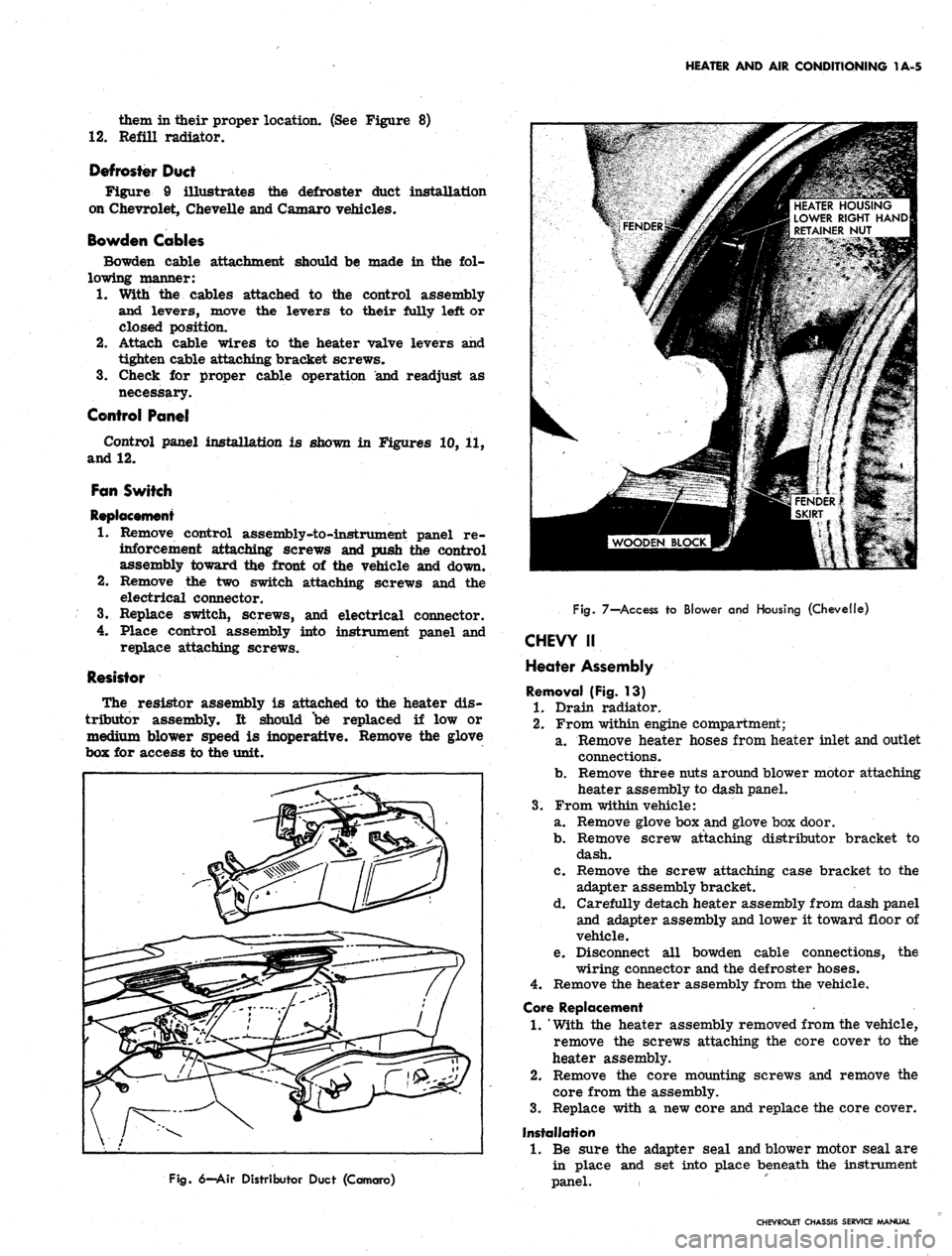
Fig.
6—Air Distributor Duct (Camaro)
Fig.
7—Access to Blower and Housing (Chevelle)
CHEVY II
Heater Assembly
Removal (Fig. 13)
1.
Drain radiator.
2.
From within engine compartment;
a. Remove heater hoses from heater inlet and outlet
connections.
b.
Remove three nuts around blower motor attaching
heater assembly to dash panel.
3.
From within vehicle:
a. Remove glove box and glove box door.
b.
Remove screw attaching distributor bracket to
dash.
c. Remove the screw attaching case bracket to the
adapter assembly bracket.
d. Carefully detach heater assembly from dash panel
and adapter assembly and lower it toward floor of
vehicle.
e. Disconnect all bowden cable connections, the
wiring connector and the defroster hoses.
4.
Remove the heater assembly from the vehicle.
Core Replacement
1.
'With the heater assembly removed from the vehicle,
remove the screws attaching the core cover to the
heater assembly.
2.
Remove the core mounting screws and remove the
core from the assembly.
3.
Replace with a new core and replace the core cover.
Installation
1.
Be sure the adapter seal and blower motor seal are
in place and set into place beneath the instrument
panel.
CHEVROLET CHASSIS SERVICE MANUAL
Page 29 of 659
HEATER AND AIR CONDITIONING 1A-6
CHEVROLET SHOWN AS TYPICAL
Fig.
8—Heater Hose Routing (Chevrolet Shown as Typical)
cables, defroster hoses and the
place and install all at-
4.
5.
6.
Attach all bowden
wiring connector.
Set heater assembly into
taching nuts and screws.
Attach inlet and outlet hoses.
Replace glove box and glove box door.
Refill cooling system.
Defroster Duct
Installation of the defroster duct as used in Chevy H
vehicles is illustrated in Figure 14.
Blower Motor
Replacement
1.
Remove the heater assembly from the firewall.
Remove the five screws attaching the motor and
blower to the heater assembly.
2.
Remove the retainer attaching blower to the motor
shaft.
3.
Replace blower on new motor assembly, balance and
reinstall into heater assembly.
Fan Control
Replacement
1.
Remove the screws at the dash lower edge which
retain the control assembly and lower the assembly.
2.
Disconnect the blower harness connector and remove
the switch retaining screws and switch.
3.
Install the replacement switch with the nylon bearing
inserted into the AIR - FAN lever slot.
4.
Connect the blower harness connector and remount
the control assembly in the dash.
CORVETTE
Blower Assembly
Removal
1.
Remove the radiator supply tank from its retaining
straps and move it out of the way, then disconnect
the battery positive cable.
NOTE:
It is not necessary to drain the radiator.
2.
Remove the connectors from the blower motor.
3.
Scribe or chalk a mark on the blower motor mount-
ing plate and blower assembly.
4.
Remove the five screws retaining the blower mount-
ing plate to the blower inlet assembly.
Withdraw the blower assembly from the inlet
5.
assembly.
Disassembly
Remove the blower wheel from the motor by removing
the nut and tapping the motor shaft with a soft hammer.
Installation
1.
Assemble the blower to motor and using the scribe
mark, properly position the blower assembly on the
inlet assembly and install the five screws.
2.
Replace the electrical connectors on the blower
motor.
3.
Replace the radiator supply tank and the battery
positive cable.
Blower and Air Inlet Assembly
Removal
1.
Drain the radiator.
2.
Remove the radiator supply tank from its retaining
straps and swing it out of the way.
3.
Remove the battery.
CHEVROLET CHASSIS SERVICE MANUAL
Page 30 of 659
HEATER AND AIR CONDITIONING 1A-7
Fig.
10—Control Assembly (Chevrolet)
6. Remove the seven stud nuts attaching the blower
and air inlet assembly to the dash panel.
7.
Remove the blower and air inlet assembly from
beneath the fender.
8. The blower assembly may be removed and dis-
assembled as described under "Blower Assembly"
above.
Installation
1.
With the blower and air inlet assembly in place,
install the seven attaching stud nuts.
2.
Replace the blower motor electrical connectors.
Fig.
9—Defroster Duct (Chevrolet, Chevell^, Camaro)
4.
Disconnect the blower motor electrical connectors.
5.
Remove the water hoses from the heater core inlet
and outlet connections.
\
N
^
1
Fig.
11-Controi Assembly (Chevelle)
CHEVROLET CHASSIS SERVICE MANUAL