Engine wiring CHEVROLET CAMARO 1967 1.G Chassis Owner's Manual
[x] Cancel search | Manufacturer: CHEVROLET, Model Year: 1967, Model line: CAMARO, Model: CHEVROLET CAMARO 1967 1.GPages: 659, PDF Size: 114.24 MB
Page 341 of 659
ENGINE-ELECTRICAL
6Y-16
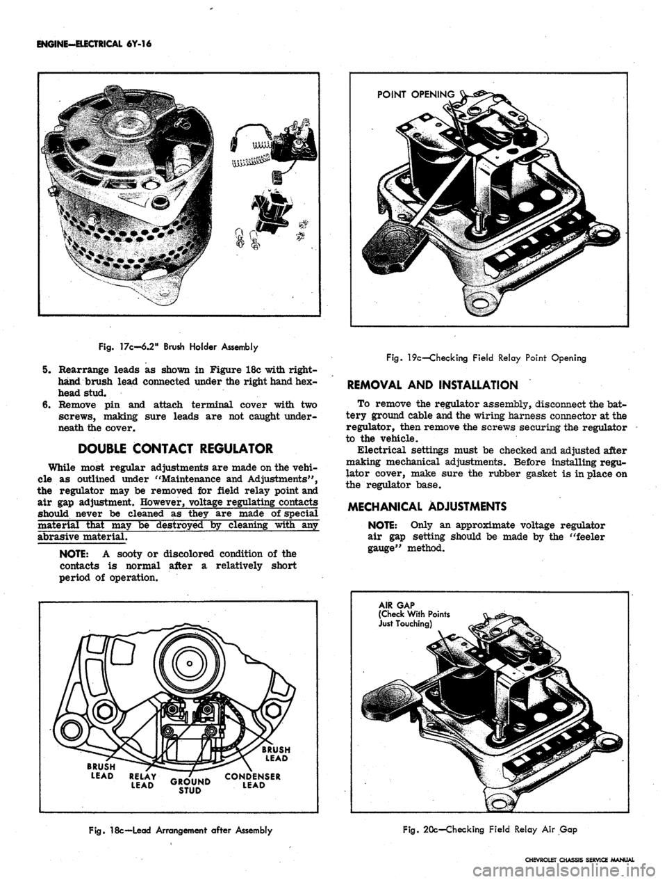
POINT
OPENINGJL
Fig. 17c-6.2"
Brush
Holder
Assembly
5. Rearrange leads as shown in Figure 18c with right-
hand brush lead connected under the right hand hex-
head stud.
6. Remove pin and attach terminal cover with two
screws, making sure leads are not caught under-
neath the cover.
DOUBLE CONTACT REGULATOR
While most regular adjustments are made on the vehi-
cle as outlined under "Maintenance and Adjustments",
the regulator may be removed for field relay point and
air gap adjustment. However, voltage regulating contacts
should never be cleaned as they are made of special
material that may be destroyed by cleaning with any
abrasive material.
NOTE:
A sooty or discolored condition of the
contacts is normal after a relatively short
period of operation.
Fig. 19c—Checking Field Relay Point Opening
REMOVAL AND INSTALLATION
To remove the regulator assembly, disconnect the bat-
tery ground cable and the wiring harness connector at the
regulator, then remove the screws securing the regulator
to the vehicle.
Electrical settings must be checked and adjusted after
making mechanical adjustments. Before installing regu-
lator cover, make sure the rubber gasket is in place on
the regulator base.
MECHANICAL ADJUSTMENTS
NOTE:
Only an approximate voltage regulator
air gap setting should be made by the "feeler
gauge" method.
BRUSH
LEAD
BRUSH
LEAD
RELAY
^B-/lliLlK
CONDENSER
LEAD
GROUND
LEAD
STUD
AIR GAP
(Check
With
Points
Just
Touching)
Fig.
18c—Lead
Arrangement
after
Assembly
Fig. 20c—Checking Field Relay Air Gap
CHEVROLET CHASSIS SERVICE MANUAL
Page 344 of 659
MAINTENANCE AND ADJUSTMENTS
ENGINE-ELECTRICAL 6Y-19
PERIODIC MAINTENANCE
BREAKER POINT SYSTEM
The distributor breaker points and spark plugs are the
only ignition system components that require periodic
service. The remainder of the ignition system requires
only periodic inspection to check operation of the units,
tightness of the electrical connections, and condition of
the wiring. When checking the coil, test with a reputable
tester.
Breaker type distributors are equipped with cam lubri-
cator and should have the wick replaced at the same time
contact point set is replaced. It is not necessary to
lubricate the breaker cam when using a cam lubricator.
Do not attempt to lubricate the wick - Replace when
necessary. When installing a new wick, adjust its posi-
tion so the end of the wick just touches the lobe of the
breaker cam.
Distributor shaft lubrication is accomplished by a
reservoir of lube around the mainshaft in the distributor
body.
BREAKERLESS SYSTEM
Since there are no moving parts in the ignition pulse
amplifier unit mounted forward of the radiator bulkhead,
and the distributor shaft and bushings have permanent
type lubrication, no periodic maintenance is therefore
required for the breakerless ignition system. The dis-
tributor lower bushing is lubricated by engine oil through
a splash hole in the distributor housing, and a housing
cavity next to the upper bushing contains a supply of
lubricant which will last between overhaul periods. At
time of overhaul, the upper bushing may be lubricated
by removing the plastic seal and then adding SAE 20 oil
to the packing in the cavity. A new plastic seal will be
required since the old one will be damaged during
removal.
Tachometer readings for test purposes can be made on
the primary circuit of the breakerless ignition system in
the same manner as on the conventional ignition system,
however before attempting to connect a test tachometer
into the primary circuit check with your instrument
supplier to insure that satisfactory readings can be
obtained and the breakerless system will not be damaged
by the tachometer that is to be used,
IGNITION COIL CHECK (BREAKERLESS)
The ignition coil primary can be checked for an open
PULSE
AMPLIFIER
IGN. SWITCH WIRE
"("IGN" TERMINAL)
-E3 IJU
12
WHITE-
-20 BLACKf' • 12 WHITE-
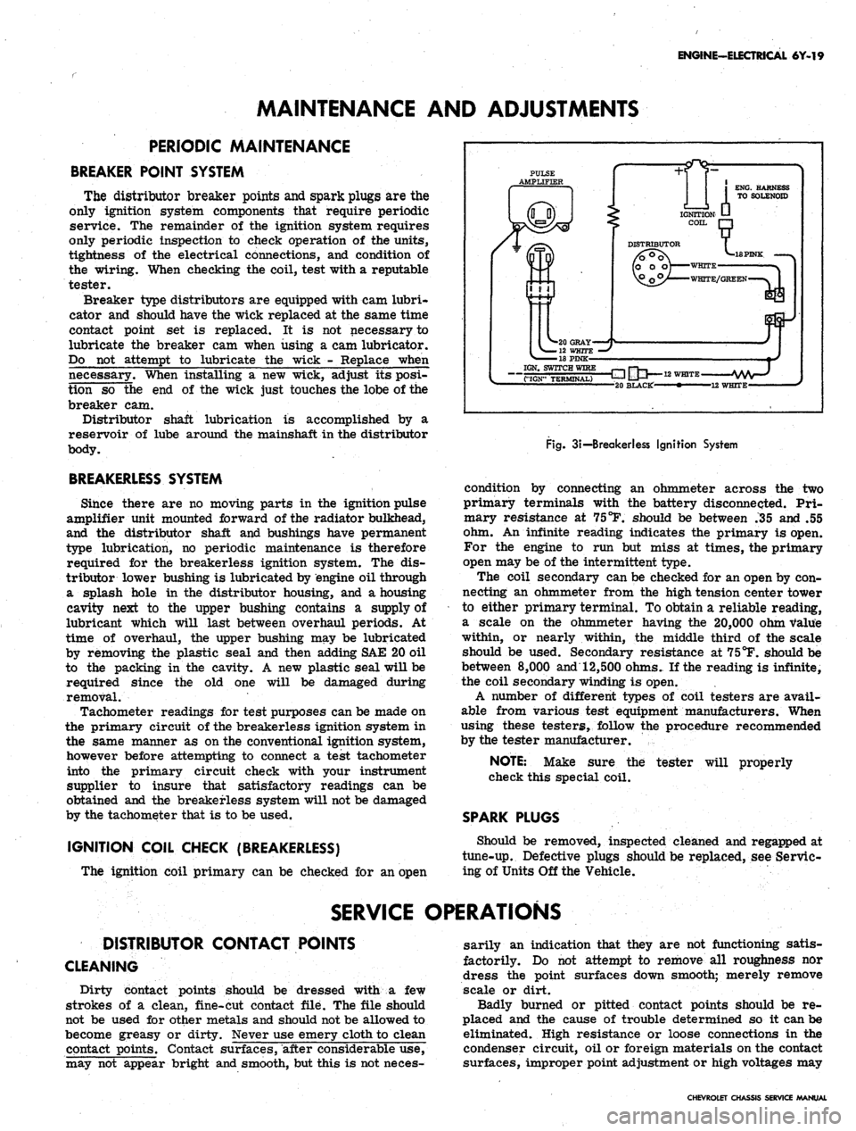
Fig.
3i—
Breakerless Ignition System
condition by connecting an ohmmeter across the two
primary terminals with the battery disconnected. Pri-
mary resistance at 75
°F.
should be between .35 and .55
ohm. An infinite reading indicates the primary is open.
For the engine to run but miss at times, the primary
open may be of the intermittent type.
The coil secondary can be checked for an open by con-
necting an ohmmeter from the high tension center tower
to either primary terminal. To obtain a reliable reading,
a scale on the ohmmeter having the 20,000 ohm value
within, or nearly within, the middle third of the scale
should be used. Secondary resistance at 75°F. should be
between
8,000
and 12,500 ohms. If the reading is infinite,
the coil secondary winding is open.
A number of different types of coil testers are avail-
able from various test equipment manufacturers. When
using these testers, follow the procedure recommended
by the tester manufacturer.
tester will properly
NOTE:
Make sure the
check this special coil.
SPARK PLUGS
Should be removed, inspected cleaned and regapped at
tune-up. Defective plugs should be replaced, see Servic-
ing of Units Off the Vehicle.
SERVICE OPERATIONS
DISTRIBUTOR CONTACT POINTS
CLEANING
Dirty contact points should be dressed with a few
strokes of a clean, fine-cut contact file. The file should
not be used for other metals and should not be allowed to
become greasy or dirty. Never use emery cloth to clean
contact points. Contact surfaces, after considerable use,
may not appear bright and smooth, but this is not neces-
sarily an indication that they are not functioning satis-
factorily. Do not attempt to remove all roughness nor
dress the point surfaces down smooth; merely remove
scale or dirt.
Badly burned or pitted contact points should be re-
placed and the cause of trouble determined so it can be
eliminated. High resistance or loose connections in the
condenser circuit, oil or foreign materials on the contact
surfaces, improper point adjustment or high voltages may
CHEVROLET CHASSIS SERVICE MANUAL
Page 354 of 659
ENGINE-ELECTRICAL 6Y-29
each capacitor (not illustrated). The capacitor is
shorted if both readings are zero.
6. Resistor Rl: The resistor is open if both readings
are infinite.
7. Resistor R2: Use an ohmmeter scale on which the
1800 ohm value is within, or nearly within, the
middle third of the scale. If both readings are infi-
nite, the resistor is open.
8. Resistor R3: Use an ohmmeter scale on which the
680 Ohm value is within, or nearly within, the middle
third of the scale. If both readings are infinite, the
resistor is open.
9. Resistor R4: Select an ohmmeter scale on which the
15000 ohm value is within, or nearly .within, the
middle third of the scale. If either reading is infi-
nite, the resistor is open. ~
10.
Resistor R5: Use the lowest range ohmmeter scale.
The resistor is open if either reading is infinite.
NOTE:
This resistor on some applications may
be located in the vehicle wiring harness, and not
on the panel board.
11.
Resistor R6: An ohmmeter scale on which the 150
ohm value is within or nearly within, the middle
third of the scale should be used. If both readings
are infinite, the resistor is open.
REASSEMBLY
During assembly, coat with silicone grease both sides
of the flat insulators used between the transistors and
heat sink, and also the heat sink on the side on which the
transistors are mounted. The silicone grease, which is
available commercially, conducts heat and thereby pro-
vides better cooling.'
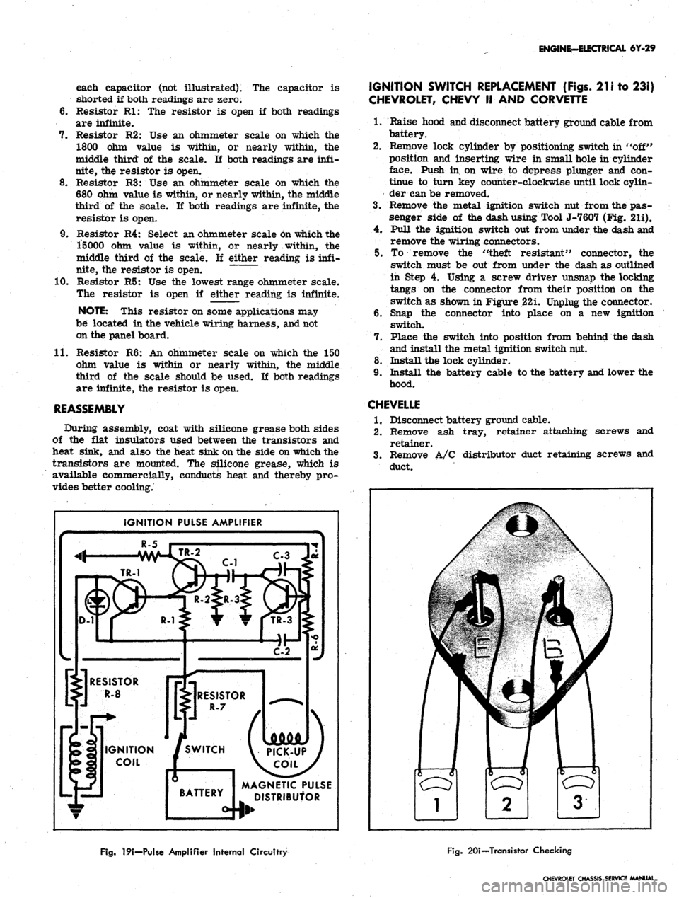
IGNITION PULSE AMPLIFIER
R-5
C-3 Ju
MAGNETIC PULSE
DISTRIBUTOR
IGNITION SWITCH REPLACEMENT (Figs.
21
i to 23i)
CHEVROLET, CHEVY II AND CORVETTE
1.
Raise hood and disconnect battery ground cable from
battery.
2.
Remove lock cylinder by positioning switch in "off"
position and inserting wire in small hole in cylinder
face. Push in on wire to depress plunger and con-
tinue to turn key counter-clockwise until lock cylin-
der can be removed.
3.
Remove the metal ignition switch nut from the pas-
senger side of the dash using Tool J-7607 (Fig. 21i).
4.
Pull the ignition switch out from under the dash and
remove the wiring connectors.
5. To remove the "theft resistant" connector, the
switch must be out from under the dash as outlined
in Step 4. Using a screw driver unsnap the locking
tangs on the connector from their position on the
switch as shown in Figure 22i. Unplug the connector.
6. Snap the connector into place on a new ignition
switch.
7. Place the switch into position from behind the dash
and install the metal ignition switch nut.
8. Install the lock cylinder.
9. Install the battery cable to the battery and lower the
hood.
CHEVELLE
1.
Disconnect battery ground cable.
2.
Remove ash tray, retainer attaching screws and
retainer.
3.
Remove A/C distributor duct retaining screws and
duct.
Fig.
19i—Pulse Amplifier Internal Circuitry
Fig.
20i—Transistor Checking
CHEVROLET Oi
Page 355 of 659

ENGINE-ELECTRICAL-6Y-30
Fig.
2 li—Removing Ignition Switch Nut
4.
Remove heater and/or A/C control panel assembly
retaining screws and push panel assembly from
console.
NOTE: If interference between control panel
and radio is encountered, loosen radio retaining
nuts.
5.
Remove radio control knobs, bezels and retaining
nuts.
6. Disconnect radio wiring harness and antenna lead-in.
7.
Remove radio rear brace attaching screw and re-
move radio from vehicle.
Fig.
231—Switch and Connector Unplugged
8. Remove ignition switch bezel nut using Tool J-7607
and push switch rearward from panel opening.
9. Disconnect wiring connector from rear of switch.
10.
To install, reverse removal procedure.
SPARK PLUGS
CLEANING AND REGAPPING
Clean the spark plugs thoroughly, using an abrasive-
type cleaner. If the porcelains are badly glazed or
blistered, the spark plugs should be replaced. All spark
plugs must be of the same make and number or heat
range. Use a round feeler gauge to adjust the spark plug
gap to specifications (fig. 24i).
Fig.
22i—Unlocking Ignition Switch Connector
Fig.
241—Setting Sfxirk Plug Gap
CHEVROLET CHASSIS SERVICE MANUAL
Page 357 of 659
ENGINE-ELECTRICAL 6Y-32
STARTER CIRCUIT
INDEX
Page
General Description 6Y-32
Maintenance and Adjustments . '. . 6Y-32
Resistance Checks 6Y-32
Starting Motor and Solenoid Check 6Y-33
Page
Service Operations 6Y-33
Starter Motor 6Y-33
Removal and Installation 6Y-33
GENERAL DESCRIPTION
The function of the starting system, composed of the
starting motor, solenoid and battery, is to crank the
engine. The battery supplies the electrical energy, the
solenoid completes the circuit to the starting motor, and
the motor then does the actual work of cranking the
engine.
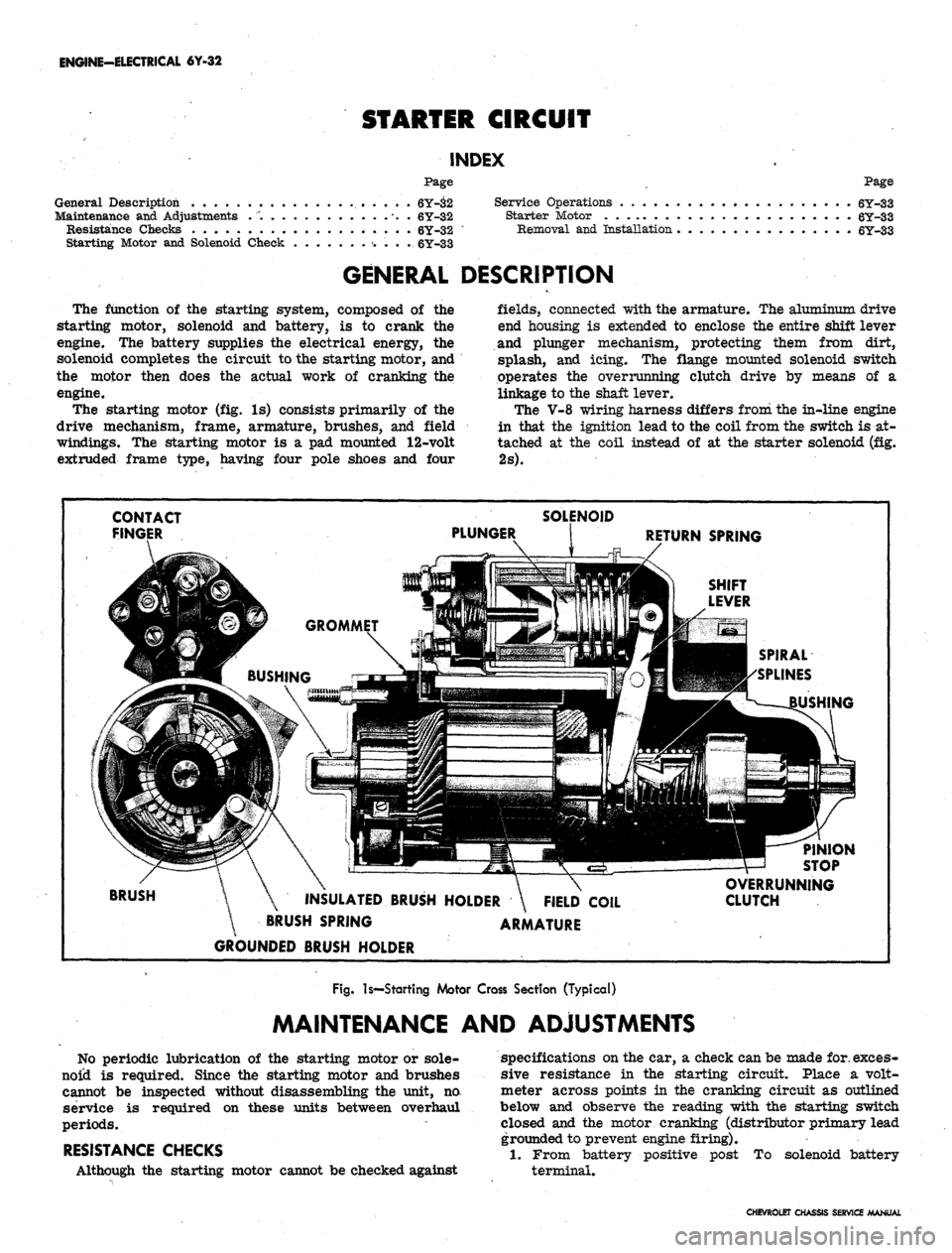
The starting motor (fig. Is) consists primarily of the
drive mechanism, frame, armature, brushes, and field
windings. The starting motor is a pad mounted 12-volt
extruded frame type, having four pole shoes and four
fields,
connected with the armature. The aluminum drive
end housing is extended to enclose the entire shift lever
and plunger mechanism, protecting them from dirt,
splash, and icing. The flange mounted solenoid switch
operates the overrunning clutch drive by means of a
linkage to the shaft lever.
The V-8 wiring harness differs from the in-line engine
in that the ignition lead to the coil from the switch is at-
tached at the coil instead of at the starter solenoid (fig.
2s).
CONTACT
FINGER
PINION
STOP
BRUSH
INSULATED BRUSH HOLDER \ FIELD COIL
BRUSH SPRING ARMATURE
GROUNDED BRUSH HOLDER
OVERRUNNING
CLUTCH
Fig.
Is—Starting Motor Cross Section (Typical)
MAINTENANCE AND ADJUSTMENTS
No periodic lubrication of the starting motor or sole-
noid is required. Since the starting motor and brushes
cannot be inspected without disassembling the unit, no.
service is required on these units between overhaul
periods.
RESISTANCE CHECKS
Although the starting motor cannot be checked against
specifications on the car, a check can be made for. exces-
sive resistance in the starting circuit. Place a volt-
meter across points in the cranking circuit as outlined
below and observe the reading with the starting switch
closed and the motor cranking (distributor primary lead
grounded to prevent engine firing).
1.
From battery positive post To solenoid battery
terminal.
CHEVROLET CHASSIS SERVICE MANUAL
Page 372 of 659
CLUTCH AND TRANSMISSIONS 7-13
PULL-IN
WINDING
li
HOLD-IN
WINDING
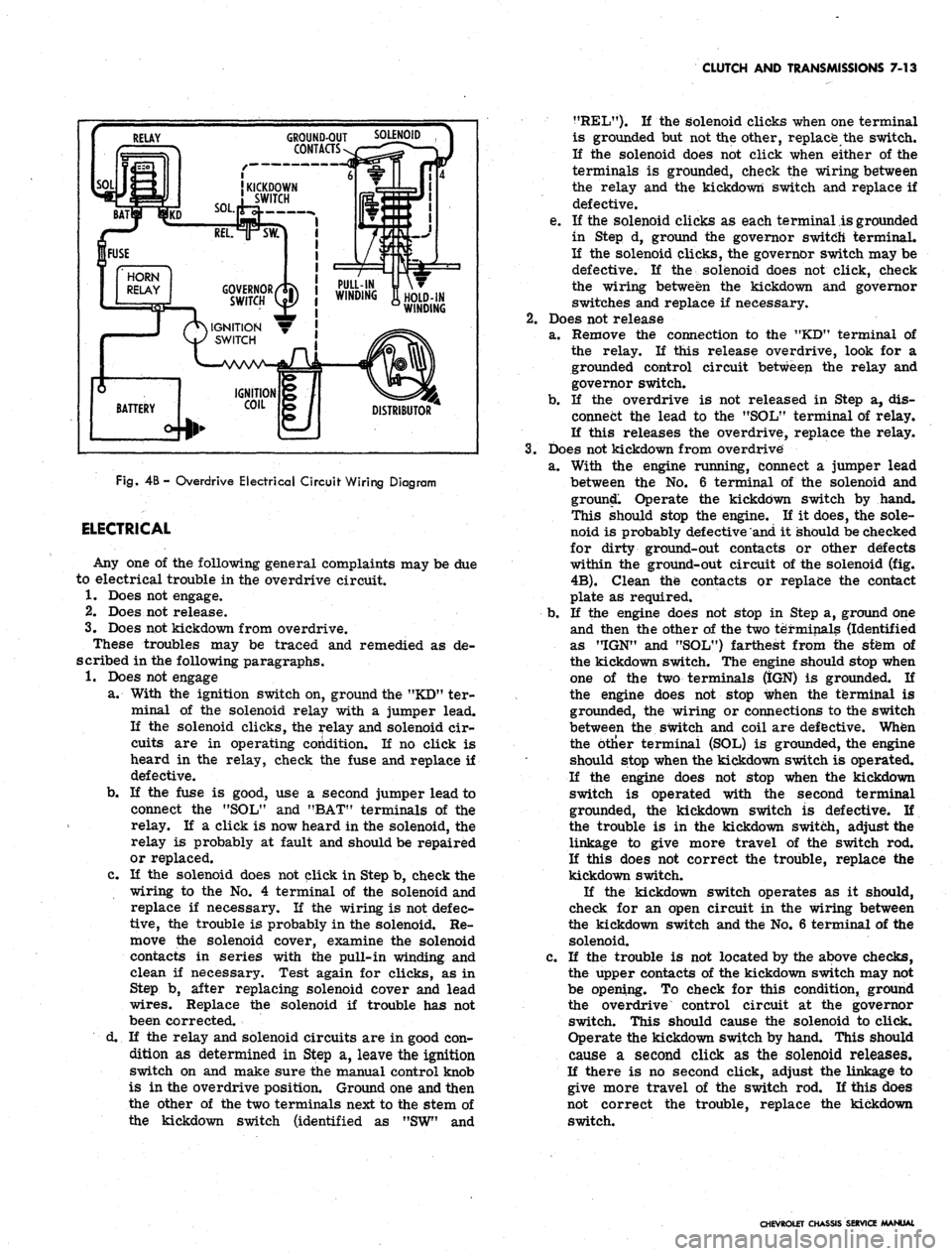
Fig.
4B -
Overdrive Electrical Circuit Wiring Diagram
ELECTRICAL
Any one of the following general complaints may be due
to electrical trouble in the overdrive circuit.
1.
Does not engage.
2.
Does not release.
3.
Does not kickdown from overdrive.
These troubles may be traced and remedied as de-
scribed in the following paragraphs.
1.
Does not engage
a. With the ignition switch on, ground the "KD" ter-
minal of the solenoid relay with a jumper lead.
If the solenoid clicks, the relay and solenoid cir-
cuits are in operating condition. If no click is
heard in the relay, check the fuse and replace if
defective.
b.
If the fuse is good, use a second jumper lead to
connect the "SOL" and "BAT" terminals of the
relay. If a click is now heard in the solenoid, the
relay is probably at fault and should be repaired
or replaced.
c. If the solenoid does not click in Step b, check the
wiring to the No. 4 terminal of the solenoid and
replace if necessary. If the wiring is not defec-
tive,
the trouble is probably in the solenoid. Re-
move the solenoid cover, examine the solenoid
contacts in series with the pull-in winding and
clean if necessary. Test again for clicks, as in
Step b, after replacing solenoid cover and lead
wires.
Replace the solenoid if trouble has not
been corrected.
d. If the relay and solenoid circuits are in good con-
dition as determined in Step a, leave the ignition
switch on and make sure the manual control knob
is in the overdrive position. Ground one and then
the other of the two terminals next to the stem of
the kickdown switch (identified as "SW" and
?fREL"). K the solenoid clicks when one terminal
is grounded but not the other, replace the switch.
If the solenoid does not click when either of the
terminals is grounded, check the wiring between
the relay and the kickdown switch and replace if
defective.
e. If the solenoid clicks as each terminal is grounded
in Step d, ground the governor switch terminal.
If the solenoid clicks, the governor switch may be
defective. If the solenoid does not click, check
the wiring between the kickdown and governor
switches and replace if necessary.
2.
Does not release
a. Remove the connection to the "KD" terminal of
the relay. If this release overdrive, look for a
grounded control circuit between the relay and
governor switch.
b.
If the overdrive is not released in Step a, dis-
connect the lead to the "SOL" terminal of relay.
If this releases the overdrive, replace the relay.
3.
Does not kickdown from overdrive
a. With the engine running, connect a jumper lead
between the No. 6 terminal of the solenoid and
ground. Operate the kickdown switch by hand.
This should stop the engine. If it does, the sole-
noid is probably defective and it should be checked
for dirty ground-out contacts or other defects
within the ground-out circuit of the solenoid (fig.
4B).
Clean the contacts or replace the contact
plate as required.
b.
If the engine does not stop in Step a, ground one
and then the other of the two terminals (Identified
as "IGN" and "SOL") farthest from the sfem of
the kickdown switch. The engine should stop when
one of the two terminals (IGN) is grounded. If
the engine does not stop when the terminal is
grounded, the wiring or connections to the switch
between the switch and coil are defective. When
the btlier terminal (SOL) is grounded, the engine
should stop when the kickdown switch is operated.
If the engine does not stop when the kickdown
switch is operated with the second terminal
grounded, the kickdown switch is defective. If
the trouble is in the kickdown switch, adjust the
linkage to give more travel of the switch rod.
If this does not correct the trouble, replace the
kickdown switch.
If the kickdown switch operates as it should,
check for an open circuit in the wiring between
the kickdown switch and the No. 6 terminal of the
solenoid.
c. If the trouble is not located by the above checks,
the upper contacts of the kickdown switch may not
be opening. To check for this condition, ground
the overdrive control circuit at the governor
switch. This should cause the solenoid to click.
Operate the kickdown switch by hand. This should
cause a second click as the solenoid releases.
If there is no second click, adjust the linkage to
give more travel of the switch rod. If this does
not correct the trouble, replace the kickdown
switch.
CHEVROLET CHASSIS SERVICE MANUAL
Page 452 of 659
STEERING 9-12
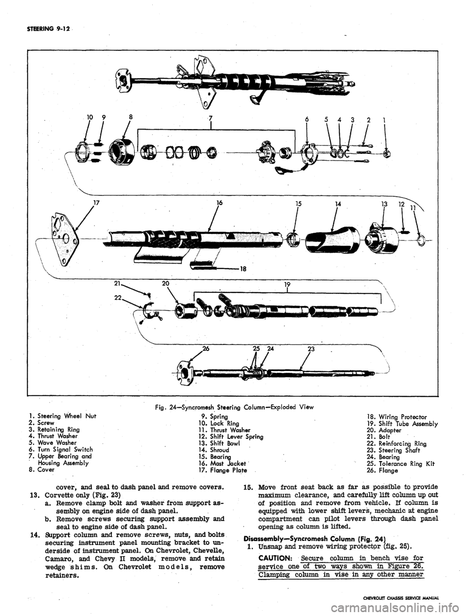
1.
Steering Wheel Nut
2i Screw
3. Retaining Ring
4.
Thrust Washer
5. Wave Washer
6. Turn Signal Switch
7. Upper Bearing and
Housing Assembly
8. Cover
Fig.
24—Syncromesh Steering Column—Exploded View
9. Spring
1.0. Lock Ring
11.
Thrust Washer
12.
Shift Lever Spring
13.
Shift Bowl
14.
Shroud
15.
Bearing
16.
Mast Jacket
17.
Flange Plate
18.
Wiring Protector
19.
Shift Tube Assembly
20.
Adapter
21.
Bolt
22.
Reinforcing Ring
23.
Steering Shaft
24.
Bearing
25.
Tolerance Ring Kit
26.
Flange
cover, and seal to dash panel and remove covers.
13.
Corvette only (Fig. 23)
a. Remove clamp bolt and washer from support as-
sembly on engine side of dash panel.
b.
Remove screws securing support assembly and
seal to engine side of dash panel.
14.
Support column and remove screws, nuts, and bolts
securing instrument panel mounting bracket to un-
derside of instrument panel. On Chevrolet, Chevelle,
Camaro, and Chevy II models, remove and retain
wedge shims. On Chevrolet models, remove
retainers.
15.
Move front seat back as far as possible to provide
maximum clearance, and carefully lift column up out
of position and remove from vehicle. If column is
equipped with lower shift levers, mechanic at engine
compartment can pilot levers through dash panel
opening as column is lifted.
Disassembly'—Syncromesh Column (Fig. 24)
1.
Unsnap and remove wiring protector (fig. 25).
CAUTION: Secure column in bench vise for
service one of two ways shown in Figure 26.
Clamping column in vise in any other manner
CHEVROLET CHASSIS SERVICE MANUAL
Page 469 of 659

STEERING 9-29
column mounting bracket, and place bracket in cor-
rect position on underside of instrument panel.
Loosely install bracket using bracket to column
mounting screws and bracket to instrument panel
washers and bolts.
NOTE: Steering shaft to gear clamp must be
tightened before column attaching bolts are
torqued. Refer to "Steering Gear-Chevy n",
installation procedure, for correct Chevy II
steering column alignment procedure.
5.
Camaro only (fig. 60):
Lay wedge shim in position on instrument panel
column mounting bracket and place bracket in cor-
rect position on underside of instrument panel.
Loosely install bracket using bracket to column
mounting screws, nuts, and washer and bolt as shown
in Figure 60.
6. Corvette only (fig. 61):
Loosely secure column mounting bracket to sup-
port plate and instrument panel with washers and
bolts.
7.
Secure flanged end of column to steering coupling
with lockwashers and nuts. On Chevy n, connect col-
umn to steering gear with clamp, clamp bolt, and
nut. On Corvette, slide steering shaft flange into
lower coupling
half,
and install upper clamp bolt
loosely; also secure support, seal and clamp loosely
at dash on engine side.
8. Tighten instrument panel mounting bracket bolts and
nuts.
Refer to torque specifications at rear of manual
for correct torque values.
9. Chevrolet only (fig. 15):
Place upper and lower mast jacket covers in po-
sition and secure covers together and to instrument
panel using nuts and screws as shown in Figure 15.
10.
Chevy H only (fig. 18):
Place lower mast jacket cover in position under
mast jacket and secure to upper cover with screws.
11.
CheveUe only (fig. 15):
Place mast jacket trim cover in position over col-
Fig.
61—Instrument Panel Mounting Bracket and
Support Plqte—Corvette
umn on underside of instrument panel and secure
with screws.
12.
Corvette only (fig. 14):
Slide escutcheon into position at instrument panel
and secure with screws. Place upper end lower
covers in position and secure with screws.
13.
On Chevrolet and CheveUe models with column
mounted powerglide controls, secure transmission
shift indicator pointer into position with set screw
(fig. 15). ,
14.
Chevrolet only (fig. 19):
a. Secure seal and cover to dash panel with screws.
b.
Place clamp assembly in position and install
clamp screw.
c. Install dash panel trim cover with mounting
screws.
15.
Chevelle only (fig. 20):
a. Secure seal and inner and outer covers to dash
panel with screws.
b.
Secure inner and outer covers together with
screws.
c. Install trim cover to dash panel with two
retainers.
16.
Chevy H only (fig. 21):
a. Secure seal, retainer, and clamp to dash panel
with screws.
b.
Install clamp screw.
c. Slide collar into position. Pinch and staple upper
tabs together.
17.
Camaro only (fig. 22):
a. Secure seal, upper cover, and lower cover to
dash panel with screws.
b.
Secure upper and lower cover together with
screws.
c. Fold rubber boot over securely against dash panel
to conceal covers.
18.
Corvette only (fig. 23):
a. Secure seal and support assembly to dash panel
on engine compartment side.
b.
Tighten clamp, washer, and clamp bolt on engine
compartment side.
19.
Connect transmission linkage to lower shift tube
levers in engine compartment, if column is so
equipped. Adjust levers as outlined in Section 7.
20.
Install steering wheel as outlined in this section.
21.
Connect directional signal, horn, back-up lamp, and
neutral start switch at wiring harness plugs. Adjust
back-up lamp, neutral start switch as outlined in
Section 12.
22.
Adjust steering gear and align and center steering
wheel as outlined in this section.
STEERING LINKAGE (Fig. 62)
TIE RODS
There are two tie rod assemblies used on all models.
Each assembly is of three piece construction, consisting
of a sleeve and two tie rod ends. The ends are threaded
into the sleeve and locked with clamps. Right and left
hand threads are provided to facilitate toe-in adjustment
and steering gear centering.
The tie rod ends are self-adjusting for wear and re-
quire no attention in service other than periodic lubrica-
tion and occasional inspection to see that ball studs are
tight. Replacement of tie rod ends should be made when
CHEVROLET CHASSIS SERVICE MANUAL
Page 474 of 659
STEERING 9-34
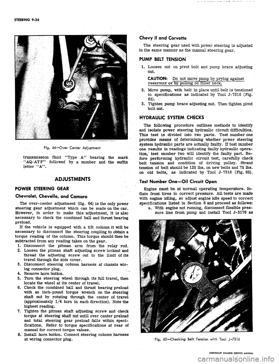
Fig.
64-Over Center Adjustment
transmission fluid "Type A" bearing the mark
"AQ-ATF" followed by a number and the suffix
letter "A".
ADJUSTMENTS
POWER STEERING GEAR
Chevrolet, Chevelle, and Camaro
The over-center adjustment (fig. 64) is the only power
steering gear adjustment which can be made on the car.
However, in order to make this adjustment, it is also
necessary to check the combined ball and thrust bearing
preload.
If the vehicle is equipped with a tilt column it will be
necessary to disconnect the steering coupling to obtain a
torque reading of the column. This torque should then be
subtracted from any reading taken on the gear.
1.
Disconnect the pitman arm from the relay rod.
2.
Loosen the pitman shaft adjusting screw loeknut and
thread the adjusting screw out to the limit of its
travel through the side cover. '. •
3.
Disconnect steering column harness at chassis wir-
ing connector plug.
4.
Remove horn button.
5.
Turn the steering wheel through its full travel, then
locate the wheel at its center of travel.
6. Gheck the combined ball and thrust bearing preload
with an inch-pound torque wrench on the steering
shaft nut by rotating through the center of travel
(approximately 1/4 turn in each direction). Note the
highest reading.
7.
Tighten the pitman shaft adjusting screw and check
torque at steering shaft nut until over center preload
and total steering gear preload falls within speci-
fications. Refer to torque specifications at rear of
manual for correct torque values.
8. Install horn button. Connect steering column harness
at wiring connector plug.
Chevy II and Corvette
The steering gear used with power steering is adjusted
in the same manner as the manual steering gear.
PUMP BELT TENSION
1.
Loosen nut on pivot bolt and pump brace adjusting
nut.
CAUTION: Do not move pump by prying against
reservoir or by pulling on filler neck.
2.
Move pump, with belt in place until belt is tensioned
to specifications as indicated by Tool J-7316 (Fig-.
65).
3.
Tighten pump brace adjusting nut. Then tighten pivot
bolt nut.
HYDRAULIC SYSTEM CHECKS
The following procedure outlines methods to identify
and isolate power steering hydraulic circuit difficulties.
This test is divided into two parts. Test number one
provides means of determining whether power steering
system hydraulic parts are actually faulty. If test number
one results in readings indicating faulty hydraulic opera-
tion, test number two will identify the faulty part. Be-
fore performing hydraulic circuit test, carefully check
belt tension and condition of driving pulley. Strand
tension of belt should be 125 lbs. on new belts and 75 lbs.
on old belts, as indicated by Tool J-7316 (Fig. 65).
Test Number One—Oil Circuit Open
Engine must be at normal operating temperature. In-
flate front, tires to correct pressure. All tests are made
with engine idling, so adjust engine idle speed to correct
specifications listed in Section 6 and proceed as follows:
a. With engine not running, disconnect flexible pres-
sure line from pump and install Tool J-5176 as
Fig.
65— Checking Belt Tension with Tool J-7316
CHEVROLET CHASSIS SERVICE MANUAL
Page 514 of 659
ELECTRICAL-BODY AND CHASSIS 12-2
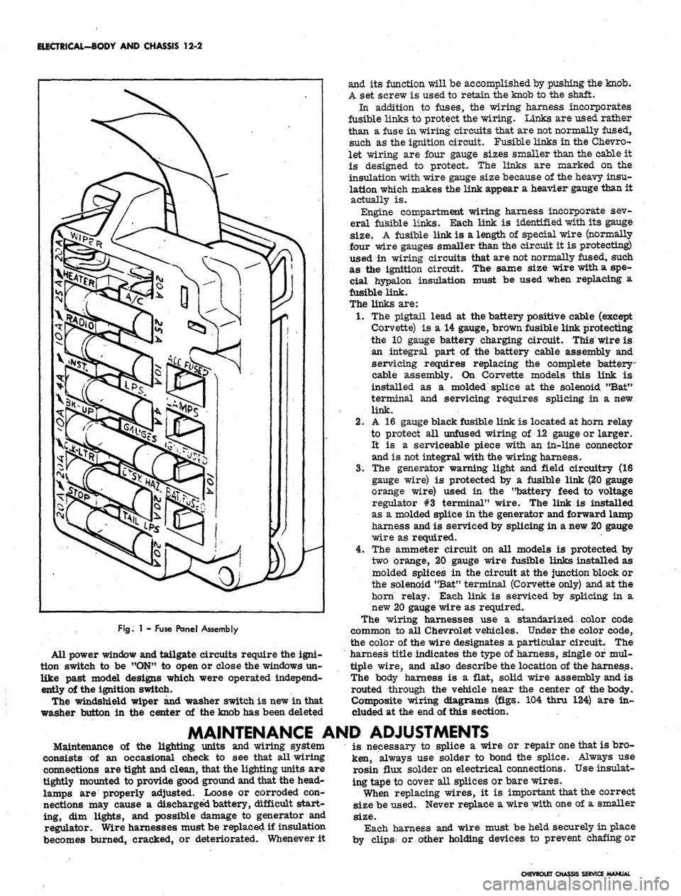
FJg.
1 - Fuse Panel Assembly
All power window and tailgate circuits require the igni-
tion switch to be "ON" to open or close the windows un-
like past model designs which were operated independ-
ently of the ignition switch.
The windshield wiper and washer switch is new in that
washer button in the center of the knob has been deleted
and its function will be accomplished by pushing the knob.
A set screw is used to retain the knob to the shaft.
In addition to fuses, the wiring harness incorporates
fusible links to protect the wiring. Links are used rather
than a fuse in wiring circuits that are not normally fused,
such as the ignition circuit. Fusible links in the Chevro-
let wiring are four gauge sizes smaller than the cable it
is designed to protect. The links are marked on the
insulation with wire gauge size because of the heavy insu-
lation which makes the link appear a heavier gauge than it
actually is.
Engine compartment wiring harness incorporate sev-
eral fusible links. Each link is identified with its gauge
size.
A fusible link is a length of special wire (normally
four wire gauges smaller than the circuit it is protecting)
used in wiring circuits that are not normally fused, such
as the ignition circuit. The same size wire with a spe-
cial hypalon insulation must be used when replacing a
fusible link.
The links are:
1.
The pigtail lead at the battery positive cable (except
Corvette) is a 14 gauge, brown fusible link protecting
the 10 gange battery charging circuit. This wire is
an integral part of the battery cable assembly and
servicing requires replacing the complete battery
cable assembly. On Corvette models this link is
installed as a molded splice at the solenoid "Bat"
terminal and servicing requires splicing in a new
link.
2.
A 16 gauge black fusible link is located at horn relay
to protect all unfused wiring of 12 gauge or larger.
It is a serviceable piece with an in-line connector
and is not integral with the wiring harness.
3.
The generator warning light and field circuitry (16
gauge wire) is protected by a fusible link (20 gauge
orange wire) used in the "battery feed to voltage
regulator #3 terminal" wire. The link is installed
as a molded splice in the generator and forward lamp
harness and is serviced by splicing in a new 20 gauge
wire as required.
4.
The ammeter circuit on all models is protected by
two orange, 20 gauge wire fusible links installed as
molded splices in the circuit at the junction block or
the solenoid "Bat" terminal (Corvette only) and at the
horn relay. Each link is serviced by splicing in a
new 20 gauge wire as required.
The wiring harnesses use a standarized. color code
common to all Chevrolet vehicles. Under the color code,
the color of the wire designates a particular circuit. The
harness title indicates the type of harness, single of mul-
tiple wire, and also describe the location of the harness.
The body harness is a flat, solid wire assembly and is
routed through the vehicle near the center of the body.
Composite wiring diagrams (figs. 104 thru 124) are in-
cluded at the end of this section.
MAINTENANCE AND ADJUSTMENTS
Maintenance of the lighting units and wiring system
consists of an occasional check to see that all wiring
connections are tight and clean, that the lighting units are
tightly mounted to provide good ground and that the head-
lamps are properly adjusted. Loose or corroded con-
nections may cause a discharged battery, difficult start-
ing, dim lights, and possible damage to generator and
regulator. Wire harnesses must be replaced if insulation
becomes burned, cracked, or deteriorated. Whenever it
is necessary to splice a wire or repair one that is bro-
ken, always use solder to bond the splice. Always use
rosin flux solder on electrical connections. Use insulat-
ing tape to cover all splices or bare wires.
When replacing wires, it is important that the correct
size be used. Never replace a wire with one of a smaller
size.
Each harness and wire must be held securely in place
by clips or other holding devices to prevent chafing or
CHEVROLET CHASSIS SERVICE MANUAL