check engine light CHEVROLET CAMARO 1967 1.G Chassis Owner's Manual
[x] Cancel search | Manufacturer: CHEVROLET, Model Year: 1967, Model line: CAMARO, Model: CHEVROLET CAMARO 1967 1.GPages: 659, PDF Size: 114.24 MB
Page 335 of 659
ENGINE-ELECTRICAL 6Y-10
circuit. Make absolutely certain all connections in
the circuit are secure.
5.
Do not short across or ground any of the terminals
on the generator or regulator.
6. Do not attempt to polarize the generator.
7.
Do not disconnect lead at generator without first dis-
connecting battery ground cable.
Trouble in the A.C. charging system will usually be
indicated by one or more of the following conditions:
1.
Faulty indicator lamp or ammeter operation.
2.
An undercharged battery (usually evidenced by slow
cranking speeds).
3.
An overcharged battery (usually evidenced by exces-
sive battery water usage).
4.
Excessive generator noise or vibration.
Described below are a series of on-the-vehicle quick
checks which are designed to assist the service tech-
nician in locating troubles within the various components
of the engine electrical system. Additional checks, ad-
justments and overhaul procedures of these components
are also described in the "Charging Systems—Service
Operations Section" and should be referred to as
necessary.
STATIC CHECKS
Before making any electrical checks, perform the fol-
lowing static checks:
1.
Check for loose fan belt.
2.
Check for defective battery. (Refer to Battery).
3.
Inspect all connections, including the slip-on con-
nectors at the regulator and Delcotron.
NOTE: Do not short field to ground to check if
generator is charging since this will seriously
damage the charging system.
SYSTEM CONDITION TEST
This test is used .to indicate the overall condition of the
charging system (both good and defective) and to isolate
the malfunctioning unit if the system is defective.
NOTE: On Corvette models difficulty may be
encountered -when attempting to make the re-
quired test connections at the voltage regulator.
It is advisable to remove the regulator from its
mounting location to perform the necessary con-
nections at the regulator for the following tests
but make sure unit is grounded.
1.
With ignition off, perform the prescribed Static
Checks outlined in this section. Then set hand brake
and shift transmission
into
neutral.
2.
Connect a voltmeter from junction block relay to
ground at regulator base.
CAUTION: Be sure meter clip does not touch a
resistor or terminal extension under regulator,
3.
Connect a tachometer on engine.
4.
Models equipped with Indicator Lamp: Turn ignition
switch on "ON" position and check indicator lamp.
If lamp fails to glow, perform appropriate tests and
corrections (Indicator Lamp Circuit Tests) before
continuing.
Models equipped with Ammeter: Turn ignition
switch to "ACC" with an accessory on and check
ammeter. If ammeter fails to read discharge, check
ammeter circuit before continuing.
5.
Models equipped with Indicator Lamp: If lamp glows,
start the engine and run' it at 1500 rpm or above.
Check indicator lamp. If lamp fails to go out, per-
form appropriate test and corrections (Indicator
Lamp Circuit Test) before continuing.
Models equipped with Ammeter: If ammeter reads
discharge, start the engine and observe ammeter. If
meter fails to move toward charge (from original
position), perform appropriate test and corrections
(Field Circuit Tests) before continuing.
NOTE: At this point a field circuit has been
established and any other problem will lie in
generator or regulator.
6. Turn on high-beam headlights and heater blower
motor to high speed, run engine at or above 1500
rpm (for a few minutes, if necessary) and read the
voltage on meter.
AIR GAP
ADJUSTING NUT
ONLY
ADJUSTING SCREW
(Turn To Adjust
Voltage Setting)
Fig.
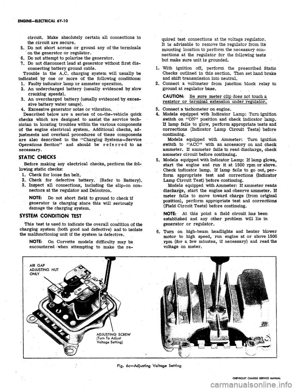
6c—Adjusting Voltage Setting
CHEVROLET CHASSIS SERVICE MANUAL
Page 337 of 659

ENGINE-ELECTRICAL 6Y-J2
Fig.
8c—Ammeter Method Test Connections
10.
Turn off ignition, disconnect battery ground cable,
and remove all test equipment.
11.
li the Delcotron meets the test specifications, the
problem is not in the generator.
12.
Ti the Delcotron fails to meet the test specifications,
remove it and perform bench tests and make repair
needed.
DELCOTRON DIODE AND FIELD TEST (Fig. 9c)
NOTE:
These tests will indicate good,, shorted
or open field or shorted diode but will not indi-
cate a failed open diode. If output was low and
following tests show good, refer to service op-
erations to determine cause and repair.
1.
Disconnect battery ground cable at battery.
2.
Positive diodes (Test A) connect an ohmmeter be-
tween "R" terminal and "BAT" terminal and note
Fig.
9c-Deicotron Diode and Field Test
reading, then reverse the leads at same terminals
and note this reading. Meter should read high re-
sistance in one direction and low in the other.
3.
Negative diodes (Test B) connect ohmmeter between
"R" terminal and "GRD" and note reading, then
reverse the leads and note this reading. Meter
should read high in one direction and low in the
other.
NOTE:
A high or low reading in both directions
indicates a defective diode.
4.
Open Field Check:
a. Connect an ohmmeter from "F" terminal to
"GRD"
terminal stud and note reading on the
lowest range scale. Meter should read 7 to
20 ohms.
b.
If meter reads zero or excessively high resist-
ance, the Delcotron is faulty.
5. If above tests indicate a defective Delcotron, remove
and completely check Delcotron as outlined under
''Service Operations".
INDICATOR LAMP/INITIAL FIELD
EXCITATION CIRCUIT TESTS (Fig. 10c)
On standard models the indicator lamp circuit provides
initial field excitation (causing lamp to glow). The light
is cancelled by closing the field relay which applies bat-
tery voltage to both sides of bulb (bulb goes out).
The indicator light should glow when ignition switch is
"ON"
and go out almost immediately when engine starts.
Ammeter equipped vehicles use the same initial field
excitation and control circuits as the indicator lamp ex-
cept the lamp is omitted. The continuity tests on both
type vehicles can be made as follows:
If Lamp Fails to Glow or Ammeter Fails to
Function the Possible Causes are:
1.
Faulty bulb or bulb socket.
2.
Faulty ammeter.
3.
An open circuit in wiring, regulator, or field.
4.
A shorted positive diode—(may also cause glow with
ignition switch "OFF").
TEST AS FOLLOWS:
1.
Disconnect connector from regulator and turn
ignition switch to "ON". Connect a test lamp from
connector terminal "4" to ground (fig. 10c, Step 1)
and note test lamp.
a. Lamp fails to glow—check for faulty bulb, socket
or open circuit between switch and regulator con-
nector. Repair as needed.
b.
Light goes on—failure is in regulator, Delcotron,
or wire between "F" terminals on regulator and
Delcotron. Go to Step 2.
2.
Disconnect lamp lead at ground end and connect be-
tween connector "F" and "4" terminals (fig. 10c,
Step 2), and note lamp:
a. Test Lamp glows—problem is in regulator. An
open circuit in regulator or relay is stuck dosed.
See "Service Operations" for repair.
b.
Fails to glow—problem is in wire between "F"
terminals on generator and regulator or infield
windings. Go to Step 3.
3.
Disconnect test lamp at connector "F" terminal and
CHEVROLET CHASSIS SERVICE MANUAL
Page 339 of 659
ENGINE-ELECTRICAL 6Y-14
VOLTMETER
WIRING HARNESS
CONNECTOR
Fig.
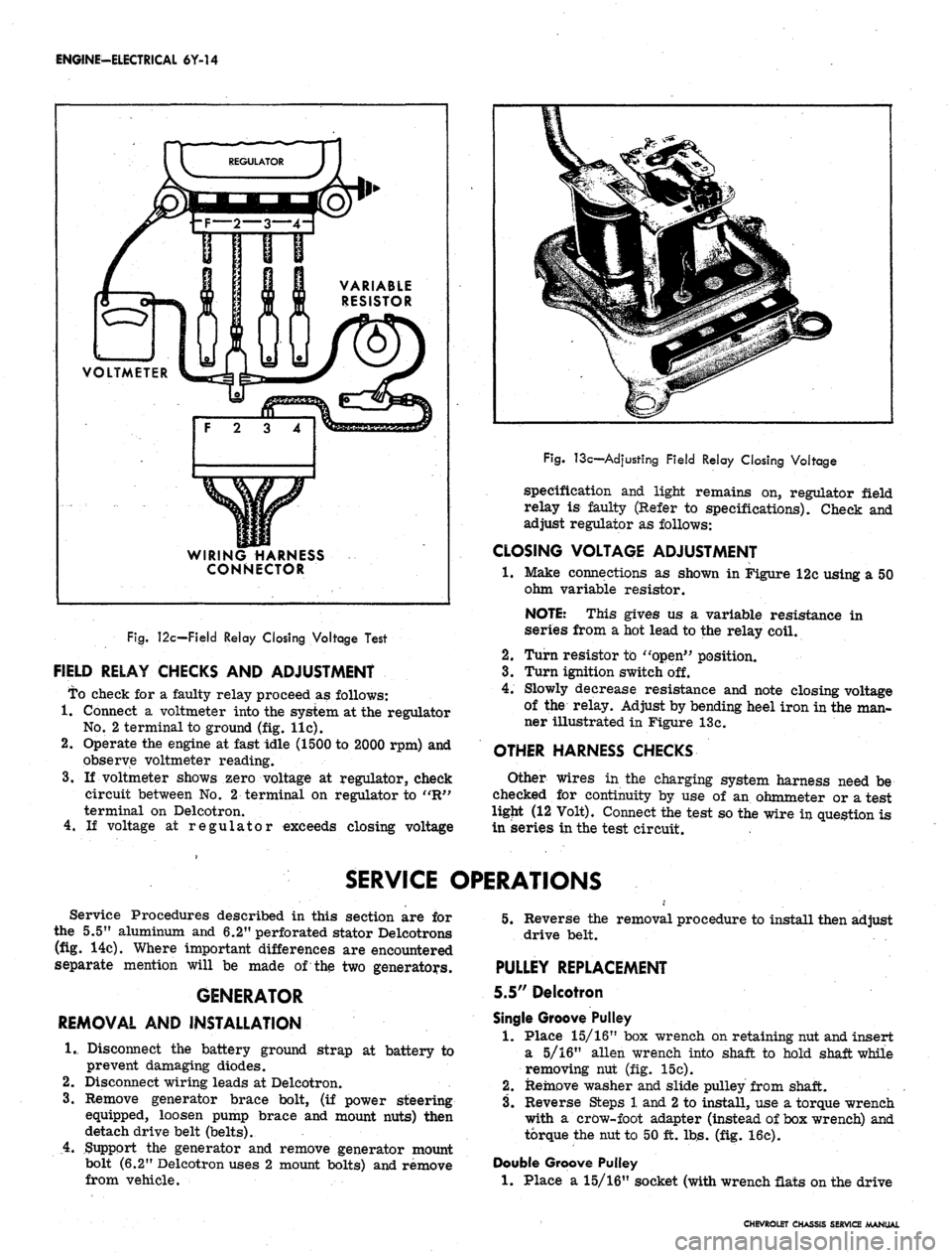
12c—Field Relay Closing Voltage Test
FIELD RELAY CHECKS AND ADJUSTMENT
To check for a faulty relay proceed as follows:
1.
Connect a voltmeter into the system at the regulator
No.
2 terminal to ground (fig. lie).
2.
Operate the engine at fast idle (1500 to 2000 rpm) and
observe voltmeter reading.
3.
If voltmeter shows zero voltage at regulator, check
circuit between No. 2 terminal on regulator to "R"
terminal on Delcotron.
4.
If voltage at regulator exceeds closing voltage
Fig.
13c—Adjusting Field Relay Closing Voltage
specification and light remains on, regulator field
relay is faulty (Refer to specifications). Check and
adjust regulator as follows:
CLOSING VOLTAGE ADJUSTMENT
•1.
Make connections as shown in Figure 12c using a 50
ohm variable resistor.
NOTE: This gives us a variable resistance in
series from a hot lead to the relay coil.
2.
Turn resistor to "open" position.
3.
Turn ignition switch off.
4.
Slowly decrease resistance and note closing voltage
of the relay. Adjust by bending heel iron in the man-
ner illustrated in Figure 13c.
OTHER HARNESS CHECKS
Other wires in the charging system harness need be
checked for continuity by use of an ohmmeter or a test
ligjit (12 Volt). Connect the test so the wire in question is
in series in the test circuit.
SERVICE OPERATIONS
Service Procedures described in this section are for
the 5.5" aluminum and 6.2" perforated stator Delcotrons
(fig. 14c). Where important differences are encountered
separate mention will be made of the two generators.
GENERATOR
REMOVAL AND INSTALLATION
1.
Disconnect the battery ground strap at battery to
prevent damaging diodes.
2.
Disconnect wiring leads at Delcotron.
3.
Remove generator brace bolt, (if power steering
equipped, loosen pump brace and mount nuts) then
detach drive belt (belts).
4.
Support the generator and remove generator mount
bolt (6.2" Delcotron uses 2 mount bolts) and remove
from vehicle.
5.
Reverse the removal procedure to install then adjust
drive belt.
PULLEY REPLACEMENT
5.5" Delcotron
Single Groove Pulley
1.
Place 15/16" box wrench on retaining nut and insert
a 5/16" alien wrench into shaft to hold shaft while
removing nut (fig. 15c).
2.
Remove washer and slide pulley from shaft.
3.
Reverse Steps 1 and
2
to install, use a torque wrench
with a crow-foot adapter (instead of box wrench) and
torque the nut to 50 ft. lbs. (fig. 16c).
Double Groove Pulley
1.
Place a 15/16" socket (with wrench flats on the drive
CHEVROLET CHASSIS SERVICE MANUAL
Page 346 of 659
ENGINE-ELECTRICAL
6Y-21
Fig.
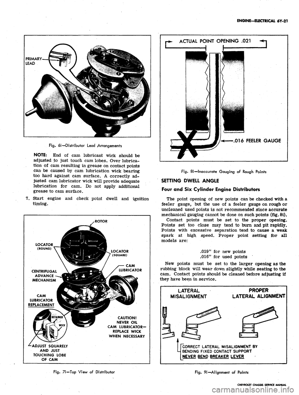
6i—Distributor Lead Arrangements
NOTE:
End of cam
lubricant wick should
be
adjusted
to
just touch
cam
lobes. Over lubrica-
tion
of cam
resulting
in
grease
on
contact points
can-
be
caused
by cam
lubrication wick bearing
too hard against
cam
surface.
A
correctly
ad-
justed
cam
lubricator wick will provide adequate
lubrication
for cam. Do not
apply additional
grease
to cam
surface.
7.
Start engine
and
check point dwell
and
ignition
timing.
ACTUAL
POINT OPENING
.021
.016
FEELER GAUGE
LOCATOR ___JH^H
(ROUND)
V~^3H|
CENTRIFUGAL
\
jdft
ADVANCE
-~-»JBlMBl
MECHANISM
«H
CAM g^k. / X
LUBRICATOR
V^^^
REPLACEMENT
^£9
^-ADJUST
SQUARELY
AND
JUST
TOUCHING
LOBE
OF
CAM
.ROTOR
I^^I^BL
LOCATOR
(PBV 7
(SQUARE)
SBSSF
/
WWjga^/
^/
LUBRICATOR
H^f
CAUTION!
S5y
NEVER
OIL
•-^
CAM
LUBRICATOR-
REPLACE
WICK
WHEN
NECESSARY
Fig.
8i—Inaccurate Gauging
of
Rough Points
SETTING DWELL ANGLE
Four
and Six
Cylinder Engine Distributors
The point opening
of new
points
can be
checked with
a
feeler gauge,
but the use of a
feeler gauge
on
rough
or
uncleaned used points
is not
recommended since accurate
mechanical gauging cannot
be
done
on
such points (fig. 8i).
Contact points must
be set to the
proper opening.
Points
set too
close
may
tend
to
burn and
pit
rapidly.
Points with excessive separation tend
to
cause
a
weak
spark
at
high speed. Proper point setting
for all
models
are:
.019"
for new
points
.016"
for
used points
New points must
be set to the
larger opening
as the
rubbing block will wear down slightly while seating
to the
cam. Contact points should
be
cleaned before adjusting
if
they have been
in
service.
LATERAL
MISALIGNMENT
PROPER
LATERAL
ALIGNMENT
pCORRECT
LATERAL MISALIGNMENT
BY
M
BENDING FIXED CONTACT SUPPORT
[NEVER
BEND BREAKER LEVER
Fig.
7i—Top View
of
Distributor
Fig.
9i—Alignment
of
Points
CHEVROLET
CHASSIS SERVICE /MANUAL
Page 347 of 659
ENGINE-ELECTRICAL 6Y-22
ADJUST DWELL
ANGLE SETTING OR
POINT OPENING
Fig.
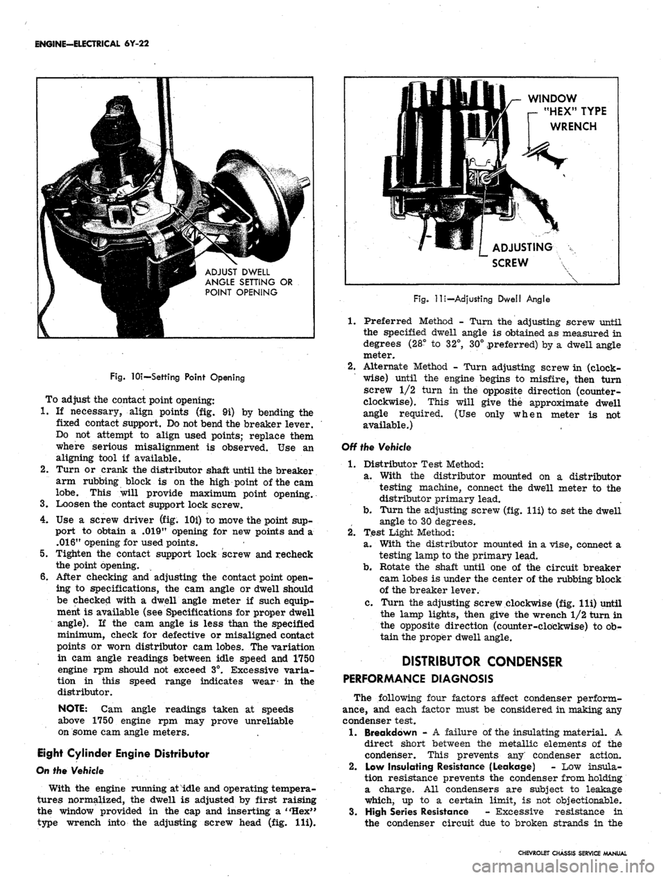
lOi—Settihg Point Opening
To adjust the contact point opening:
1.
If necessary, align points (fig. 9i) by bending the
fixed contact support. Do not bend the breaker lever.
Do not attempt to align used points; replace them
where serious misalignment is observed. Use an
aligning tool if available.
2.
Turn or crank the distributor shaft until the breaker
arm rubbing block is on the high point of the cam
lobe.
This will provide maximum point opening.
3.
Loosen the contact support lock screw.
4.
Use a screw driver (fig. lOi) to move the point sup-
port to obtain a .019" opening for new points and a
.016"
opening for used points.
5.
Tighten the contact support lock screw and recheck
the point opening.
6. After checking and adjusting the contact point open-
ing to specifications, the cam angle or dwell should
be checked with a dwell angle meter if such equip-
ment is available (see Specifications for proper dwell
angle).
If the cam angle is less than the specified
minimum, check for defective or misaligned contact
points or worn distributor cam lobes. The variation
in cam angle readings between idle speed and 1750
engine rpm should not exceed 3°. Excessive varia-
tion in this speed range indicates wear- in the
distributor.
NOTE:
Cam angle readings taken at speeds
above 1750 engine rpm may prove unreliable
on some cam angle meters.
Eight Cylinder Engine Distributor
On the Vehicle
With the engine running at idle and operating tempera-
tures normalized, the dwell is adjusted by first raising
the window provided in the cap and inserting a "Hex"
type wrench into the adjusting screw head (fig. Hi).
WINDOW
r- "HEX" TYPE
WRENCH
ADJUSTING
SCREW
Fig.
-lli—Adjusting Dwell Angle
1.
Preferred Method - Turn the adjusting screw until
the specified dwell angle is obtained as measured in
degrees (28° to 32°, 30° preferred) by a dwell angle
meter.
2.
Alternate Method - Turn adjusting screw in (clock-
wise) until the engine begins to misfire, then turn
screw 1/2 turn in the opposite direction (counter-
clockwise). This will give the approximate dwell
angle required. (Use only when meter is not
available.)
Off the Vehicle
1.
Distributor Test Method:
a. With the distributor mounted on a distributor
testing machine, connect the dwell meter to the
distributor primary lead.
b.
Turn the adjusting screw (fig. lli) to set the dwell
angle to 30 degrees.
2.
Test Light Method:
a. With the distributor mounted in a vise, connect a
testing lamp to the primary lead.
b.
Rotate the shaft until one of the circuit breaker
cam lobes is under the center of the rubbing block
of the breaker lever.
c. Turn the adjusting screw clockwise (fig. lli) until
the lamp lights, then give the wrench 1/2 turn in
the opposite direction (counter-clockwise) to ob-
tain the proper dwell angle.
DISTRIBUTOR CONDENSER
PERFORMANCE DIAGNOSIS
The following four factors affect condenser perform-
ance,
and each factor must be considered in making any
condenser test.
1.
Breakdown - A failure of the insulating material. A
direct short between the metallic elements of the
condenser. This prevents any' condenser action.
2.
Low Insulating Resistance (Leakage) - Low insula-
tion resistance prevents the condenser from holding
a charge. All condensers are subject to leakage
which, up to a certain limit, is not objectionable.
3.
High Series Resistance - Excessive resistance in
the condenser circuit due to broken strands in the
CHEVROLET CHASSIS SERVICE MANUAL
Page 352 of 659
ENGINE-ELECTRICAL 6Y-27
timing mark on pulley lines up with timing tab.
2.
Position distributor to opening in block in normal
installed attitude (fig. 15i), noting position of vacuum
control unit.
3.
Position rotor to point toward front of engine (with
distributor housing held in installed attitude), then
turn rotor counter-clockwise approximately 1/8 turn
more toward left cylinder bank and push distributor
down to engine camshaft. It may be necessary to ro-
tate rotor slightly until camshaft engagement is felt.
4.
While pressing firmly down on distributor housing,
kick starter over a few times to make sure oil pump
shaft is engaged. Install hold-down clamp and bolt
and snug up bolt.
5. Turn distributor body slightly until points just open
and tighten distributor clamp bolt.
6. Place distributor cap in position and check to see
that rotor lines up with terminal for No. 1 spark
plug.
7. Install cap, check all high tension wire connections
and connect spark plug wires if they have been re-
moved. It is important that the wires be installed in
their location in the supports.
NOTE:
The brackets are numbered to show the
correct installation. Wires must be installed as
indicated to prevent cross firing.
8. Connect vacuum line to distributor and distributor
primary wire to coil terminal.
9. Start engine and set timing as described under Turn-
Up in Section 6.
BREAKERLESS (MAGNETIC PULSE)
DISTRIBUTOR
REMOVAL (CORVETTE)
1.
If vehicle is equipped with radio, remove three bolts
securing ignition shield over distributor and coil.
One bolt is accessible from the top of shield, the
other two are at rear of shield, facing firewall.
2.
Disconnect tachometer drive cables from distributor
housing.
3.
Disconnect pickup coil leads at connector.
4.
Remove distributor cap.
5. Crank engine so rotor is in position to fire No. 1
cylinder and timing mark on harmonic balancer is
indexed with pointer.
6. Remove vacuum line from distributor.
7. Remove distributor clamping screw and hold-down
clamp.
8. Remove distributor and distributor-to-block gasket.
It will be noted that the rotor will rotate as the
distributor is pulled out of the block. Mark the re-
lationship of the rotor and the distributor housing
after removal so that the rotor can be set in the
same position when the distributor is being installed.
DISASSEMBLY (Fig. 16i)
NOTE:
If a distributor is being disassembled
for replacement of the stationary magnetic
pickup assembly only, it will be necessary to
perform only Steps 3, 4, 5, 7, 8, 9, and 12 of the
service procedure listed below.
1.
Remove screws securing rotor and remove rotor.
2.
Remove centrifugal weight springs and weights.
3.
Remove the tachometer drive gear from the distribu-
tor (Corvette only).
4.
Remove roll pin, then remove distributor drive gear
and washer.
CAUTION: To prevent
magnet, support drive gear
;e to the permanent
?n
driving out roll
pin.
5. Remove drive shaft assembly.
6. Remove centrifugal weight support and timer core
from drive shaft.
7. Remove connector from pickup coil leads.
8. Remove retaining ring which secures magnetic
core support plate to distributor shaft bushing in
housing.
9. As a unit, remove the entire magnetic pickup assem-
bly from the distributor housing.
10.
Remove brass washer and felt pad.
11.
Remove vacuum advance unit.
12.
To reassemble distributor, perform the above steps
in reverse order.
INSTALLATION (CORVETTE)
1.
Check to see that the engine is at firing position for
No.
1 cylinder (timing mark on harmonic balancer
indexed with pointer).
2.
Position a new distributor-to-block gasket on the
block.
3.
Before installing distributor, index rotor with hous-
ing as noted when distributor was removed. Install
distributor in block so that vacuum diaphragm faces
approximately 45° forward on the right side of the
engine and the rotor points toward contact in cap for
No.
1 cylinder.
4.
Replace distributor clamp leaving screw loose
enough to allow distributor to be turned for timing
adjustment.
5. Install spark plug wires in distributor cap. Place
wire for No. 1 cylinder in tower (marked on old cap
during disassembly) then install remaining wires
clockwise around the cap according to the firing
order (1-8-4-3-6-5-7-2).
6. Attach distributor to coil primary wires.
7. Replace distributor cap.
8. Adjust timing and then fully tighten distributor clamp
screw.
9. Attach vacuum line to distributor.
10.
Connect tachometer drive cables to distributor body.
11.
Replace ignition shields.
DISTRIBUTOR OFF-ENGINE TEST
The distributor's centrifugal and vacuum advance can
be checked in a distributor testing machine or synchro-
scope specially adapted or designed to accommodate this
type distributor. However, since this involves removing
the distributor from the engine, this test may be post-
poned until other system checks have been made. A dwell
reading cannot be obtained on this distributor and it is not
likely that the centrifugal or vacuum advance will be a
cause of trouble.
COIL REPLACEMENT
1.
Disconnect ignition switch and distributor leads from
CHEVROLET CHASSIS SERVICE MANUAL
Page 358 of 659
ENGINE-ELECTRICAL 6Y-33
O
V-8 ENGINE
STARTING MOTOR
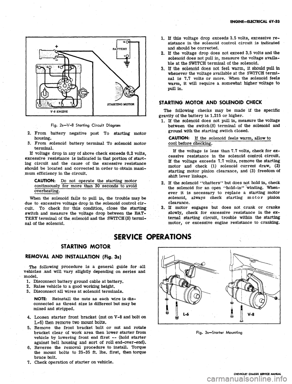
Fig.
2s—V-8 Starting Circuit Diagram
2.
3.
From battery negative post
To
starting motor
housing.
From solenoid battery terminal
To
solenoid motor
terminal.
If voltage drop
in
any
of
above check exceeds 0.2 volts,
excessive resistance
is
indicated in that portion
of
start-
ing circuit
and the
cause
of the
excessive resistance
should
be
located
and
corrected
in
order to obtain maxi-
mum efficiency in the circuit.
CAUTION:
Do not
operate
the
starting motor
continuously
for
more than
30
seconds
to
avoid
overheating.
When
the
solenoid fails
to
pull
in, the
trouble may be
due
to
excessive voltage drop in the solenoid control cir-
cuit.
To
check
for
this condition, close
the
starting
switch
and
measure
the
voltage drop between
the
BAT-
TERY terminal of the solenoid and the
SWITCH (S)
termi-
nal
of
the solenoid.
1.
If
this voltage drop exceeds 3.5 volts, excessive
re-
sistance
in the
solenoid control circuit
is
indicated
and should be corrected.
2.
If the
voltage drop does not exceed 3.5 volts and the
solenoid does not pull in, measure the voltage availa-
ble
at
the SWITCH terminal
of
the solenoid.
3.
If the
solenoid does
not
feel warm,
it
should pull
in
whenever the voltage available
at
the SWITCH termi-
nal
is 7.7
volts
or
more. When
the
solenoid feels
warm,
it
will require
a
somewhat higher voltage
to
pull in.
STARTING MOTOR AND SOLENOID CHECK
The following checks
may be
made
if the
specific
gravity of the battery
is
1.215
or
higher.
1.
If the
solenoid does
not
pull in, measure the voltage
between
the
switch
(S)
terminal
of the
solenoid
and
ground with the starting switch closed.
CAUTION:
If the
solenoid feels warm, allow
to
cool before checking.
If
the
voltage
is
less than 7.7 volts, check for ex-
cessive resistance
in the
solenoid control circuit.
If
the
voltage exceeds 7.7 volts, remove the starting
motor
and
check
(1)
solenoid current draw,
(2)
starting motor pinion clearance,
and (3)
freedom of
shift lever linkage.
2.
If
the solenoid "chatters" but does not hold in, check
the solenoid
for an
open "hold-in" 'winding. When-
ever
it is
necessary
to
replace
a
starting motor
solenoid, always check starting motor pinion
clearance.
3.
If
motor engages
but
does
not
crank
or
cranks
slowly, check
for
excessive resistance
in the ex-
ternal starting circuit, trouble within
the
starting
motor,
or
excessive engine resistance
to
cranking.
SERVICE OPERATIONS
STARTING MOTOR
REMOVAL AND INSTALLATION (Fig.
3s)
The following procedure
is a
general guide
for all
vehicles
and
will vary slightly depending
on
series
and
model.
1.
Disconnect battery ground cable at battery.
2.
Raise vehicle
to a
good working height.
3.
Disconnect all wires
at
solenoid terminals.
NOTE: Reinstall
the
nuts
as
each wire
is
dis-
connected
as
thread size
is
different but may be
mixed and stripped.
4.
Loosen starter front bracket (nut on V-8 and bolt on
L-6) then remove two mount bolts.
5.
Remove
the
front bracket bolt
or nut and
rotate
bracket clear
of
work area then lower starter from
vehicle
by
lowering front end first
—
(hold starter
against bell housing
and
sort
of
roll end-over-end).
6. Reverse
the
removal procedure
to
install. Torque
the mount bolts
to
25-35
ft.
lbs. first, then torque
brace bolt.
7.
Check operation
of
starter on vehicle.
Fig.
3s—Starter Mounting
CHEVROLET CHASSIS SERVICE MANUAL
Page 363 of 659
CLUTCH AND TRANSMISSIONS 7-4
5.
Install Tool J-5824 to support the clutch assembly
during removal.
NOTE: Look for "X" mark on flywheel and on
clutch cover. If MX" mark is not evident, prick
punch marks on flywheel and clutch cover for
indexing purposes during installation.
6. Loosen the clutch-to-flywheel attaching bolts evenly
1 turn at a time until spring pressure is released,
then remove the bolts, and remove clutch assembly.
Installation to Vehicle
Clean pressure plate and flywheel face. (They should
be free of oil, grease, metal deposits or burned spots).
1.
Position the clutch disc and pressure plate in relar
tive installed position and support them with align-
ment Tool J-5824.
NOTE: The driven disc on the 4 and 6 cylinder
engines is installed with the damfper springs to
the flywheel side; the V-8 is opposite, however,
THE GREASE SLINGER IS ALWAYS ON THE
TRANSMISSION SIDE.
2.
Turn clutch assembly until "X" mark on cover lines
up with "X" mark oh flywheel, then align cover bolt
holes to nearest flywheel holes.
3.
Install a bolt in every hole and tighten down evenly
and gradually until tight (to avoid possible clutch
distortion).
NOTE: Cover loads are as high as 1-1/4 tons.
4.
Remove pilot tool.
5.
Unhook clutch fork and lubricate ball socket and fork
fingers at release bearing end with a high melting
point grease such as graphite and reinstall fork on
ball stud. On Corvette models use Moly Grease.
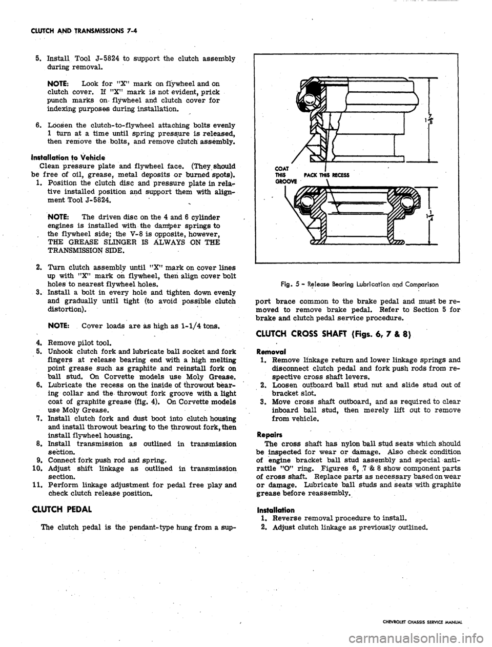
6. Lubricate the recess on the inside of throwout bear-
ing collar and the throwout fork groove with a light
coat of graphite grease (fig. 4). On Corvette models
use Moly Grease.
7.
Install clutch fork and dust boot into clutch housing
and install throwout bearing to the throwout fork, then
install flywheel housing.
8. Install transmission as outlined in transmission
section.
9. Connect fork push rod and spring.
10.
Adjust shift linkage as outlined in transmission
section.
11.
Perform linkage adjustment for pedal free play and
check clutch release position.
CLUTCH PEDAL
The clutch pedal is the pendant-type hung from a sup-
Fig. 5 - Release Bearing Lubrication and Comparison
port brace common to the brake pedal and must be re-
moved to remove brake pedal. Refer to Section 5 for
brake and clutch pedal service procedure.
CLUTCH CROSS SHAFT (Figs. 6, 7 & 8)
Removal
1.
Remove linkage return and lower linkage springs and
disconnect clutch pedal and fork push rods from re-
spective cross shaft levers.
2.
Loosen outboard ball stud nut and slide stud out of
bracket slot.
3.
Move cross shaft outboard, and as required to clear
inboard ball stud, then merely lift out to remove
from vehicle.
Repairs
The cross shaft has nylon ball stud seats which should
be inspected for wear or damage. Also check condition
of engine bracket ball stud assembly and special anti-
rattle "O" ring. Figures 6, .7
&
8 show component parts
of cross shaft. Replace parts as necessary based on wear
or damage. Lubricate ball studs and seats with graphite
grease before reassembly.
Installation
1.
Reverse removal procedure to install.
2.
Adjust clutch linkage as previously outlined.
CHEVROLET CHASSIS SERVICE MANUAL
Page 373 of 659

CLUTCH AND TRANSMISSIONS 7-14
SPEED HEAVY DUTY TRANSMISSION
(WARNER MODEL T 16)
INDEX
General Description ......
Maintenance and Adjustments
Shift Linkage Adjustment
Side Cover ........
Removal .........
Disassembly
7-14
7-14
7-14
7-14
7-14
7-14
Assembly 7-14
Installation • 7-15
Other Maintenance
&
Adjustment
Operations See 3-Speed Saginaw Section
Transmission Replacement . . . See 3-Speed Saginaw Section
GENERAL DESCRIPTION
The Borg-Warner heavy duty three speed fully syn-
chronized (all forward gears) transmission incorporates
helical gears throughout specially designed to provide
high torque capacity, and gear teeth proportion to operate
at high speeds with neither excessive heat generation nor
excessive frictional losses. Shafts, bearings, high ca-
pacity clutches and other precision parts are held to
close limits providing proper clearances necessary for
durability during extended heavy usage.
The main drive gear is supported by a heavy duty ball
bearing at the front end of the transmission case and is
piloted at its front end in an oil impregnated bushing
mounted in the engine crankshaft. The front end of the
mainshaft is piloted in a row of roller bearings set into
the hollow end of the main drive gear and the rear end
is carried by a heavy duty ball bearing mounted in the
front of the extension housing.
The countergear is carried on a double row of rollers
at both ends while thrust is taken on thrust washers lo-
cated between the ends of the gear and the thrust bosses
in the case. An anti-rattle plate assembly at the front
of the countergear provides a constant spring tension be-
tween the counter and clutch gears to reduce torsional
vibrations. The reverse idler gear is carried on 25
roller bearings while thrust is taken on thrust washers
located between the ends of the gear and the thrust bosses
of the case.
Gear shifting is manual through shift control rods from
the shifter tube in the mast jacket to the rearward shift
lever of the side cover assembly for first and reverse
gear; and through a cross shaft assembly attached to the
forward side cover lever for second and third gear. All
three forward gears are fully synchronized. The syn-
chronizer assemblies consist of a clutch hub, clutch
sleeve, two clutch key springs and three energizer clutch
keys and are retained as an assembly on the main shaft
by a snap ring. The transmission may be used as an aid
in deceleration by downshifting in sequence without
double-clutching or any gear clashing. Reverse is not
synchronized, however, it is a helical gear to insure
quiet operation.
MAINTENANCE AND ADJUSTMENTS
Refer to similar procedures under the 3-speed Saginaw
Transmission Section for—Column Mounted Shift Linkage
Adjustment, Speedometer Driven Gear and Oil Seal Re-
placement, Extension Oil Seal Replacement and Trans-
mission Replacement. ~~
Camaro and Corvette Floor Shift Linkage Adjustment
(Fig.
lc)
1.
Set Lever (L), (K) in neutral position.
2.
Move Lever Assembly (A) and Levers (C), (D) to
neutral position and insert Locating Gauge (B) into
control Lever Bracket Assembly.
3.,
Install Rod (H) with Retainer (M) on Lever (L).
4.
With two Jam Nuts (G), (E) and Swivel (F) loose on
Rod (H) insert and attach Swivel with Retainer (N)
to Lever (D).
5.
Repeat steps 3 and 4 for Rod (J) and Levers (C
&
K).
6. Remove' Locating Gauge and check shift to insure
proper operation.
SIDE COVER ASSEMBLY
Removal
1.
Drain transmission and disconnect control rod and
cross shaft from side cover levers. *
2.
Remove nine cap screws securing the transmission
side cover assembly to transmission, case and re-
move cover assembly, shifting forks, and gasket.
Disassembly (Fig. 2C) '
1.
Remove shifting forks from shift lever assemblies.
2.
Remove nut and lock washer from each shift lever
shaft.
3.
Remove outer shift levers and lightly tap shift lever
shafts from assembly.
4.
Remove two steel balls, poppet spring, interlock pin
and interlock sleeve from cover.
5.
Remove "O" ring seals from shift lever shafts.
Assembly (Fig. 2C)
1.
Install new "O" ring seals to shift lever shafts.
2.
Install low and reverse shifter shaft and plate as-
sembly to cover.
3.
Place shifter shaft and plate assembly in neutral po-
sition, middle detent, and install interlock sleeve,
ball, poppet spring and interlock pin.
4.
Install remaining poppet ball and then install second
and third shifter shaft and plate assembly.
NOTE: Installation is easiest if shifter shaft
and plate assembly passes over ball in its neu-
tral position.
5.
Check clearance between end of interlock sleeve and
shifter shaft and plate cams when one plate is in
neutral and the other is shifted into gear position.
CHEVROLET CHASSIS SERVICE MANUAL
Page 383 of 659
CLUTCH AND TRANSMISSIONS 7-24
is at the full mark on the dip stick, it is just slightly be-
low the planetary gear unit. If additional oil is added,
bringing the oil level above the full mark, the planetary
unit will run in the oil, foaming and aerating the oil. This
aerated oil carried through the various oil pressure pas-
sages (low servo, reverse servo, clutch apply, converter,
etc.) may cause malfunction of the transmission assem-
bly, resulting in cavitation noise in the converter and
improper band or clutch application. Overheating may
also occur.
If the transmission is found consistently low on oil, a
thorough inspection should be made to find and correct
all external oil leaks.
PERIODIC OIL CHANGE
The transmission oil should be changed periodically as
recommended in Section 0, and whenever transmission is
to be removed from the vehicle for repairs.
1.
Run engine for one minute in neutral prior to chang-
ing.
2.
Be sure vehicle is level or raise from the rear only.
3.
Remove the oil pan drain plug and allow oil to drain
thoroughly into a pan or can.
Replace drain plug and refill with approximately two
quarts of oil specified in Section 0.
NOTE: To refill the transmission, remove dip
stick from oil filler tube and refill transmission
with oil specified in Section 0 using filler tube
and funnel J-4264. Then, after shifting into all
ranges at idle speed to fill all oil passages, the
engine should be run at 800-1000 rpm with the
transmission in Neutral until the oil warms up,
then add oil as required to raise the fluid level
to the full mark on the dip stick. Refill capacity
is approximately 2 qts.
4.
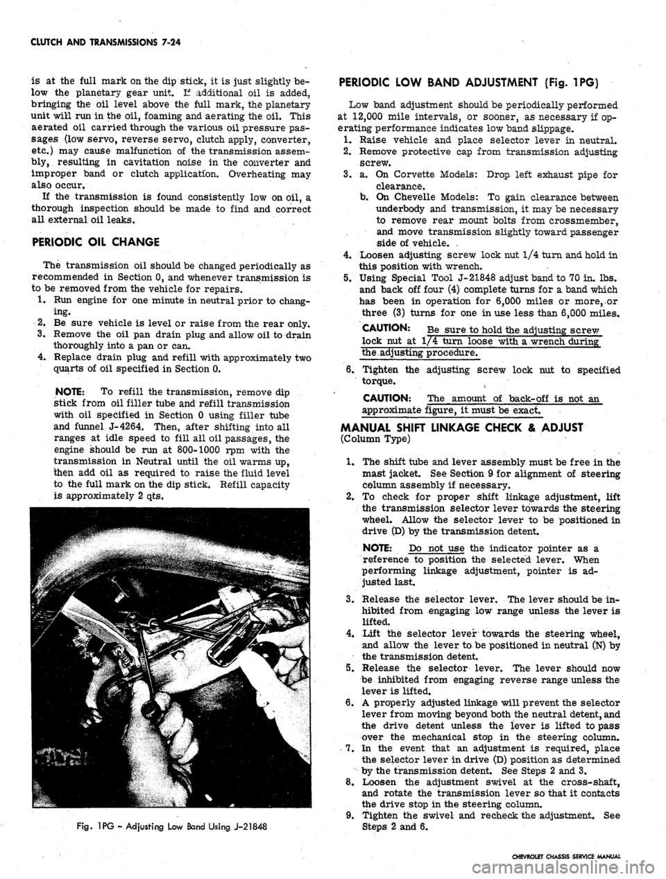
Fig.
1PG - Adjusting Low Band Using J-21848
PERIODIC LOW BAND ADJUSTMENT (Fig. 1PG)
Low band adjustment should be periodically performed
at 12,000 mile intervals, or sooner, as necessary if op-
erating performance indicates low band slippage.
1.
Raise vehicle and place selector lever in neutral.
2.
Remove protective cap from transmission adjusting
screw.
3.
a. On Corvette Models: Drop left exhaust pipe for
clearance.
b.
On Chevelle Models: To gain clearance between
underbody and transmission, it may be necessary
to remove rear mount bolts from crossmember,
and move transmission slightly toward passenger
side of vehicle. .
4.
Loosen adjusting screw lock nut 1/4 turn and hold in
this position with wrench.
5.
Using Special Tool J-21848 adjust band to 70 in. lbs.
and back off four (4) complete turns for a band which
has been in operation for 6,000 miles or more,.or
three (3) turns for one in use less than 6,000 miles.
CAUTION: Be sure to hold the adjusting screw
lock nut at 1/4 turn loose with a wrench during"
the.adjusting procedure.
6. Tighten the adjusting screw lock nut to specified
torque.
CAUTION: The amount of back-off is not an
approximate figure, it must be exact.
MANUAL SHIFT LINKAGE CHECK & ADJUST
(Column Type)
1.
The shift tube and lever assembly must be free in the
mast jacket. See Section 9 for alignment of steering
column assembly if necessary.
2.
To check for proper shift linkage adjustment, lift
the transmission selector lever towards the steering
wheel. Allow the selector lever to be positioned in
drive (D) by the transmission detent.
NOTE: Do not use the indicator pointer as a
reference to position the selected lever. When
performing linkage adjustment, pointer is ad-
justed last.
3.
Release the selector lever. The lever should be in-
hibited from engaging low range unless the lever is
lifted.
4.
Lift the selector lever towards the steering wheel,
and allow the lever to be positioned in neutral (N) by
the transmission detent.
5.
Release the selector lever. The lever should now
be inhibited from engaging reverse range unless the
lever is lifted.
6. A properly adjusted linkage will prevent the selector
lever from moving beyond both the neutral detent, and
the drive detent unless the lever is lifted to pass
over the mechanical stop in the steering column.
7.
In the event that an adjustment is required, place
the selector lever in drive (D) position as determined
by the transmission detent. See Steps 2 and 3.
8. Loosen the adjustment swivel at the cross-shaft,
and rotate the transmission lever so that it contacts
the drive stop in the steering column.
9. Tighten the swivel and recheck the adjustment. See
2 and 6.
CHEVROLET CHASSIS SERVICE MANUAL