suspension CHEVROLET CAMARO 1967 1.G Chassis Owner's Guide
[x] Cancel search | Manufacturer: CHEVROLET, Model Year: 1967, Model line: CAMARO, Model: CHEVROLET CAMARO 1967 1.GPages: 659, PDF Size: 114.24 MB
Page 187 of 659
FRONT SUSPENSION 3-23
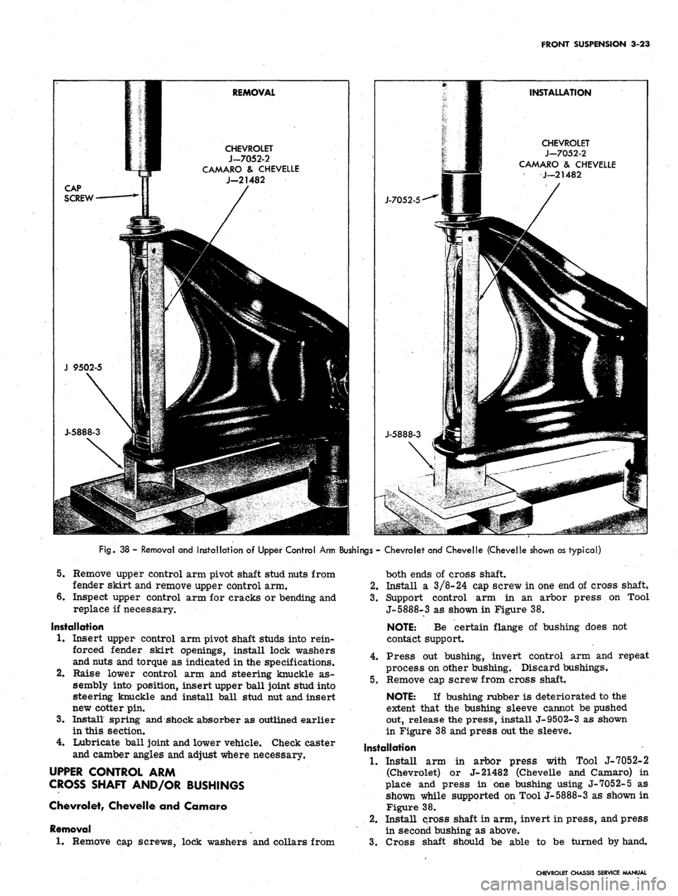
CHEVROLET
J-7052-2
CAMARO
& CHEVELLE
J-21482
CHEVROLET
J-7052-2
CAMARO
& CHEVELLE
J-21482
Fig.
38 - Removal and Installation of Upper Control Arm Bushings - Chevrolet and Chevelle (Chevelle shown as typical)
5.
Remove upper control arm pivot shaft stud nuts from
fender skirt and remove upper control arm.
6. Inspect upper control arm for cracks or bending and
replace if necessary.
Installation
1.
Insert upper control arm pivot shaft studs into rein-
forced fender skirt openings, install lock washers
and nuts and torque as indicated in the specifications.
Raise lower control arm and steering knuckle as-
sembly into position, insert upper ball joint stud into
steering knuckle and install ball stud nut and insert
new cotter pin.
Install spring and shock absorber as outlined earlier
in this section.
Lubricate ball joint and lower vehicle. Check caster
and camber angles and adjust where necessary.
UPPER CONTROL ARM
CROSS SHAFT AND/OR BUSHINGS
Chevrolet, Chevelle and Camaro
Removal
1.
Remove cap screws, lock washers and collars from
2.
3.
4.
both ends of cross shaft.
2.
Install a 3/8-24 cap screw in one end of cross shaft,
3.
Support control arm in an arbor press on Tool
J-5888-3 as shown in Figure 38.
NOTE: Be certain flange of bushing does not
contact support.
4.
Press out bushing, invert control arm and repeat
process on other bushing. Discard bushings.
5.
Remove cap screw from cross shaft.
NOTE: If bushing rubber is deteriorated to the
extent that the bushing sleeve cannot be pushed
out, release the press, install J-9502-3 as shown
in Figure 38 and press out the sleeve.
Installation
1.
Install arm in arbor press with Tool J-7052-2
(Chevrolet) or J-21482 (Chevelle and Camaro) in
place and press in one bushing using J-7052-5 as
shown while supported on Tool j-5888-3 as shown in
Figure 38.
2.
Install cross shaft in arm, invert in press, and press
in second bushing as above.
3.
Cross shaft should be able to be turned by hand.
CHEVROLET CHASSIS SERVICE MANUAL
Page 188 of 659
FRONT SUSPENSION 3-24
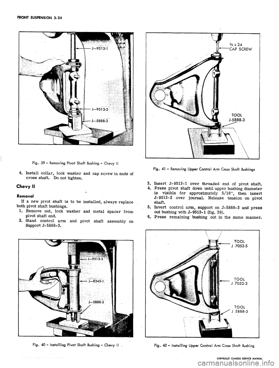
Fig.
39 - Removing Pivot Shaft Bushing - Chevy II
4.
Install collar, lock washer and cap screw in ends of
cross shaft. Do not tighten.
Chevy II
Removal
If a new pivot shaft is to be installed, always replace
both pivot shaft bushings.
1.
Remove nut, lock washer and metal spacer from
pivot shaft end.
2.
Stand control arm and pivot shaft assembly on
Support J-5888-3.
V
f
ff 3/a x 24
y* CAP SCREW
k
a
4f TOOL
i J-5888-3
••
Fig.
41 - Removing Upper Control Arm Cross Shaft Bushings
3.
Insert J-9513-1 over threaded end of pivot shaft.
4.
Press pivot shaft down until upper bushing diameter
is visible for approximately 5/16", then insert
J-9513-2 over journal. Release tension on pivot
shaft.
5.
Invert control arm, support on J-5888-3 and press
out bushing with J-9513-1 (fig. 39).
6. Press remaining bushing out in the same manner.
TOOL
J 7052-5
Fig.
40 - Installing Pivot Shaft Bushing - Chevy II
Fig. 42 - Installing Upper Control Arm Cross Shaft Bushing
CHEVROLET CHASSIS SERVICE MANUAL
Page 189 of 659
FRONT SUSPENSION 3-25
Installation
1.
Insert new bushing in control arm and over pivot
shaft.
2.
Support arm on J-5888-3 and insert Spacer J-
8345-1.
5.
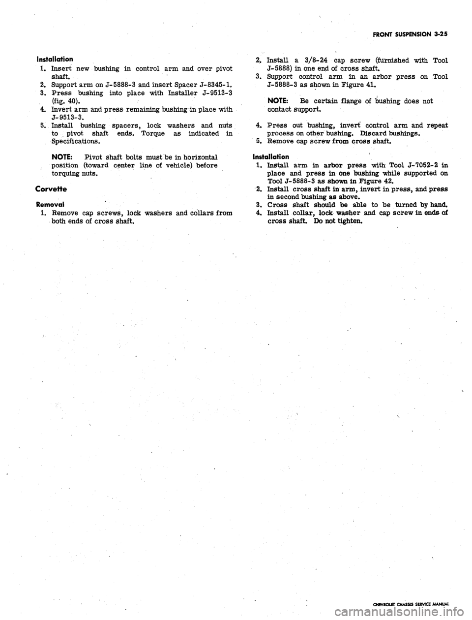
Press bushing into place with Installer J-9513-3
(fig. 40).
Invert arm and press remaining bushing in place with
J-9513-3.
Install bushing spacers, lock washers and nuts
to pivot shaft ends. Torque as indicated in
Specifications.
NOTE:
Pivot shaft bolts must be in horizontal
position (toward center line of vehicle) before
torquing nuts.
Corvette
Removal
1.
Remove cap screws, lock washers and collars from
both ends of cross shaft.
2.
Install a 3/8-24 cap screw (furnished with Tool
J- 5888) in one end of cross shaft.
3.
Support control arm in an arbor press on Tool
J-5888-3 as shown in Figure 41.
NOTE:
Be certain flange of bushing does not
contact support.
4.
Press out bushing, invert control arm and repeat
process on other bushing. Discard bushings.
5. Remove cap screw from cross shaft.
Installation
1.
Install arm in arbor press with Tool J-7052-2 in
place and press in one bushing while supported on
Tool J-5888-3 as shown in Figure 42.
2.
Install cross shaft in arm, invert in press, and press
in second bushing as above.
3.
Cross shaft should be able to be turned by hand.
4.
Install collar, lock washer and cap screw in ends of
cross shaft. Do not tighten.
CHEVROLET CHASSIS SERVICE MANUAL
Page 190 of 659
FRONT SUSPENSION 3-26
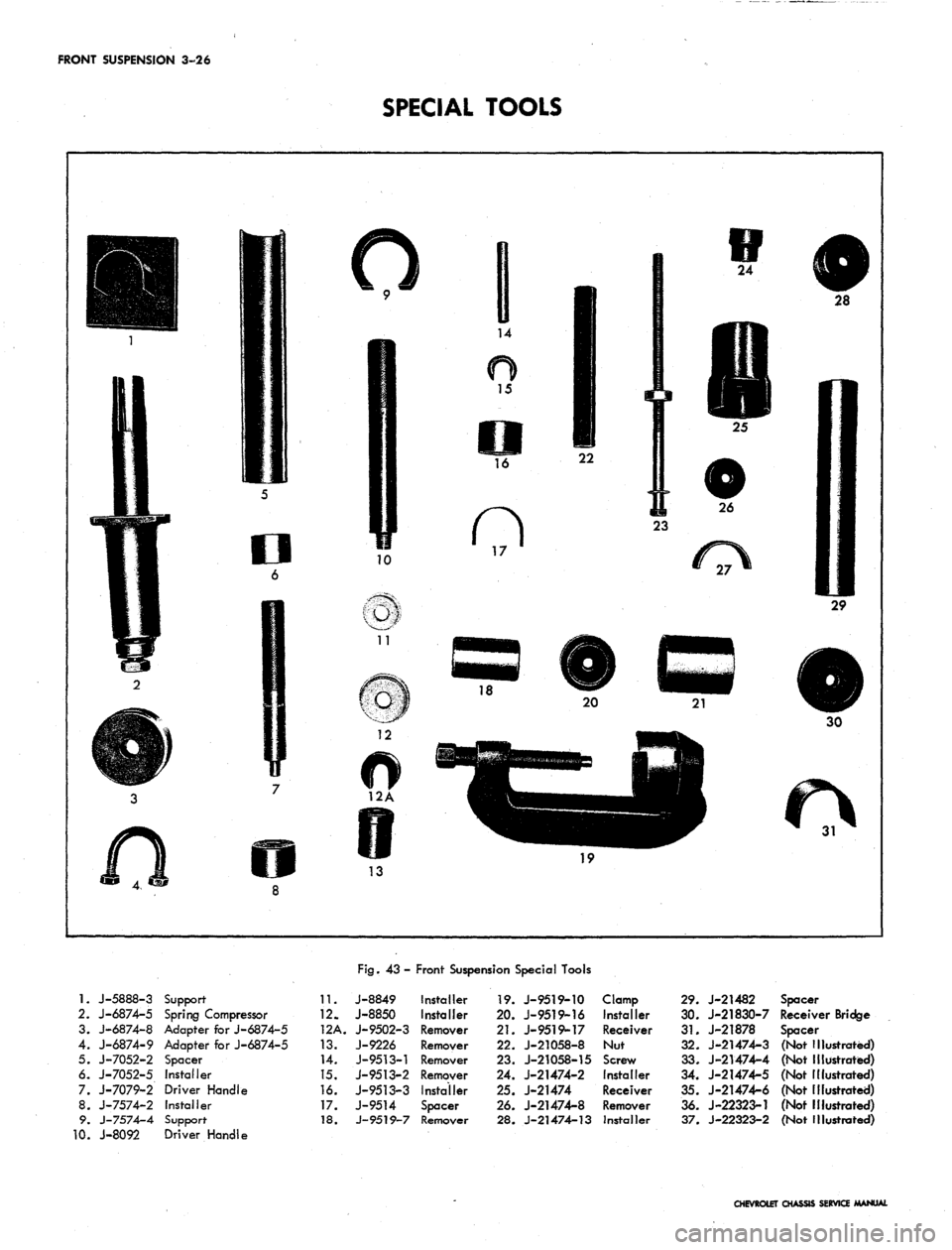
SPECIAL TOOLS
1.
J-5888-3
2.
J-6874-5
3. J-6874-8
4. J-6874-9
5. J-7052-2
6. J-7052-5
7. J-7079-2
8. J-7574-2
9. J-7574-4
0. J-8092
Support-
Spring Compressor
Adapter for J-6874-5
Adapter for J-6874-5
Spacer
Installer
Driver Handle
Installer
Support
Driver Handle
11.
12.
12A.
13.
14.
15.
16.
17.
18.
Fig.
43-
J-8849
J-8850
J-9502-3
J-9226
J-9513-1
J-9513-2
J-9513-3
J-9514
J-9519-7
Front Suspension Special Tools
Installer
Installer
Remover
Remover
Remover
Remover
Installer
Spacer
Remover
19.
J-9519-10
20.
J-9519-16
21.
J-9519-17
22.
J-21058-8
23.
J-21058-15
24.
J-21474-2
25.
J-21474
26.
J-21474-8
28.
J-21474-13
Clamp
Installer
Receiver
Nut
Screw
Installer
Receiver
Remover
Installer
29.
J-21482
30.
J-21830-7
31.
J-21878
32.
J-21474-3
33.
J-21474-4
34.
J-21474-5
35.
J-21474-6
36.
J-22323-1
37.
J-22323-2
Spacer
Receiver Bridge
Spacer
(Not Illustrated)
(Not Illustrated)
(Not Illustrated)
(Not illustrated)
(Not Illustrated)
(Not Illustrated)
CHEVROLET CHASSIS SERVICE MANUAL
Page 191 of 659
SECTION
4
REAR SUSPENSION
AND
DRIVE LINE
CONTENTS
OF
THIS SECTION
Page
Rear Suspension
4-1
Drive Line.
. 4-26
Rear Axle ......
4-26
Propeller Shaft
and
Universal Joints
Special Tools
4-37
4-43
REAR SUSPENSION
INDEX
General Description
4-1
Chevrolet
4-1
Chevelle
4-1
Chevy
n and
Camaro
. . . . . 4-2
Corvette
. . . . . . 4-3
Maintenance
and
Adjustments ...............
4-4
Riding Height Check (Chevrolet, Camaro,
Chevelle
and
Chevy
II) 4-5
Wheel Alignment (Corvette)
4-5
Wheel Bearing Adjustment (Corvette)
4-6
Component Parts Replacement (Chevrolet, Camaro,
Chevelle
and
Chevy
JJ) 4-7
Coil Spring
4-7
Chevrolet
4-7
Removal
4-7
Installation
4-7
Chevelle
4-8
Removal
4-8
4-8
Installation
.
Leaf Spring, Spring Seat Pads, Spring
Eye
Bushings
4-9
Chevy
H 4-9
Removal
4-9
Installation
4-9
Camaro
4-10
Removal
4-10
Installation
4-11
Shock Absorber
4-11
Chevrolet
and
Chevelle
. 4-11
Removal
4-11
Installation
. . 4-12
Chevy
II 4-12
Removal
4-12
Installation
4-rl2
Camaro
4-12
Removal
. 4-12
Installation
4-12
Control
Arm . . 4-12
Chevrolet Upper
4-12
Removal
. 4-12
Page
Bushing Replacement
. 4-13
Installation
4-14
Chevrolet Lower
4-14
Removal
4-14
Bushing Replacement
4-14
Installation
. 4-15
Chevelle Upper
and
Lower.
. 4-15
Removal
4-15
Bushing Replacement
4-15
Installation
4-17
Rear Suspension
Tie Rod
(Chevrolet)
. . .
......
. . . 4-17
Removal
4-17
Bushing Replacement
4-17
Installation
4-17
Component Parts Replacement (Corvette)
. . 4-17
Wheel Spindle
and
Support
4-17
Removal
4-17
Repairs
', . 4-17
Installation
4-18
Differential Carrier Support Bracket Replacement.
. 4-20
Shock Absorber
4-20
Removal
4-20
Installation
* .... 4-20
Strut
Rod and
Bracket
4-20
Removal
4-20
Repairs
4-21
Installation
4-21
Spring
4-21
Removal
4-21
Repairs
4-22
Installation
4-22
Torque Control
Arm 4-23
Removal
4-23
Repairs
. 4-23
Installation
4-24
Suspension Crossmember
4-24
Removal
4-24
Repairs—Isolation Mount
4-25
Installation
4-25
Stabilizer Shaft Replacement
4-25
GENERAL DESCRIPTION
CHEVROLET
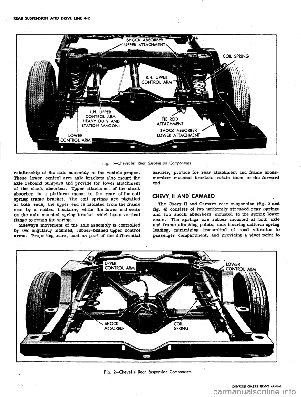
The link type rear suspension (fig. 1) has two lower
control arms which maintain proper axle to frame re-
lationship and also take the acceleration, drive and
braking forces. A single upper control arm on light-
duty models (or two upper control arms on heavy-duty
models and all station wagons) limits axle rotation when
drive, acceleration or braking forces are applied. Lateral
movement of the axle is restricted by the axle-to-frame
tie rod. Two full coil springs and two direct, double
acting shock absorbers are provided for additional ride
control.
CHEVELLE
The rear suspension (fig. 2) is of the four-link design
utilizing axle mounted, full coil springs and direct,
double-acting shock absorbers.
Two rubber-bushed lower control arms, stretching
slightly outboard from axle-mounted brackets to frame
side member mounted brackets, maintain fore and aft
CHEVROLET CHASSIS SERVICE MANUAL
Page 192 of 659
REAR SUSPENSION AND DRIVE LINE 4-2
SHOCK ABSORBER
UPPER ATTACHMENT
COIL SPRING
\
R.H. UPPER
CONTROL ARM
LH.
UPPER
CONTROL ARM
(HEAVY DUTY AND
STATION WAGON)
TIE ROD
ATTACHMENT
SHOCK ABSORBER
LOWER ATTACHMENT
LOWER
CONTROL ARM
Fig.
1—Chevrolet Rear Suspension Components
relationship of the axle assembly to the vehicle proper.
These lower control arm axle brackets also mount the
axle rebound bumpers and provide for lower attachment
of the shock absorber. Upper attachment of the shock
absorber is a platform mount to the rear of the coil
spring frame bracket. The coil springs are pigtailed
at both ends; the upper end is isolated from the frame
seat by a rubber insulator, while the lower end seats
on the axle mounted spring bracket which has a vertical
flange to retain the spring.
Sideways movement of the axle assembly is controlled
by two angularly mounted, rubber-bushed upper control
arms.
Projecting ears, cast as part of the differential
carrier, provide for rear attachment and frame cross-
member mounted brackets retain them at the forward
end.
CHEVY 11 AND CAMARO
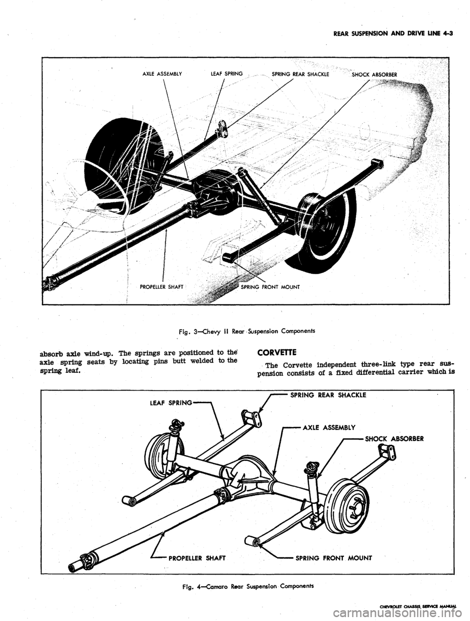
The.Chevy n and Camaro rear suspension (fig. 3 and
fig.
4) consists of two uniformly stressed rear springs
and two shock absorbers mounted to the spring lower
seats.
The
.
springs are rubber mounted at both axle
and frame attaching points, thus insuring uniform spring
loading, minimizing transmittal of road vibration to
passenger compartment, and providing a pivot point to
•MMMi
MMM—Hi—1—1——1——1MMMMiM_
[•?{aw-i
'
"'
i
\ SHOCK^^BBB^^B(^^CO1L
ABSORBER ^HH^ SPRING
g^8^"
_ LOWER
feSfcto^
CONTROL
ARM
Fig.
2—Chevelle Rear Suspension Components
CHEVROLET CHASSIS SERVICE MANUAL
Page 193 of 659
REAR SUSPENSION
AND
DRIVE LINE
4-3
AXLE ASSEMBLY
LEAF SPRING
SPRING REAR SHACKLE
SHOCK ABSORBER
Fig.
3—Chevy
II
Rear Suspension Components
absorb axle "wind-up.
The
springs
are
positioned
to
the*
axle spring seats
by
locating pins butt welded
to
the
spring
leaf.
CORVETTE
The Corvette independent three-link type rear
sus-
pension consists
of a
fixed differential carrier which
is
SPRING REAR SHACKLE
LEAF SPRING
SHOCK ABSORBER
SPRING FRONT MOUNT
Fig.
4—Comoro Rear Suspension Components
CHEVROLET CHASSIS SERVICE MANUAL
Page 194 of 659
REAR SUSPENSION AND DRIVE LINE
4-4
PROPELLER SHAFT
CARRIER FRONT SUPPORT
CAMBER CAM CONTROL ARM
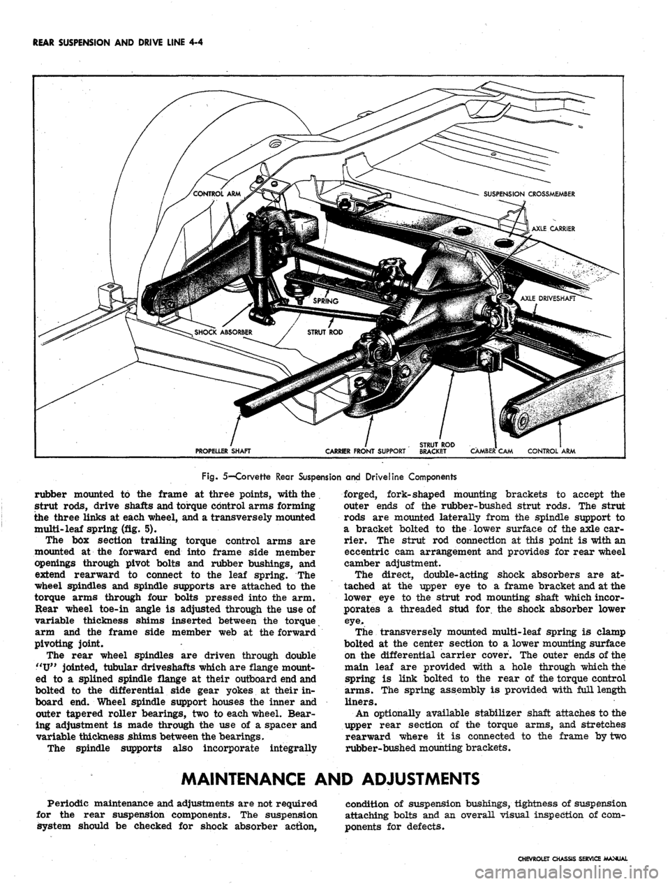
Fig. 5—Corvette Rear Suspension and Driveline Components
rubber mounted to the frame at three points, with the .
strut rods, drive shafts and torque control arms forming
the three links at each wheel, and a transversely mounted
multi-leaf spring (fig. 5).
The bbx section trailing torque control arms are
mounted at the forward end into frame side member
openings through pivot bolts and rubber bushings, and
extend rearward to connect to the leaf spring. The
wheel spindles and spindle supports are attached to the
torque arms through four bolts pressed into the arm.
Rear wheel toe-in angle is adjusted through the use of
variable thickness shims inserted between the torque
arm and the frame side member web at the forward
pivoting joint.
The rear wheel spindles are driven through double
"U"
jointed, tubular driveshafts which are flange mount-
ed to a splined spindle flange at their outboard end and
bolted to the differential side gear yokes at their in-
board end. Wheel spindle support houses the inner and
outer tapered roller bearings, two to each wheel. Bear-
ing adjustment is made through the use of a spacer and
variable thickness shims between the bearings.
The spindle supports also incorporate integrally
forged, fork-shaped mounting brackets to accept the
outer ends of the rubber-bushed strut rods. The strut
rods are mounted laterally from the spindle support to
a bracket bolted to the lower surface of the axle car-
rier. The strut rod connection at this point is with an
eccentric cam arrangement and provides for rear wheel
camber adjustment.
The direct, double-acting shock absorbers are at-
tached at the upper eye to a frame bracket and at the
lower eye to the strut rod mounting shaft which incor-
porates a threaded stud for. the shock absorber lower
eye.
The transversely mounted multi-leaf spring is clamp
bolted at the center section to a lower mounting surface
on the differential carrier cover. The outer ends of the
main leaf are provided with a hole through which the
spring is link bolted to the rear of the torque control
arms.
The spring assembly is provided with full length
liners.
An optionally available stabilizer shaft attaches to the
upper rear section of the torque arms, and stretches
rearward where it is connected to the frame by two
rubber-bushed mounting brackets.
MAINTENANCE AND ADJUSTMENTS
Periodic maintenance and adjustments are not required
for the rear suspension components. The suspension
system should be checked for shock absorber action,
condition of suspension bushings, tightness of suspension
attaching bolts and an overall visual inspection of com-
ponents for defects.
CHEVROLET CHASSIS SERVICE MANUAL
Page 195 of 659
REAR SUSPENSION AND DRIVE LINE 4-5
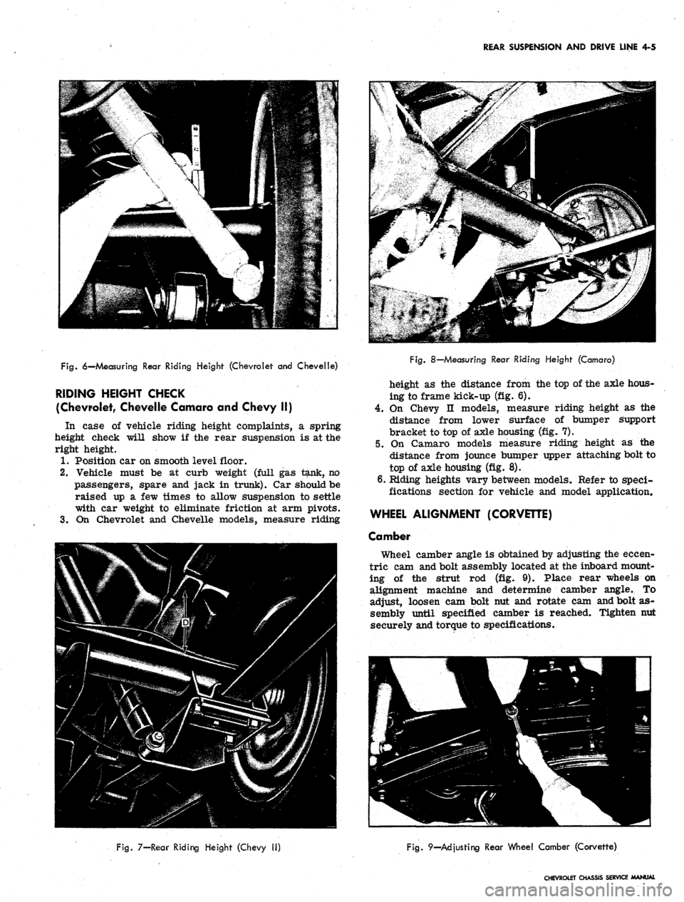
Fig.
6—Measuring Rear Riding Height (Chevrolet and Chevelle)
RIDING HEIGHT CHECK
(Chevrolet, Chevelle Camaro and Chevy II)
In case of vehicle riding height complaints, a spring
height check will show if the rear suspension is at the
right height.
1.
Position car on smooth level floor.
2.
Vehicle must be at curb weight (full gas tank, no
passengers, spare and jack in trunk). Car should be
raised up a few times to allow suspension to settle
with car weight to eliminate friction at arm pivots.
3.
On Chevrolet and Chevelle models, measure riding
Fig.
8—Measuring Rear Riding Height (Camaro)
height as the distance from the top of the axle hous-
ing to frame kick-up (fig. 6).
4.
On Chevy II models, measure riding height as the
distance from lower surface of bumper support
bracket to top of axle housing (fig. 7).
5.
On Camaro models measure riding height as the
distance from jounce bumper upper attaching bolt to
top of axle housing (fig. 8).
6. Riding heights vary between models* Refer to speci-
fications section for vehicle and model application.
WHEEL ALIGNMENT (CORVETTE)
Camber
Wheel camber angle is obtained by adjusting the eccen-
tric cam and bolt assembly located at the inboard mount-
ing of the strut rod (fig. 9). Place rear wheels on
alignment machine and determine camber angle. To
adjust, loosen cam bolt nut and rotate cam and bolt as-
sembly until specified camber is reached. Tighten nut
securely and torque to specifications.
Fig.
7—Rear Riding Height (Chevy II)
Fig.
9—Ad
justing
Rear Wheel Camber (Corvette)
CHEVROLET CHASSIS SERVICE MANUAL
Page 196 of 659
REAR SUSPENSION AND DRIVE LINE 4-6
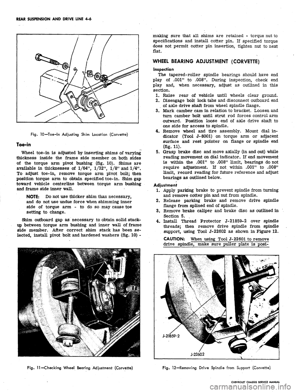
Fig.
10—Toe-in Adjusting Shim Location (Corvette)
Toe-in
Wheel toe-in is adjusted by inserting shims of varying
thickness inside the frame side member on both sides
of the torque arm pivot bushing (fig. 10). Shims are
available in thicknesses of
1/64",
1/32",
1/8" and 1/4".
To adjust toe-in, remove torque arm pivot bolt; then
position torque arm to obtain specified toe-in. Shim gap
toward vehicle centerline between torque arm bushing
and frame side inner wall.
NOTE: Do not use thicker shim than necessary,
and do not use undue force when shimming inner
side of torque arm - to do so may cause toe
setting to change.
Shim outboard gap as necessary to obtain solid stack-
up between torque arm bushing and inner wall of frame
side member. After correct shim stack has been se-
lected, install pivot bolt and hardened washers (fig. 10) -
making sure that all shims are retained - torque nut to
specifications and install cotter pin. If specified torque
does not permit cotter pin insertion, tighten nut to next
flat.
WHEEL BEARING ADJUSTMENT (CORVETTE)
inspection
The tapered-roller spindle bearings should have end
play of .001" to
.008".
During inspection, check end
play and, when necessary, adjust as outlined in this
section.
1.
Raise rear of vehicle until wheels clear ground.
2.
Disengage bolt lock tabs and disconnect outboard end
of axle drive shaft from wheel spindle flange.
3.
Mark camber cam in relation to bracket. Loosen and
turn camber bolt until strut rod forces control arm
outward. Position loose end of axle drive shaft to
one side for access to spindle.
4.
Remove wheel and tire assembly. Mount dial in-
dicator (Tool J-8001) on torque arm or adjacent
surface and rest pointer on flange or spindle end
(fig. H).
5.
Grasp brake disc and move axially (in and out) while
reading movement on dial indicator. If end movement
is within the .001" to .008" limit, bearings do not
require adjustment. If not within .001" to .008"
limit, record reading for future reference and adjust
bearings as outlined below.
Adjustment
1.
Apply parking brake to prevent spindle from turning
and remove cotter pin and nut from spindle.
2.
Release parking brake and remove drive spindle
flange from splined end of spindle.
3.
Remove brake caliper and brake disc as outlined in
Section 5.
4.
Install Thread Protector J-21859-2 over spindle
threads; then remove drive spindle from spindle
support, using Tool J-22602 as shown in Figure 12.
CAUTION: When using Tool J-22601 to remove
drive spindle, make sure puller plate is posi-
Fig.
11—Checking Wheel Bearing Adjustment (Corvette)
Fig. 12—Removing Drive Spindle from Support (Corvette)
CHEVROLET CHASSIS SERVICE MANUAL