light CHEVROLET CAMARO 1967 1.G Chassis Repair Manual
[x] Cancel search | Manufacturer: CHEVROLET, Model Year: 1967, Model line: CAMARO, Model: CHEVROLET CAMARO 1967 1.GPages: 659, PDF Size: 114.24 MB
Page 272 of 659
ENGINE 6-7
Tune Up should be checked whenever the Air Injection
Reactor System seems to be malfunctioning. Particular
care should be taken in checking items that affect fuel-air
ratio such as the crankcase ventilation system, the car-
buretor and the carburetor air cleaner. Carburetors and
distributors for engines with the Air Injection Reactor
System are designed, particularly, for these engines;
therefore, they must not be interchanged with or replaced
by a carburetor or distributor designed for an engine
without the Air Injection Reactor System.
Choke Adjustment (Fig. 11)
With Remote Choke
1.
Remove air cleaner and check to see that choke
valve and rod move freely.
2.
Disconnect choke r*od at choke lever.
Check choke adjustment as follows:
On all except 275 hp 327 cu. in. engines, hold
choke valve closed and pull rod up against stop. The
top of choke rod end should be 1/2 - 1 rod diameter
4.
5.
above top of hole in choke valve lever.
On 275 hp 327 cu. in. engines, hold choke valve
closed and push rod down against stop on thermostat
bracket. The top of the choke rod should be 1/2 - 1
rod diameter below the top of the hole in the choke
lever.
If necessary, adjust rod length by bending rod at off-
set. (Bend must be such that rod enters choke lever
hole freely and squarely.)
Connect rod at choke lever and install air cleaner.
3.
With Manual
Choke
1.
Remove air cleaner.
2.
Push hand choke knob in to within 1/8" of instrument
panel.
3.
Loosen choke cable at carburetor bracket and adjust
cable through the clip until the choke valve is wide
open.
4.
Tighten cable clamp at carburetor bracket and check
operation of choke valve to ensure full closed and
wide open positions.
INSTRUMENT CHECK-OUT
Instrument Hook Up
Connect vacuum gauge, dwell meter, tachometer and
timing light as recommended by the manufacturer of the
equipment being used.
Check and Adjust Dwell
1.
Start engine then ch^ck ignition dwell.
.2.
If dwell is not within specifications, adjust dwell as
follows:
V8 ENGINES
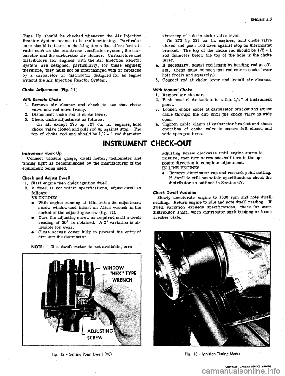
• With engine running at idle, raise the adjustment
screw window-and insert an Allen wrench in the
socket of the adjusting screw (fig. 12).
• Turn the adjusting screw as required until a dwell
reading of 30° is obtained. A 2° variation is al-
lowable for wear.
• Close access cover fully to prevent the entry of
dirt into the distributor.
NOTE: If a dwell meter is not available, turn
adjusting screw clockwise until engine starts to
misfire, then turn screw one-half turn in the op-
posite direction to complete adjustment.
IN LINE ENGINES
• Remove distributor cap and recheck point setting.
If dwell is still not within specifications check the
distributor as outlined in Section 6Y.
Check Dwell Variation
Slowly accelerate engine to 1500 rpm and note dwell
reading. Return engine to idle and note dwell reading. If
dwell variation exceeds specifications, check for worn
distributor shaft, worn distributor shaft bushing or loose
breaker plate.
WINDOW
"HEX" TYPE
WRENCH
Fig.
12 - Setting Point Dwell (V8)
Fig.
13 - Ignition Timing Marks
CHEVROLET CHASSIS SERVICE MANUAL
Page 273 of 659
ENGINE
6-8
Check
and
Adjust Ignition Timing
(Fig. 13)
1.
Disconnect
the
distributor spark advance hose
and
plug
the
vacuum source opening.
2.
Start engine
and run at
idle speed
(see
tune
up
chart).
3.
Aim
timing light
at
timing
tab.
NOTE:
- The
markings
on the
tabs
are in 2°
increments
(the
greatest number
of
markings
on
the
"A"
side
of the "O"). the "O"
markings
is
TDC
of
#1 cylinder
and all
BTDC settings fall
on
the
"A"
(advance) side
of "O".
4.
Adjust
the
timing
by
loosening
the
distributor clamp
and
,
rotating
the
distributor body
as
required, then
tighten
the
clamp.
5.
Stop engine
and
remove timing light
and
reconnect
the spark advance hose.
Adjust Idle Speed
and
Mixture
(Fig. 14)
(Except when
equipped with
Air
Injection Reactor System)
1.
As a
preliminary adjustment, turn idle mixture
screws lightly
to
seat
and
back
out 2
turns.
CAUTION:
Do not
turn idle mixture screw
tightly against seat
or
damage
may
result.
2.
With engine running
at
operating temperature (choke
wide open) adjust idle speed screw
to
bring idle
speed
to
specified
rpm
(automatic transmission
in
drive, manual transmission
in
neutral).
3.
Adjust idle mixture screw
to
obtain highest steady
idle speed
(1/4
turn
out
from lean roll).
4.
Repeat Steps
2 and 3 as
needed
for
final adjustment.
5.
Shut down
the
engine, remove gauges
and
install
air
cleaner.
Adjust Idle Speed
and
Mixture
(Fig. 14)
(With
Air
Injection Reactor System)
The recommended adjustment procedure
for Air
Injec-
tion Reactor System equipped engines
is as
follows:
1.
As a
preliminary adjustment, turn idle mixture
screws lightly
to
seat
and
than back
out 3
turns.
CAUTION:
Do not
turn idle mixture screw
tightly against seat
or
damage
may
result.
2.
With engine running
at
operating temperature, choke
wide open,
and
parking brake applied, adjust idle
specified idle speed (automatic
"drive"-manual transmission
in
to
in
screw
transmission
"neutral").
;3.
Adjust idle mixture screw (turn
in) to
"lean roll"
position; then turn screw
out 1/4
turn
(1/4
turn rich
from "lean roll").
The
definition
of
"lean roll" point
is
a 20 to 30 rpm
drop
in
engine speed, obtained
by
leaning
the
idle mixture.
4.
Repeat Steps
2 and 3 as
needed
for
final adjustments.
ADDITIONAL CHECKS
AND
ADJUSTMENTS
Testing Crankcase Ventilation Valve
(Fig. 15) 0
1.
Connect tachometer
and
vacuum gauge
as for
idle
speed
and
mixture adjustment.
2.
Set
parking brake, start engine
and
adjust idle speed
and mixture.
3.
Disconnect ventilation hose
at
valve, block opening
of
valve
and
read engine
rpm
change.
4.
A
change
of
less than
50 rpm
indicates
a
plugged
ventilation valve
-
replace
the
valve.
Cylinder Balance Test
(Fig. 16)
It
is
often difficult
to
locate
a
weak cylinder.
A com-
pression test,
for
example, will
not
locate
a
leaky intake
manifold,
a
valve
not
opening properly
due to a
worn
camshaft,
or a
defective spark plug.
With
the
cylinder balance test,
the
power output
of one
cylinder
may be
checked against another, using
a set of
grounding leads. When
the
power output
of
each cylinder
is
not
equal,
the
engine will lose power
and run
roughly.
Perform
a
cylinder balance test
as
follows:
1.
Connect
the
tachometer
and
vacuum gauge.
2.
Start engine
and run at 1500 rpm.
3.
Ground large clip
of
grounding leads
and
connect
in-
dividual leads
to all
spark plugs except
the
pair being
tested.
Divide
the
firing order
in
half
and
arrange
one
half
over
the
other.
The
cylinders
to be
tested together
ap-
pear
one
over
the
other.
L4 Firing Order
V8 Firing Order
1-8-4-3-6-5-7-2
1-6, 8-5, 4-7, 3-2
1-3-4-2
= 1-3
4-2
L6 Firing Order
1-5-3-6-2-4
=
=
1-4. 3-2
1-5-3
6-2-4
1-6, 5-2, 3-4
1-8-4-3
6-5-7-2
4.
Operate engine
on
each pair
of
cylinders
in
turn
and
note engine
rpm and
manifold vacuum
for
each pair.
A variation
of
more than
1
inch
of
vacuum
or 40 rpm
between pairs
of
cylinders being tested indicates that
the cylinders
are off
balance.
Battery
The battery should
be
checked with special testing
equipment
and to the
equipment manufacturers specifica-
tions.
See
Section 6Y
for
complete information
on
battery
tests.
Ignition
The following additional ignition checks
may be
made
with
any of
several pieces
of
equipment available
for un-
covering
the
source
of
engine difficulties.
The
specific
operating instructions
of the
equipment manufacturer
should
be
followed:
Cranking voltage
Ignition switch
Distributor resistance
Secondary resistance
Ignition output
and
secondary leakage
Cranking Voltage
(Fig. 17)
1.
Disconnect coil primary lead
at the
coil negative
terminal
to
prevent engine from firing during
cranking.
2.
Connect voltmeter between primary terminal
of coi|
(resistance wire side)
and
ground.
3.
Operate starting motor.
CHEVROLET CHASSIS SERVICE MANUAL
Page 281 of 659
ENGINE 6-16
5.
Adjust ignition timing and carburetor idle speed and
mixture.
VALVE STEM OIL SEAL AND/OR VALVE SPRING
Replacement
1.
Remove rocker arm cover as outlined.
2.
Remove spark plug, rocker arm and push rod on the
cylinder(s) to be serviced.
3.
Apply compressed air to the spark plug hole to hold
the valves in place.
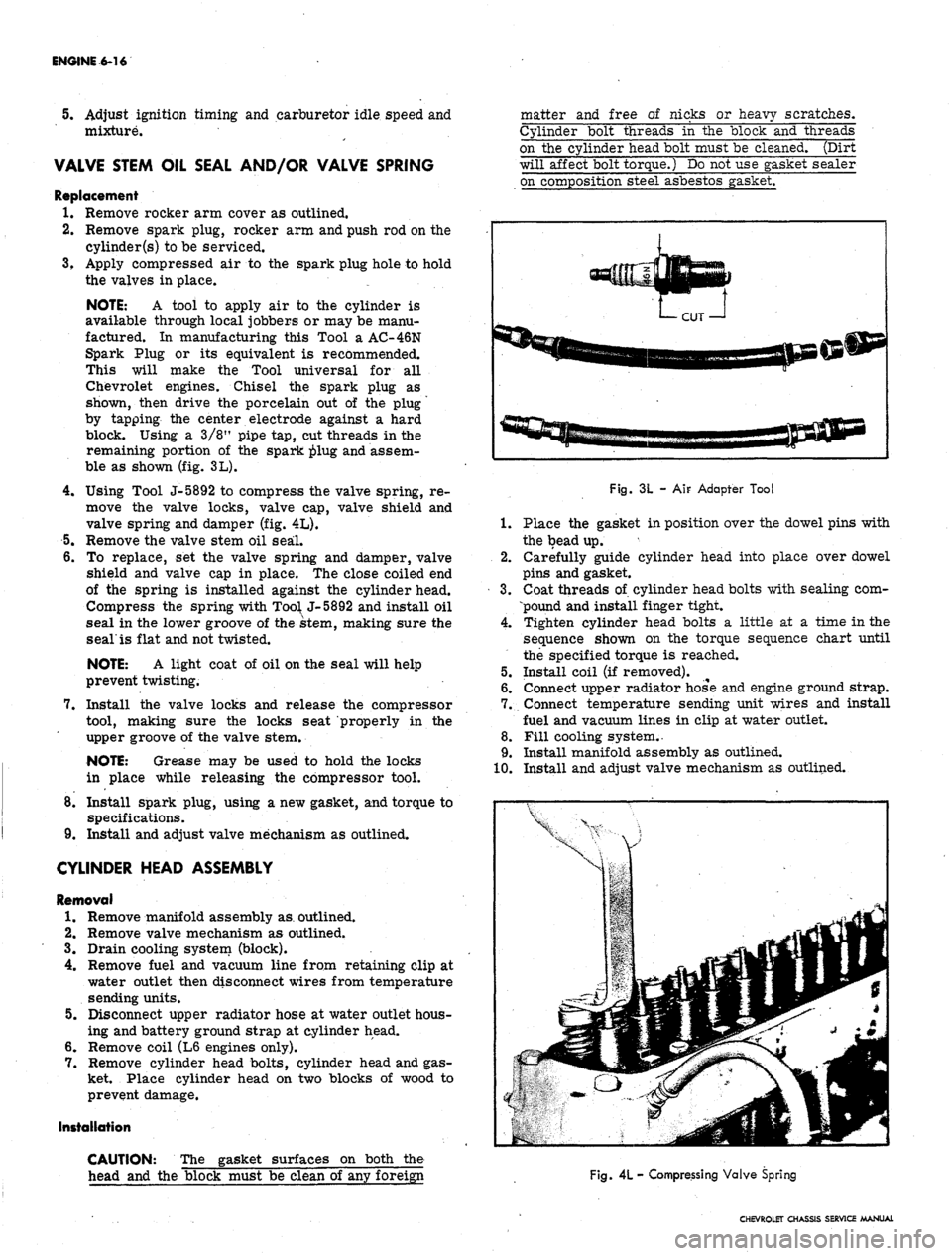
NOTE: A tool to apply air to the cylinder is
available through local jobbers or may be manu-
factured. In manufacturing this Tool a AC-46N
Spark Plug or its equivalent is recommended.
This will make the Tool universal for all
Chevrolet engines. Chisel the spark plug as
shown, then drive the porcelain out of the plug
by tapping the center electrode against a hard
block. Using a 3/8" pipe tap, cut threads in the
remaining portion of the spark ^>lug and assem-
ble as shown (fig. 3L).
4.
Using Tool J-5892 to compress the valve spring, re-
move the valve locks, valve cap, valve shield and
valve spring and damper (fig. 4L).
5.
Remove the valve stem oil seal.
6. To replace, set the valve spring and damper, valve
shield and valve cap in place. The close coiled end
of the spring is installed against the cylinder head.
Compress the spring with
Too^
J-5892 and install oil
seal in the lower groove of the stem, making sure the
seal'is flat and not twisted.
NOTE: A light coat of oil on the seal will help
prevent twisting.
7.
Install the valve locks and release the compressor
tool, making sure the locks seat properly in the
upper groove of the valve stem.
NOTE: Grease may be used to hold the locks
in place while releasing the compressor tool.
8. Install spark plug, using a new gasket, and torque to
specifications.
9. Install and adjust valve mechanism as outlined.
CYLINDER HEAD ASSEMBLY
Removal
1.
Remove manifold assembly as. outlined.
2.
Remove valve mechanism as outlined.
3.
Drain cooling system (block).
4.
Remove fuel and vacuum line from retaining clip at
water outlet then disconnect wires from temperature
sending units.
5.
Disconnect upper radiator hose at water outlet hous-
ing and battery ground strap at cylinder head.
6. Remove coil (L6 engines only).
7.
Remove cylinder head bolts, cylinder head and gas-
ket. Place cylinder head on two blocks of wood to
prevent damage.
Installation
CAUTION: The gasket surfaces on both the
head and the block must be clean of any foreign
matter and free of nicks or heavy scratches.
Cylinder bolt threads in the block and threads
on the cylinder head bolt must be cleaned. (Dirt
will affect bolt torque.) Do not use gasket sealer
on composition steel asbestos gasket.
Fig. 3L -
AIF
Adapter Tool
1.
Place the gasket in position over the dowel pins with
the bead up.
2.
Carefully guide cylinder head into place over dowel
pins and gasket.
3.
Coat threads of cylinder head bolts with sealing com-
pound and install finger tight.
4.
Tighten cylinder head bolts a little at a time in the
sequence shown on the torque sequence chart until
the specified torque is reached.
5.
Install coil (if removed).
6. Connect upper radiator hose and engine ground strap.
7.
Connect temperature sending unit wires and install
fuel and vacuum lines in clip at water outlet.
8. Fill cooling system.
•
9. Install manifold assembly as outlined.
10.
Install and adjust valve mechanism as outlined.
Fig.
4L
- Compressing Valve Spring
CHEVROLET CHASSIS SERVICE MANUAL
Page 284 of 659
ENGINE 6-19
OIL SEAL (REAR MAIN)
Replacement
The rear main bearing oil seal can be replaced (both
halves) without removal of the crankshaft.
NOTE:
Always replace the upper and lower
seal as a unit. Install with the lip facing toward
the front of the engine.
1.
With the oil pan removed, remove the rear main
bearing cap.
2.
Remove oil seal from the groove by lifting the end
tab (fig. 7L) then clean seal groove.
3.
Lubricate the lip and O.D. of a new seal with engine
oil. Keep oil off the parting line surface. Insert
seal in cap and roll it into place with finger and
thumb,
using light pressure so beads on seal O.D.
are not cut by seal groove at cap parting line. Be
sure tabs on seal are properly located in cross
grooves.
4.
To remove the upper half of the seal, use a small
hammer to tap a brass pin punch on one end of seal
until it protrudes far enough to be removed with
pliers (fig. 8L).
NOTE:
Always clean crankshaft surface re-
moving all foreign deposits before installing a
new seal. Also clean seal groove.
5. Lubricate the lip and O.D. of a new seal with engine
oil. Keep oil off the parting line surface. Gradually
push with a hammer handle, while turning crank-
shaft, until seal is rolled into place. (Similar to in-
stalling a main bearing.) Be careful that seal bead
on O.D. is not cut. Compress seal towards crank-
shaft as much as possible.
6. Install the rear main bearing cap (with new seal) and
torque to specifications. Be sure cross seal tabs
are in place and properly seated.
CRANKSHAFT PULLEY AND HUB
(Chevy II with L4 Engine)
Removal
1.
Drain radiator and disconnect upper and lower radi-
ator hoses at radiator.
2.
Remove radiator core as outlined in Section 13.
3.
Remove fan belt. Remove crankshaft pulley from
pulley hub.
4.
Install puller Tool J-6978 to pulley hub with two
3/8"
x 2" and one 5/16" x 2" bolts and remove hub
then remove puller tool.
Installation
1.
Coat oil seal contact area on hub with engine oil
position hub over crankshaft and key and start hub
into position with a mallet. Using Tool J-5590 drive
onto crankshaft until it bottoms against crankshaft
gear.
NOTE:
Crankshaft extends slightly through hub
and a tool is necessary to drive hub completely
into bottomed position.
2.
Install pulley onto hub.
NOTE:
There are two 3/8" holes and one
5/16" hole that must be matched on hub in order
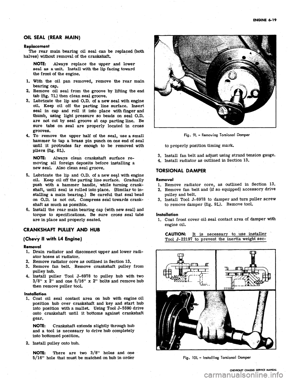
Fig.
9L - Removing Torsional Damper
to properly position timing mark.
3.
Install fan belt and adjust using strand tension gauge.
4.
Install radiator as outlined in Section 13.
TORSIONAL DAMPER
Removal
1.
Remove radiator core, as outlined in Section 13.
2.
Remove fan belt and (if so equipped) accessory drive
pulley and belt.
3.
Install Tool J-6978 to damper and turn puller screw
to remove damper (fig. 9L). Remove tool.
Installation
1.
Coat front cover oil seal contact area of damper with
engine oil.
CAUTION: It is necessary to use installer
Tool J-22197 to prevent the inertia weight sec-
Fig.
10L - Installing Torsional Damper
CHEVROLET CHASSIS SERVICE MANUAL
Page 294 of 659
ENGINE 6-29
an extent that the return spring can no longer push
the plunger back up to working position. Probable
causes are:
a. Excessive varnish or carbon deposit causing ab-
normal stickiness.
b.
(Sailing or "pick-up" between plunger and bore of
lifter body, usually caused by an abrasive piece of
dirt or metal wedging between plunger and lifter
body.
2.
Moderate Rapping Noise--Probable causes are:
a. Excessively high leakdown rate.
b.
Leaky check valve seat.
c. Improper adjustment.
3.
General Noise Throughout the Valve Train-rThis
will, in almost all cases, be a definite indication of
insufficient oil supply, or improper adjustment.
4.
Intermittent Clicking—Probable causes are:
a. A microscopic piece of dirt momentarily caught
between ball seat and check valve ball.
b.
In rare cases, the ball itself may be out-of-round
or have a flat spot.
c. Improper adjustment.
In most cases where noise exists in one or more lifters
all lifter units should be removed, disassembled, cleaned
in a solvent, reassembled, and reinstalled in the engine.
If dirt, corrosion, carbon, etc. is shown to exist in one
unit, it more than likely exists in all the units, thus it
would only be a matter of time before all lifters caused
trouble.
Removal
1.
Remove intake manifold as outlined.
2.
Remove valve mechanism as outlined.
3.
Remove valve lifters.
NOTE: Place valve lifters in a rack so they
may be reinstalled in the same location.
Installation
1.
Install valve lifters.
NOTE: Whenever new valve lifters are being
installed coat foot of valve lifters with Molykote
or its equivalent.
2.
Install intake manifold as outlined.
3.
Install and adjust valve mechanism as outlined.
VALVE STEM OIL SEAL AND/OR VALVE SPRING
Replacement
1.
Remove rocker arm cover(s) as outlined.
2.
Remove spark plug, rocker arm and push rod on the
cylinders to be serviced.
3.
Apply compressed air to the spark plug hole to hold
tl*e valves in place.
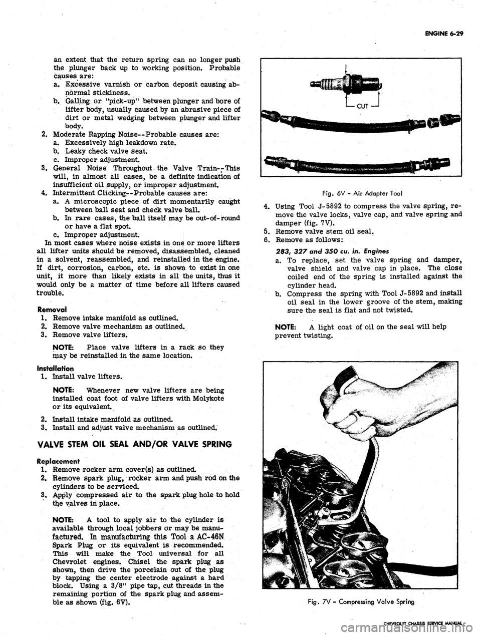
NOTE: A tool to apply air to the cylinder is
available through local jobbers or may be manu-
factured. In manufacturing this Tool a AC-46N
Spark Plug or its equivalent is recommended.
This will make the Tool universal for all
Chevrolet engines. Chisel the spark plug as
shown, then drive the porcelain out of the plug
by tapping the center electrode against a hard
block. Using a 3/8" pipe tap, cut threads in the
remaining portion of the spark plug and assem-
ble as shown (fig. 6V).
Fig.
6V - Air Adapter Tool
4.
Using Tool J-5892, to compress the valve spring, re-
move the valve locks, valve cap, and valve spring and
damper (fig. 7V).
5.
Remove valve stem oil seal.
6. Remove as follows:
283, 327 and 350 eu. in.
Engines
a. To replace, set the valve spring and damper,
valve shield and valve cap in place. The close
coiled end of the spring is installed against the
cylinder head.
b.
Compress the spring with Tool J-5892 and install
oil seal in the lower groove of the stem, making
sure the seal is flat and not twisted.
NOTE: A light coat of oil on the seal will help
prevent twisting.
Fig.
7V - Compressing Valve Spring
CHEVROLET CHASSIS SERVICE MANUAL
Page 297 of 659
ENGINE 6-32
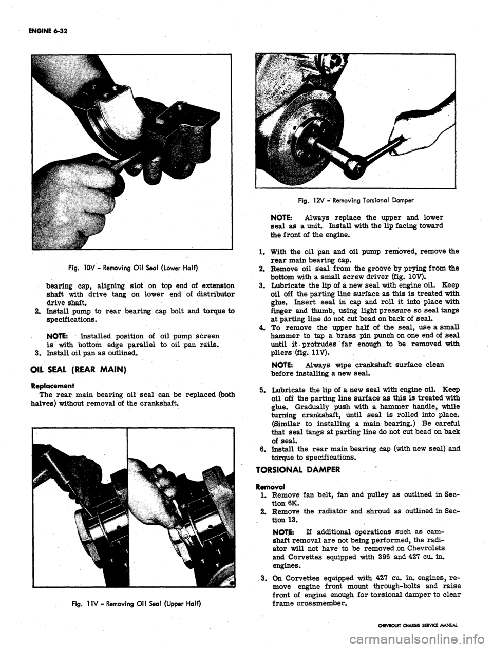
Fig.
1GV - Removing Oil Seal (Lower Half)
bearing cap, aligning slot on top end of extension
shaft with drive tang on lower end of distributor
drive shaft.
2.
Install pump to rear bearing cap bolt and torque to
specifications.
NOTE:
Installed position of oil pump, screen
is with bottom edge parallel to oil pan rails.
3.
Install oil pan as outlined.
OIL SEAL (REAR MAIN)
Replacement
The rear main bearing oil seal can be replaced (both
halves) without removal of the crankshaft.
Fig.
12V - Removing Torstonal Damper
NOTE:
Always replace the upper and lower
seal as a unit.. Install with the lip facing toward
the front of the engine.
With the oil pan and oil pump removed, remove the
rear main bearing cap.
Remove oil seal from the groove by prying from the
bottom with a small screw driver (fig. 10V).
Lubricate the lip of a new seal with engine oil. Keep
oil off the parting line surface as this is treated with
glue. Insert seal in cap and roll it into place with
finger and thumb, using light pressure so seal tangs
at parting line do not cut bead on back of seal.
To remove the upper half of the seal, use a small
hammer to tap a brass pin punch on one end of seal
until it protrudes far enough to be removed with
pliers (fig. 11V).
NOTE:
Always wipe crankshaft surface clean
before installing a new seal.
1.
2.
3.
5.
Fig.
1IV - Removing Oil Seal (Upper Half)
Lubricate the lip of a new seal with engine oil. Keep
oil off the parting line surface as this is treated with
glue. Gradually push with a. hammer handle, while
turning crankshaft, until seal is rolled into place.
(Similar to installing a main bearing.) Be careful
that seal tangs at parting line do not cut bead on back
of seal.
6. Install the rear main bearing cap (with new seal) and
torque to specifications.
TORSIONAL DAMPER
Removal
1.
Remove fan belt, fan and pulley as outlined in Sec-
tion 6K.
2.
Remove the radiator and shroud as outlined in Sec-
tion 13.
NOTE:
If additional operations such as cam-
shaft removal are not being performed, the radi-
ator will not have to be removed
.on
Chevrolets
and Corvettes equipped with 396 and 427 cu. in.
engines.
. 3. On Corvettes equipped with 427 cu. in. engines, re-
move engine front mount through-bolts and raise
front of engine enough for torsional damper to clear
frame crossmember.
CHEVROLET CHASSIS SERVICE MANUAL
Page 300 of 659
ENGINE 6-35
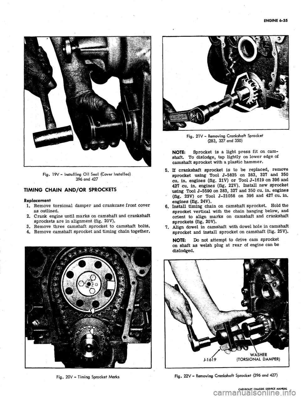
Fig.
19V - installing Oil Seal (Cover Installed)
396 and 427
TIMING CHAIN AND/OR SPROCKETS
Replacement
1.
Remove torsionai damper and crankcase front cover
as outlined.
2.
Crank engine until marks on camshaft and crankshaft
sprockets are in alignment (fig. 20V).
3.
Remove three camshaft sprocket to camshaft boltg.
4.
Remove camshaft sprocket and timing chain together.
Fig.
21V - Removing Crankshaft Sprocket
(283,
327 and 350)
NOTE: Sprocket is a light press fit on cam-
shaft. To dislodge, tap lightly on lower edge of
camshaft sprocket with a plastic hammer.
5.
If crankshaft sprocket is to be replaced, remove
sprocket using Tool J-5825 on 283, 327 and 350
cu. in. engines (fig. 21V) or Tool J-1619 on 396 and
427 cu. in. engines (fig. 22V). Install new sprocket
using Tool J-5590 on 283, 327 and 350 cu. in. engines
- (fig. 23V) or Tool J-21058 on 396 and 427 cu. in.
engines (fig. 24V).
6. Install timing chain on camshaft sprocket. Hold the
sprocket vertical with the chain hanging below, and
orient to align marks on camshaft and crankshaft
sprockets (fig. 20V).
7.
Align dowel in camshaft with dowel hole in camshaft
sprocket and install sprocket on camshaft (fig. 25V).
NOTE: Do not attempt to drive cam sprocket
on shaft as welsh plug at rear of engine can be
dislodged.
WASHER
(TORSIONAL DAMPER)
Fig.
20V - Timing Sprocket Marks
Fig.
22V - Removing Crankshaft Sprocket (396 and 427)
CHEVROLET CHASSIS SERVICE MANUAL
Page 302 of 659
ENGINE 6-37
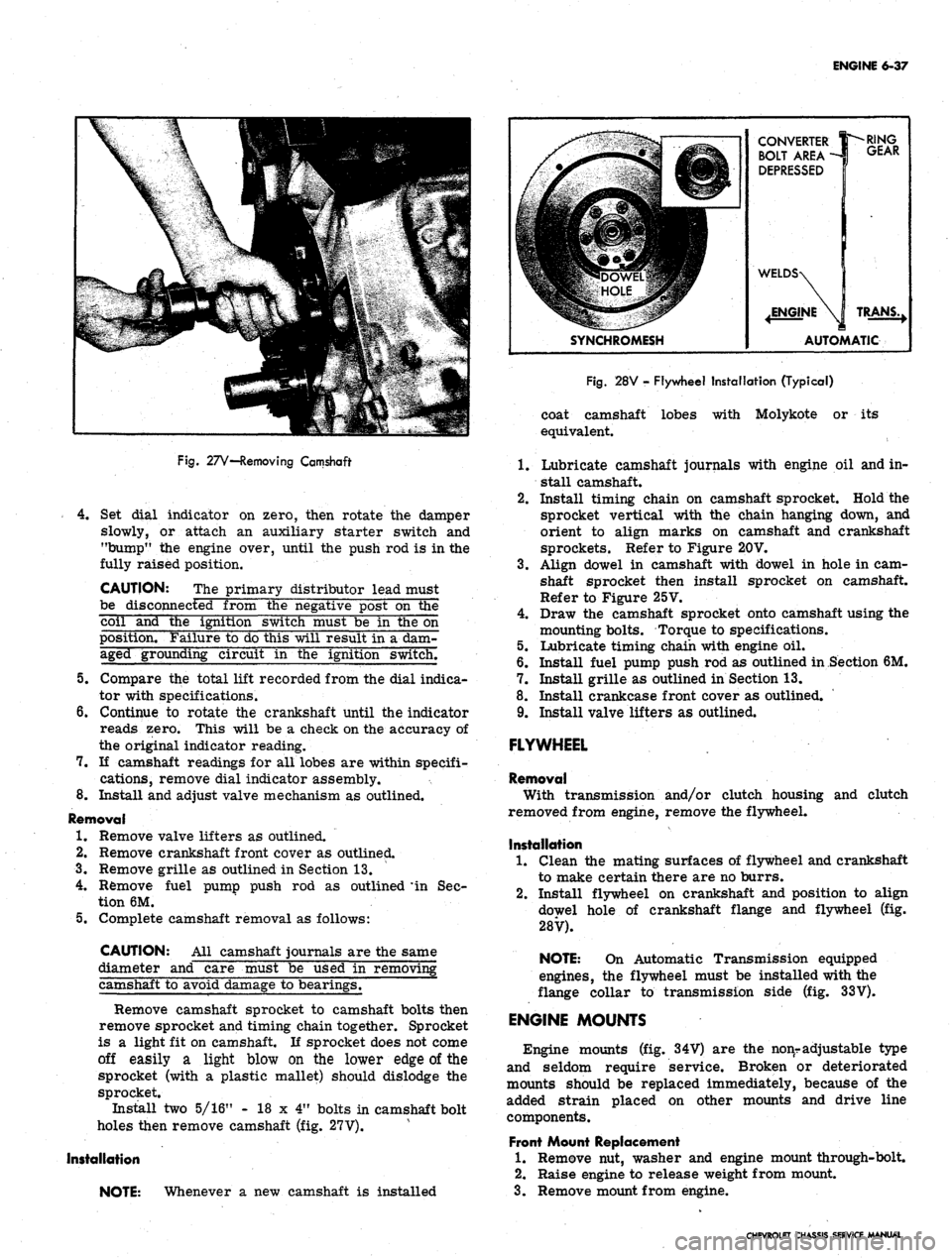
Fig.
27V—Removing Camshaft
4.
Set dial indicator on zero, then rotate the damper
slowly, or attach an auxiliary starter switch and
"bump" the engine over, until the push rod is in the
fully raised position.
CAUTION: The primary distributor lead must
be disconnected from the negative post on the
coil and the ignition switch must be in the on
position. Failure to do this will result in a dam-
aged grounding circuit in the ignition switch.
5.
Compare the total lift recorded from the dial indica-
tor with specifications.
6. Continue to rotate the crankshaft until the indicator
reads zero. This will be a check on the accuracy of
the original indicator reading.
7.
If camshaft readings for all lobes are within specifi-
cations, remove dial indicator assembly.
8. Install and adjust valve mechanism as outlined.
Removal
1.
Remove valve lifters as outlined.
2.
Remove crankshaft front cover as outlined.
3.
Remove grille as outlined in Section 13.
4.
Remove fuel pump push rod as outlined * in Sec-
tion 6M.
5.
Complete camshaft removal as follows:
CAUTION: All camshaft journals are the same
diameter and care must be used in removing
camshaft to avoid damage to bearings.
Remove camshaft sprocket to camshaft bolts then
remove sprocket and timing chain together. Sprocket
is a light fit on camshaft. If sprocket does not come
off easily a light blow on the lower edge of the
sprocket (with a plastic mallet) should dislodge the
sprocket.
Install two 5/16" - 18 x 4" bolts in camshaft bolt
holes then remove camshaft (fig. 27V).
Installation
NOTE: Whenever a new camshaft is installed
CONVERTER
BOLT AREA -
DEPRESSED
SYNCHROMESH
RING
GEAR
TRANS.,
AUTOMATIC
Fig.
28V - Flywheel Installation (Typical)
coat camshaft lobes with Molykote or its
equivalent.
1.
Lubricate camshaft journals with engine oil and in-
stall camshaft.
2.
Install timing chain on camshaft sprocket. Hold the
sprocket vertical with the chain hanging down, and
orient to align marks on camshaft and crankshaft
sprockets. Refer to Figure 20V.
3.
Align dowel in camshaft with dowel in hole in cam-
shaft sprocket then install sprocket on camshaft.
Refer to Figure 25V.
4.
Draw the camshaft sprocket onto camshaft using the
mounting bolts. Torque to specifications.
5.
Lubricate timing chain with engine oil.
6. Install fuel pump push rod as outlined in Section 6M.
7.
Install grille as outlined in Section 13.
8. Install crankcase front cover as outlined.
9. Install valve lifters as outlined.
FLYWHEEL
Removal
With transmission and/or clutch housing and clutch
removed from engine, remove the flywheel.
Installation
1.
Clean the mating surfaces of flywheel and crankshaft
to make certain there are no burrs.
2.
Install flywheel on crankshaft and position to align
dowel hole of crankshaft flange and flywheel (fig.
28V).
NOTE: On Automatic Transmission equipped
engines, the flywheel must be installed with the
flange collar to transmission side (fig. 33V).
ENGINE MOUNTS
Engine mounts (fig. 34V) are the nonr adjustable type
and seldom require service. Broken or deteriorated
mounts should be replaced immediately, because of the
added strain placed on other mounts and drive line
components.
Front Mount Replacement
1.
Remove nut, washer and engine mount through-bolt.
2.
Raise engine to release weight from mount.
3.
Remove mount from engine.
CHEVROLET CHASSIS SERVICE MANUAL
Page 309 of 659

SECTION 6M
ENGINE FUEL
CONTENTS OF THIS SECTION
Page
Carburetors 6M-1 Fuel Pumps .
Air Cleaners 6M-7 Special Tools
Page
6M-10
6M-12
CARBURETORS
INDEX
Page
General Description 6M-1
Service Procedures 6M-1
Preliminary Checks 6M-1
Idle Speed and Mixture Adjustment ........... 6M-1
Fast Idle Adjustment .................. 6M-3
Choke Adjustment 6M-3
Float Adjustment 6M-4
Page
Additional Adjustments 6M-4
Removal 6M-4
Test Before Installation 6M-5
Installation 6M-5
Fuel Filter Maintenance 6M-5
Choke Coil Replacement 6M-5
Throttle Linkage Adjustment . . 6M-6
GENERAL DESCRIPTION
Various carburetors (fig. lc) are used with Chevrolet,
Chevelle, Chevy II, Camaro and Corvette passenger
vehicles. These carburetors are designed to meet the
particular requirements of engines, transmissions and
vehicles, therefore carburetors that look alike are not
always interchangeable. (Refer to carburetor part num-
ber and/or specifications.)
Because many service procedures for the various
carburetors are similar, typical illustrations and pro-
cedures are used except where specific illustrations or
procedures are necessary to clarify the operation.
This section covers removal, installation and adjust-
ments (on engine) of carburetors. Also covered in this
section are maintenance procedures for choke coils,
throttle linkage and fuel filters. For carburetor .over-
haul procedures and additional adjustments (bench), re-
fer to Section 6M of the Overhaul Manual under the
carburetor being serviced.
Specifications for carburetors are located in the back
of this manual.
SERVICE PROCEDURES
Preliminary Checks
1.
Thoroughly warm-up engine. If the engine is cold,
allow to run for at least 15 minutes.
2.
Inspect torque of carburetor to intake manifold bolts
and intake manifold to cylinder head bolts to exclude
the possibility of air leaks.
3.
Inspect manifold heat control valve (if used) for free-
dom of action and correct spring tension.
Idle Speed and Mixture Adjustment (Except Air Injection
Reactor System)
NOTE:
This adjustment should be performed
with engine at operating temperature and park-
ing brake applied.
1.
Remove Air Cleaner.
2.
Connect tachometer and vacuum gauge to engine, then
set hand brake and shift transmission into neutral.
3.
As a preliminary adjustment, turn idle mixture
screws lightly to seat and back out 1-1/2 turns.
CAUTION: Do not turn idle mixture screw
tightly against seat or damage may result.
4.
With engine running (choke wide open) adjust idle
speed screw to specified idle speed, (automatic
transmission in drive, synchronized transmission in
neutral).
5. Adjust idle mixture screw to obtain highest steady
vacuum at specified idle speed.
NOTE:
On air conditioned vehicles, turn air
conditioning to the "on" position and hold the
hot idle compensator valve closed while adjust-
ing idle speed and idle mixture screws.
NOTE:
On Rochester BV carburetors the idle
mixture screw should be turned out 1/4 turn
from the "lean roll" position. The definition
of "lean roll" point is a 20 to 30 rpm drop
in engine speed obtained by leaning the idle
mixture.
6. Repeat Steps 4 and5 as needed for final adjustment.
NOTE:
If necessary, final adjustment of the \
carburetor may be made with the air cleaner
installed.
7. Turn engine off, remove gauges and install air
clearer.
CHEVROLET CHASSIS SERVICE MANUAL
Page 311 of 659

ENGINE FUEL 6M-3
Idle Speed and Mixture Adjustment (With Air Injection
Reactor System)
The following is the recommended procedure for Air
Injection Reactor System equipped engines.
NOTE: This adjustment should be performed
with engine at operating temperature and parking
brake applied.
1.
Remove air cleaner.
2.
Connect tachometer to engine, then set hand brake
and shift transmission into neutral.
3.
As a preliminary adjustment, turn idle mixture
screws lightly to seat and back out 3 turns.
CAUTION: Do not turn idle mixture screw
tightly against seat or damage may result."
4.
With engine running (choke wide open) adjust idle
speed screw to specified idle speed. (Automatic
transmission in dirve, synchronized transmission in
neutral).
5.
Adjust idle mixture screw (turn in) to "lean roll"
position; then turn screw out 1/4 turn (1/4 turn
rich from "lean roll"). The definition of "lean
roll" point is a 20 to 30 rpm drop in engine speed,
obtained by leaning the idle mixture.
NOTE: On air conditioned vehicles, turn air
conditioning "OFF" on in-line, 283, 327, and'
350 cu. in. engines, and turned "ON" and hot
idle compensator held closed on 396 and 427 cu.
in. engines.
6. Repeat Steps 4 and 5 as needed for final adjustment.
NOTE: If necessary, final adjustment of the
carburetor may be made with air cleaner
installed.
7.
Shut down the engine, remove gauges and install air
cleaner. *
Fast Idle Adjustment
Rochester
4MV and Holley
With fast idle lever on high step of cam and choke valve
open (engine warm) set fast idle to give specified engine
rpm. Adjust sejrew on Rochester 4MV and bend fast
idle lever *pn Holley. .
Choke Adjustment
With Remote Choke (Fig. 2c)
1.
Remove air cleaner and check to see that choke
valve and rod move freely.
2.
Disconnect choke rod at choke lever.
3.
Check choke adjustment as follows:
On all except 275 and 300 h.p. 327 cu. in. engines,
hold choke valve closed and pull.rod up against stop.
The top of choke rod end should be 1/2-1 rod diame-
ter above top of hole in choke valve lever.
On 275 and 300 h.p. 327 cu. in. engines, hold choke
valve closed and push rod down against stop on ther-
mostat bracket. The top of the choke rod should be
1/2-1 rod diameter below the top of the hole in the
choke lever.
4.
If necessary, adjust rod length by bending rod at
offset bend. (Bend must be such that rod enters
choke lever hole freely and squarely).
5.
Connect rod at choke lever and install air cleaner.
With Manual Choke (Carter YF)
1.
Remove air cleaner.
CHOKE VALVE
COMPLETELY
CLOSED
PULL UPWARD ON
ROD TO END OF
TRAVEL
BEND ROD
TO ADJUST
ROD IN BOTTOM
OF SLOT
BOTTOM OF
ROD SHOULD
BE EVEN WITH
TOP OF
HOLE
CHOKE VALVE
CLOSED
BOTTOM OF
ROD SHOULD
BE EVEN WITH
TOP OF HOLE
TOP OF ROD
SHOULD BE EVEN
WITH BOTTOM
OF HOLE (CHOKE
CLOSED)
BEND ROD TO
ADJUST
PULL DOWNWARD'
ON ROD TO CON-
TACT STOP
L6 (TYPICAL)
[
V8 327-275 HP
V8 350-295 HP
BEND ROD
TO ADJUST
PULL UPWARD ON
ROD TO CONTACT
STOP ON BRACKET
ALL V8 (EXCEPT 327-275 HP
AND 350-295 HP)
Fig.
2C—Remote Choke Adjustment
CHEVROLET CHASSIS SERVICE MANUAL