light CHEVROLET CAMARO 1967 1.G Chassis Manual PDF
[x] Cancel search | Manufacturer: CHEVROLET, Model Year: 1967, Model line: CAMARO, Model: CHEVROLET CAMARO 1967 1.GPages: 659, PDF Size: 114.24 MB
Page 340 of 659

ENGINE-ELECTRICAL 6Y-15
L
RELAY
TERMINAL "F" TERMINAL
"BAT" \ ' /
TERMINAL
/ / /
GRD7
TERMINAL
5.5" SERIES ID DELCOTRON
"BAH"
TERMINAL
^Vs^^^^lijBii^^8C^3^SH|j^^^^^^sH^^Bf- y/
RELAY ^^^"^^^jWwIi^^^^ RELAY
6.2" SERIES 2D, TYPE 150 DELCOTRON
Fig.
14c—Delcotrons - Full View
end or use Adapter J-21501 and a box wrench) on re-
taining nut, insert a 5/16" alien wrench through
socket and adapter into hex on shaft to hold the shaft
while removing the nut.
2.
Remove washer and slide pulley from shaft.
3.
To install, slide pulley and washer on shaft and start
the nut.
4.
Use the socket and adapter with a torque wrench and
tighten-nut to 50 ft. lbs. torque.
BRUSH
REPLACEMENT
6.2"
Delcotron
1.
Remove two nuts retaining the blade connectors and
remove the connectors (fig. 17c). Slide the indicator
light relay wire from the terminal post.
2.
Remove two screws retaining the capacitor and brush
holder to rear end frame, Remove brush holder.
3.
To install brushes, push brushes into holder and
install pin to keep the brushes in holder.
4.
Attach brush assembly and condenser to the end
frame with hex-head stud on the .left side only.
Fig.
15c—Pulley Removal
Fig.
16c—Torqulng Pulley Nut
CHEVROLET CHASSIS SERVICE MANUAL
Page 346 of 659
ENGINE-ELECTRICAL
6Y-21
Fig.
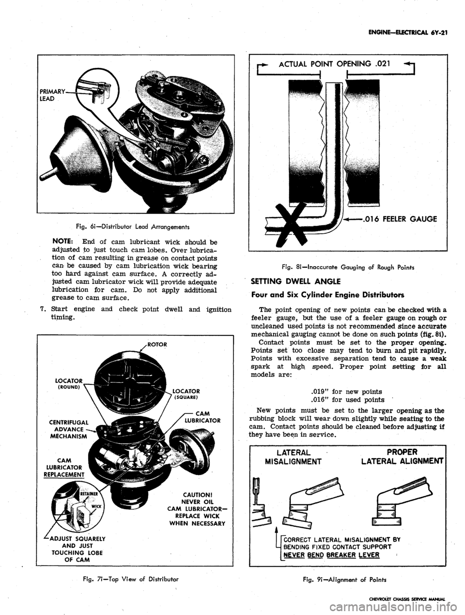
6i—Distributor Lead Arrangements
NOTE:
End of cam
lubricant wick should
be
adjusted
to
just touch
cam
lobes. Over lubrica-
tion
of cam
resulting
in
grease
on
contact points
can-
be
caused
by cam
lubrication wick bearing
too hard against
cam
surface.
A
correctly
ad-
justed
cam
lubricator wick will provide adequate
lubrication
for cam. Do not
apply additional
grease
to cam
surface.
7.
Start engine
and
check point dwell
and
ignition
timing.
ACTUAL
POINT OPENING
.021
.016
FEELER GAUGE
LOCATOR ___JH^H
(ROUND)
V~^3H|
CENTRIFUGAL
\
jdft
ADVANCE
-~-»JBlMBl
MECHANISM
«H
CAM g^k. / X
LUBRICATOR
V^^^
REPLACEMENT
^£9
^-ADJUST
SQUARELY
AND
JUST
TOUCHING
LOBE
OF
CAM
.ROTOR
I^^I^BL
LOCATOR
(PBV 7
(SQUARE)
SBSSF
/
WWjga^/
^/
LUBRICATOR
H^f
CAUTION!
S5y
NEVER
OIL
•-^
CAM
LUBRICATOR-
REPLACE
WICK
WHEN
NECESSARY
Fig.
8i—Inaccurate Gauging
of
Rough Points
SETTING DWELL ANGLE
Four
and Six
Cylinder Engine Distributors
The point opening
of new
points
can be
checked with
a
feeler gauge,
but the use of a
feeler gauge
on
rough
or
uncleaned used points
is not
recommended since accurate
mechanical gauging cannot
be
done
on
such points (fig. 8i).
Contact points must
be set to the
proper opening.
Points
set too
close
may
tend
to
burn and
pit
rapidly.
Points with excessive separation tend
to
cause
a
weak
spark
at
high speed. Proper point setting
for all
models
are:
.019"
for new
points
.016"
for
used points
New points must
be set to the
larger opening
as the
rubbing block will wear down slightly while seating
to the
cam. Contact points should
be
cleaned before adjusting
if
they have been
in
service.
LATERAL
MISALIGNMENT
PROPER
LATERAL
ALIGNMENT
pCORRECT
LATERAL MISALIGNMENT
BY
M
BENDING FIXED CONTACT SUPPORT
[NEVER
BEND BREAKER LEVER
Fig.
7i—Top View
of
Distributor
Fig.
9i—Alignment
of
Points
CHEVROLET
CHASSIS SERVICE /MANUAL
Page 347 of 659
ENGINE-ELECTRICAL 6Y-22
ADJUST DWELL
ANGLE SETTING OR
POINT OPENING
Fig.
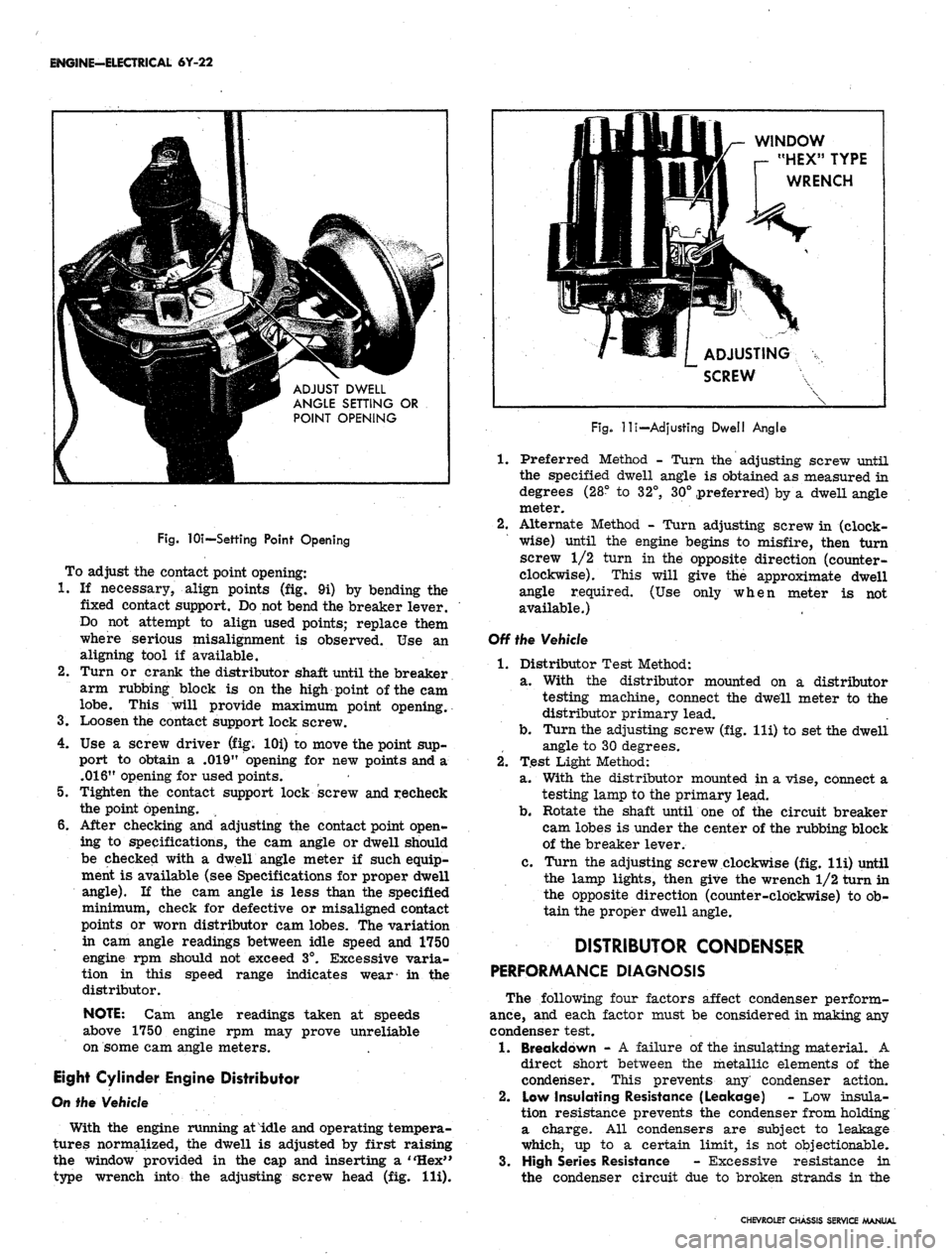
lOi—Settihg Point Opening
To adjust the contact point opening:
1.
If necessary, align points (fig. 9i) by bending the
fixed contact support. Do not bend the breaker lever.
Do not attempt to align used points; replace them
where serious misalignment is observed. Use an
aligning tool if available.
2.
Turn or crank the distributor shaft until the breaker
arm rubbing block is on the high point of the cam
lobe.
This will provide maximum point opening.
3.
Loosen the contact support lock screw.
4.
Use a screw driver (fig. lOi) to move the point sup-
port to obtain a .019" opening for new points and a
.016"
opening for used points.
5.
Tighten the contact support lock screw and recheck
the point opening.
6. After checking and adjusting the contact point open-
ing to specifications, the cam angle or dwell should
be checked with a dwell angle meter if such equip-
ment is available (see Specifications for proper dwell
angle).
If the cam angle is less than the specified
minimum, check for defective or misaligned contact
points or worn distributor cam lobes. The variation
in cam angle readings between idle speed and 1750
engine rpm should not exceed 3°. Excessive varia-
tion in this speed range indicates wear- in the
distributor.
NOTE:
Cam angle readings taken at speeds
above 1750 engine rpm may prove unreliable
on some cam angle meters.
Eight Cylinder Engine Distributor
On the Vehicle
With the engine running at idle and operating tempera-
tures normalized, the dwell is adjusted by first raising
the window provided in the cap and inserting a "Hex"
type wrench into the adjusting screw head (fig. Hi).
WINDOW
r- "HEX" TYPE
WRENCH
ADJUSTING
SCREW
Fig.
-lli—Adjusting Dwell Angle
1.
Preferred Method - Turn the adjusting screw until
the specified dwell angle is obtained as measured in
degrees (28° to 32°, 30° preferred) by a dwell angle
meter.
2.
Alternate Method - Turn adjusting screw in (clock-
wise) until the engine begins to misfire, then turn
screw 1/2 turn in the opposite direction (counter-
clockwise). This will give the approximate dwell
angle required. (Use only when meter is not
available.)
Off the Vehicle
1.
Distributor Test Method:
a. With the distributor mounted on a distributor
testing machine, connect the dwell meter to the
distributor primary lead.
b.
Turn the adjusting screw (fig. lli) to set the dwell
angle to 30 degrees.
2.
Test Light Method:
a. With the distributor mounted in a vise, connect a
testing lamp to the primary lead.
b.
Rotate the shaft until one of the circuit breaker
cam lobes is under the center of the rubbing block
of the breaker lever.
c. Turn the adjusting screw clockwise (fig. lli) until
the lamp lights, then give the wrench 1/2 turn in
the opposite direction (counter-clockwise) to ob-
tain the proper dwell angle.
DISTRIBUTOR CONDENSER
PERFORMANCE DIAGNOSIS
The following four factors affect condenser perform-
ance,
and each factor must be considered in making any
condenser test.
1.
Breakdown - A failure of the insulating material. A
direct short between the metallic elements of the
condenser. This prevents any' condenser action.
2.
Low Insulating Resistance (Leakage) - Low insula-
tion resistance prevents the condenser from holding
a charge. All condensers are subject to leakage
which, up to a certain limit, is not objectionable.
3.
High Series Resistance - Excessive resistance in
the condenser circuit due to broken strands in the
CHEVROLET CHASSIS SERVICE MANUAL
Page 351 of 659
ENGINE-ELECTRICAL 6Y-26
INSTALLATION-ENGINE NOT DISTURBED
(ALL MODELS)
1.
Turn the rotor about 1/8 turn in a clockwise direc-
tion past the mark previously placed on the distribu-
tor housing to locate rotor.
2.
Push the distributor down into position in the block
with the housing in a normal "installed" position
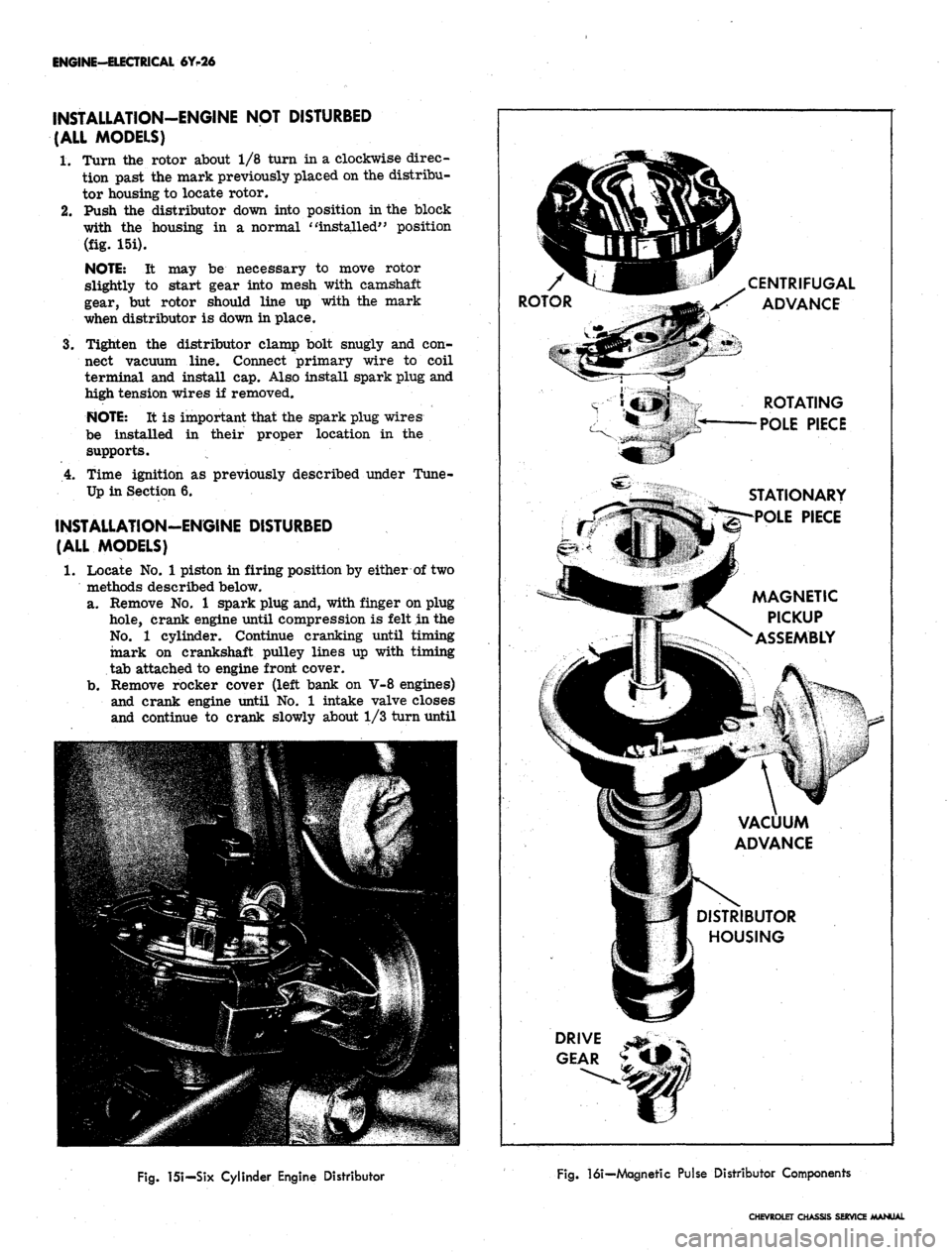
(fig. 15i).
NOTE: It may be necessary to move rotor
slightly to start gear into mesh with camshaft
gear, but rotor should line up with the mark
when distributor is down in place.
3.
Tighten the distributor clamp bolt snugly and con-
nect vacuum line. Connect primary wire to coil
terminal and install cap. Also install spark plug and
high tension wires if removed.
NOTE: It is important that the spark plug wires
be installed in their proper location in the
supports.
4.
Time ignition as previously described under Tune-
Up in Section 6.
INSTALLATION-ENGINE DISTURBED
(ALL MODELS)
1.
Locate No. 1 piston in firing position by either of two
methods described below,
a. Remove No. 1 spark plug and, with finger on plug
hole,
crank engine until compression is felt in the
No.
1 cylinder. Continue cranking until timing
mark on crankshaft pulley lines up with timing
tab attached to engine front cover.
b.
Remove rocker cover (left bank on V-8 engines)
and crank engine until No. 1 intake valve closes
and continue to crank slowly about 1/3 turn until
CENTRIFUGAL
jS ADVANCE
ROTATING
POLE PIECE
STATIONARY
POLE PIECE
MAGNETIC
PICKUP
ASSEMBLY
VACUUM
ADVANCE
DISTRIBUTOR
HOUSING
Fig.
151—Six Cylinder Engine Distributor
Fig.
16i—Magnetic Pulse Distributor Components
CHEVROLET CHASSIS SERVICE MANUAL
Page 352 of 659
ENGINE-ELECTRICAL 6Y-27
timing mark on pulley lines up with timing tab.
2.
Position distributor to opening in block in normal
installed attitude (fig. 15i), noting position of vacuum
control unit.
3.
Position rotor to point toward front of engine (with
distributor housing held in installed attitude), then
turn rotor counter-clockwise approximately 1/8 turn
more toward left cylinder bank and push distributor
down to engine camshaft. It may be necessary to ro-
tate rotor slightly until camshaft engagement is felt.
4.
While pressing firmly down on distributor housing,
kick starter over a few times to make sure oil pump
shaft is engaged. Install hold-down clamp and bolt
and snug up bolt.
5. Turn distributor body slightly until points just open
and tighten distributor clamp bolt.
6. Place distributor cap in position and check to see
that rotor lines up with terminal for No. 1 spark
plug.
7. Install cap, check all high tension wire connections
and connect spark plug wires if they have been re-
moved. It is important that the wires be installed in
their location in the supports.
NOTE:
The brackets are numbered to show the
correct installation. Wires must be installed as
indicated to prevent cross firing.
8. Connect vacuum line to distributor and distributor
primary wire to coil terminal.
9. Start engine and set timing as described under Turn-
Up in Section 6.
BREAKERLESS (MAGNETIC PULSE)
DISTRIBUTOR
REMOVAL (CORVETTE)
1.
If vehicle is equipped with radio, remove three bolts
securing ignition shield over distributor and coil.
One bolt is accessible from the top of shield, the
other two are at rear of shield, facing firewall.
2.
Disconnect tachometer drive cables from distributor
housing.
3.
Disconnect pickup coil leads at connector.
4.
Remove distributor cap.
5. Crank engine so rotor is in position to fire No. 1
cylinder and timing mark on harmonic balancer is
indexed with pointer.
6. Remove vacuum line from distributor.
7. Remove distributor clamping screw and hold-down
clamp.
8. Remove distributor and distributor-to-block gasket.
It will be noted that the rotor will rotate as the
distributor is pulled out of the block. Mark the re-
lationship of the rotor and the distributor housing
after removal so that the rotor can be set in the
same position when the distributor is being installed.
DISASSEMBLY (Fig. 16i)
NOTE:
If a distributor is being disassembled
for replacement of the stationary magnetic
pickup assembly only, it will be necessary to
perform only Steps 3, 4, 5, 7, 8, 9, and 12 of the
service procedure listed below.
1.
Remove screws securing rotor and remove rotor.
2.
Remove centrifugal weight springs and weights.
3.
Remove the tachometer drive gear from the distribu-
tor (Corvette only).
4.
Remove roll pin, then remove distributor drive gear
and washer.
CAUTION: To prevent
magnet, support drive gear
;e to the permanent
?n
driving out roll
pin.
5. Remove drive shaft assembly.
6. Remove centrifugal weight support and timer core
from drive shaft.
7. Remove connector from pickup coil leads.
8. Remove retaining ring which secures magnetic
core support plate to distributor shaft bushing in
housing.
9. As a unit, remove the entire magnetic pickup assem-
bly from the distributor housing.
10.
Remove brass washer and felt pad.
11.
Remove vacuum advance unit.
12.
To reassemble distributor, perform the above steps
in reverse order.
INSTALLATION (CORVETTE)
1.
Check to see that the engine is at firing position for
No.
1 cylinder (timing mark on harmonic balancer
indexed with pointer).
2.
Position a new distributor-to-block gasket on the
block.
3.
Before installing distributor, index rotor with hous-
ing as noted when distributor was removed. Install
distributor in block so that vacuum diaphragm faces
approximately 45° forward on the right side of the
engine and the rotor points toward contact in cap for
No.
1 cylinder.
4.
Replace distributor clamp leaving screw loose
enough to allow distributor to be turned for timing
adjustment.
5. Install spark plug wires in distributor cap. Place
wire for No. 1 cylinder in tower (marked on old cap
during disassembly) then install remaining wires
clockwise around the cap according to the firing
order (1-8-4-3-6-5-7-2).
6. Attach distributor to coil primary wires.
7. Replace distributor cap.
8. Adjust timing and then fully tighten distributor clamp
screw.
9. Attach vacuum line to distributor.
10.
Connect tachometer drive cables to distributor body.
11.
Replace ignition shields.
DISTRIBUTOR OFF-ENGINE TEST
The distributor's centrifugal and vacuum advance can
be checked in a distributor testing machine or synchro-
scope specially adapted or designed to accommodate this
type distributor. However, since this involves removing
the distributor from the engine, this test may be post-
poned until other system checks have been made. A dwell
reading cannot be obtained on this distributor and it is not
likely that the centrifugal or vacuum advance will be a
cause of trouble.
COIL REPLACEMENT
1.
Disconnect ignition switch and distributor leads from
CHEVROLET CHASSIS SERVICE MANUAL
Page 358 of 659
ENGINE-ELECTRICAL 6Y-33
O
V-8 ENGINE
STARTING MOTOR
Fig.
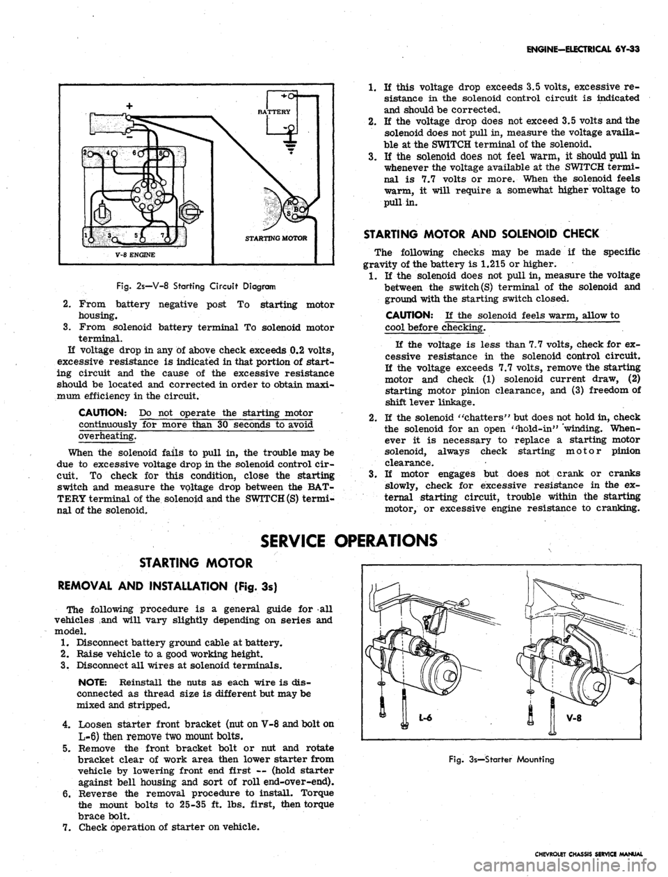
2s—V-8 Starting Circuit Diagram
2.
3.
From battery negative post
To
starting motor
housing.
From solenoid battery terminal
To
solenoid motor
terminal.
If voltage drop
in
any
of
above check exceeds 0.2 volts,
excessive resistance
is
indicated in that portion
of
start-
ing circuit
and the
cause
of the
excessive resistance
should
be
located
and
corrected
in
order to obtain maxi-
mum efficiency in the circuit.
CAUTION:
Do not
operate
the
starting motor
continuously
for
more than
30
seconds
to
avoid
overheating.
When
the
solenoid fails
to
pull
in, the
trouble may be
due
to
excessive voltage drop in the solenoid control cir-
cuit.
To
check
for
this condition, close
the
starting
switch
and
measure
the
voltage drop between
the
BAT-
TERY terminal of the solenoid and the
SWITCH (S)
termi-
nal
of
the solenoid.
1.
If
this voltage drop exceeds 3.5 volts, excessive
re-
sistance
in the
solenoid control circuit
is
indicated
and should be corrected.
2.
If the
voltage drop does not exceed 3.5 volts and the
solenoid does not pull in, measure the voltage availa-
ble
at
the SWITCH terminal
of
the solenoid.
3.
If the
solenoid does
not
feel warm,
it
should pull
in
whenever the voltage available
at
the SWITCH termi-
nal
is 7.7
volts
or
more. When
the
solenoid feels
warm,
it
will require
a
somewhat higher voltage
to
pull in.
STARTING MOTOR AND SOLENOID CHECK
The following checks
may be
made
if the
specific
gravity of the battery
is
1.215
or
higher.
1.
If the
solenoid does
not
pull in, measure the voltage
between
the
switch
(S)
terminal
of the
solenoid
and
ground with the starting switch closed.
CAUTION:
If the
solenoid feels warm, allow
to
cool before checking.
If
the
voltage
is
less than 7.7 volts, check for ex-
cessive resistance
in the
solenoid control circuit.
If
the
voltage exceeds 7.7 volts, remove the starting
motor
and
check
(1)
solenoid current draw,
(2)
starting motor pinion clearance,
and (3)
freedom of
shift lever linkage.
2.
If
the solenoid "chatters" but does not hold in, check
the solenoid
for an
open "hold-in" 'winding. When-
ever
it is
necessary
to
replace
a
starting motor
solenoid, always check starting motor pinion
clearance.
3.
If
motor engages
but
does
not
crank
or
cranks
slowly, check
for
excessive resistance
in the ex-
ternal starting circuit, trouble within
the
starting
motor,
or
excessive engine resistance
to
cranking.
SERVICE OPERATIONS
STARTING MOTOR
REMOVAL AND INSTALLATION (Fig.
3s)
The following procedure
is a
general guide
for all
vehicles
and
will vary slightly depending
on
series
and
model.
1.
Disconnect battery ground cable at battery.
2.
Raise vehicle
to a
good working height.
3.
Disconnect all wires
at
solenoid terminals.
NOTE: Reinstall
the
nuts
as
each wire
is
dis-
connected
as
thread size
is
different but may be
mixed and stripped.
4.
Loosen starter front bracket (nut on V-8 and bolt on
L-6) then remove two mount bolts.
5.
Remove
the
front bracket bolt
or nut and
rotate
bracket clear
of
work area then lower starter from
vehicle
by
lowering front end first
—
(hold starter
against bell housing
and
sort
of
roll end-over-end).
6. Reverse
the
removal procedure
to
install. Torque
the mount bolts
to
25-35
ft.
lbs. first, then torque
brace bolt.
7.
Check operation
of
starter on vehicle.
Fig.
3s—Starter Mounting
CHEVROLET CHASSIS SERVICE MANUAL
Page 361 of 659
CLUTCH AND TRANSMISSIONS 7-2
Fig.
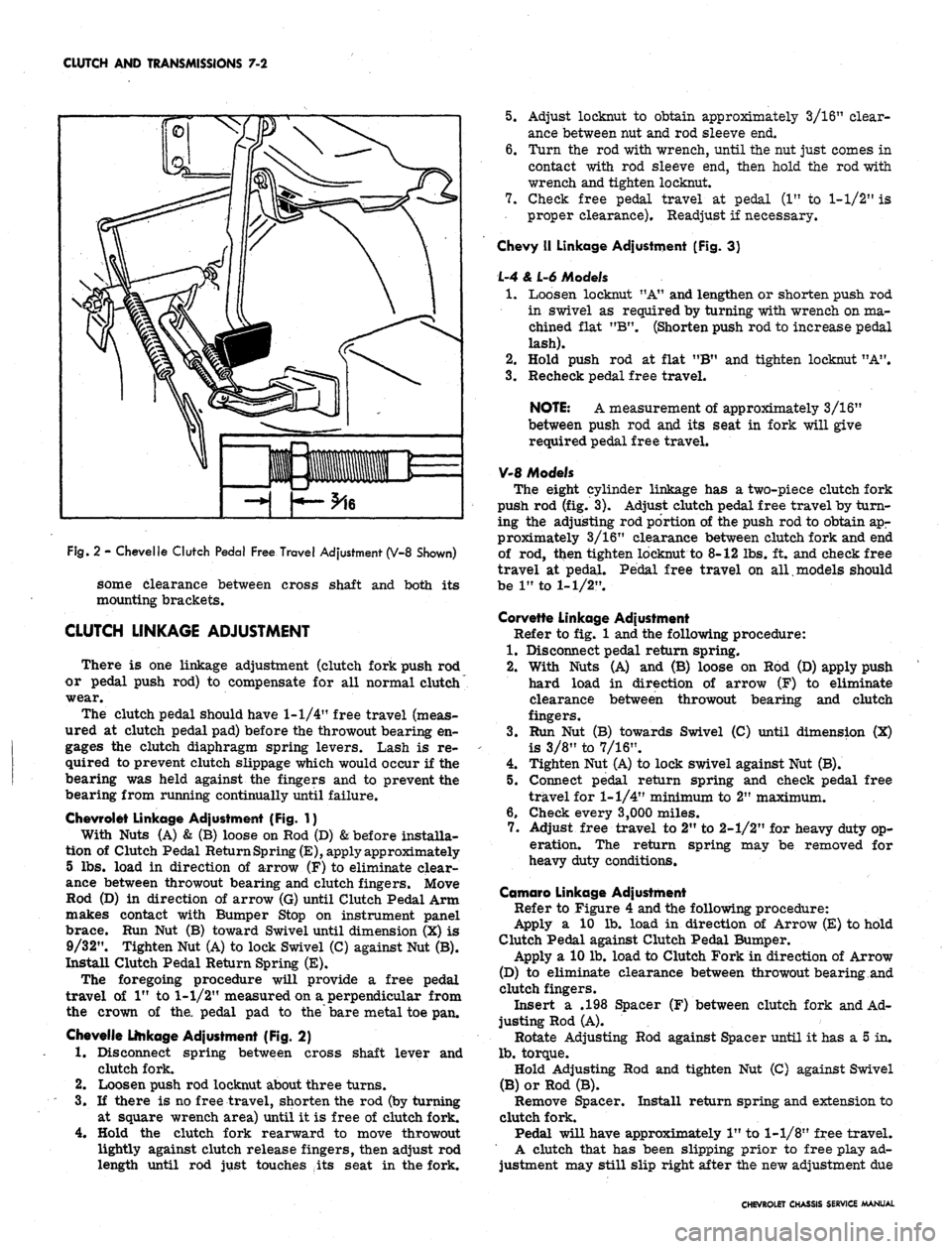
2 - Chevelle Clutch Pedal Free Travel Adjustment (V-8 Shown)
some clearance between cross shaft and both its
mounting brackets.
CLUTCH LINKAGE ADJUSTMENT
There is one linkage adjustment (clutch fork push rod
or pedal push rod) to compensate for all normal clutch
wear.
The clutch pedal should have
1-1/4"
free travel (meas-
ured at clutch pedal pad) before the throwout bearing en-
gages the clutch diaphragm spring levers. Lash is re-
quired to prevent clutch slippage which would occur if the
bearing was held against the fingers and to prevent the
bearing from running continually until failure.
Chevrolet Linkage Adjustment (Fig. 1}
With Nuts (A) & (B) loose on Rod (D)
&
before installa-
tion of Clutch Pedal Return Spring
(E),
apply approximately
5 lbs. load in direction of arrow (F) to eliminate clear-
ance between throwout bearing and clutch fingers. Move
Rod (D) in direction of arrow (G) until Clutch Pedal Arm
makes contact with Bumper Stop on instrument panel
brace. Run Nut (B) toward Swivel until dimension (X) is
9/32". Tighten Nut (A) to lock Swivel (C) against Nut (B).
Install Clutch Pedal Return Spring (E).
The foregoing procedure will provide a free pedal
travel of 1" to
1-1/2"
measured on a perpendicular from
the crown of the, pedal pad to the bare metal toe pan.
Chevelle Linkage Adjustment (Fig. 2)
1.
Disconnect spring between cross shaft lever and
clutch fork.
2.
Loosen push rod locknut about three turns.
3.
If there is no free travel, shorten the rod (by turning
at square wrench area) until it is free of clutch fork.
4.
Hold the clutch fork rearward to move throwout
lightly against clutch release fingers, then adjust rod
length until rod just touches ,its seat in the fork.
5.
Adjust locknut to obtain approximately 3/16" clear-
ance between nut and rod sleeve end.
6. Turn the rod with wrench, until the nut just comes in
contact with rod sleeve end, then hold the rod with
wrench and tighten locknut.
7.
Check free pedal travel at pedal (1" to
1-1/2"
is
proper clearance). Readjust if necessary.
Chevy II Linkage Adjustment (Fig. 3}
L-4 & L-6 Models
1.
Loosen locknut "A" and lengthen or shorten push rod
in swivel as required by turning with wrench on ma-
chined flat "B". (Shorten push rod to increase pedal
lash).
2.
Hold push rod at flat "B" and tighten locknut "A".
3.
Recheck pedal free travel.
NOTE: A measurement of approximately 3/16"
between push rod and its seat in fork will give
required pedal free travel.
V-8 Models
The eight cylinder linkage has a two-piece clutch fork
push rod (fig. 3). Adjust clutch pedal free travel by turn-
ing the adjusting rod portion of the push rod to obtain apr
proximately 3/16" clearance between clutch fork and end
of rod, ttien tighten locknut to 8-12 lbs. ft. and check free
travel at pedal. Pedal free travel on all models should
be 1" to
1-1/2".
Corvette Linkage Adjustment
Refer to fig. 1 and the following procedure:
1.
Disconnect pedal return spring.
2.
With Nuts (A) and (B) loose on Rod (D) apply push
hard load in direction of arrow (F) to eliminate
clearance between throwout bearing and clutch
fingers.
3.
Run Nut (B) towards Swivel (C) until dimension (X)
is 3/8" to 7/16".
4.
Tighten Nut (A) to lock swivel against Nut (B).
5.
Connect pedal return spring and check pedal free
travel for
1-1/4"
minimum to 2" maximum.
6. Check every 3,000 miles.
7.
Adjust free travel to 2" to 2-1/2" for heavy duty op-
eration. The return spring may be removed for
heavy duty conditions.
Camaro Linkage Adjustment
Refer to Figure 4 and the following procedure:
Apply a 10 lb. load in direction of Arrow (E) to hold
Clutch Pedal against Clutch Pedal Bumper.
Apply a 10 lb. load to Clutch Fork in direction of Arrow
(D) to eliminate clearance between throwout bearing and
clutch fingers.
Insert a .198 Spacer (F) between clutch fork and Ad-
justing Rod (A).
Rotate Adjusting Rod against Spacer until it has a 5 in.
lb.
torque.
Hold Adjusting Rod and tighten Nut (C) against Swivel
(B) or Rod (B).
Remove Spacer. Install return spring and extension to
clutch fork.
Pedal will have approximately 1" to
1-1/8"
free travel.
A clutch that has been slipping prior to free play ad-
justment may still slip right after the new adjustment due
CHEVROLET CHASSIS SERVICE MANUAL
Page 363 of 659
CLUTCH AND TRANSMISSIONS 7-4
5.
Install Tool J-5824 to support the clutch assembly
during removal.
NOTE: Look for "X" mark on flywheel and on
clutch cover. If MX" mark is not evident, prick
punch marks on flywheel and clutch cover for
indexing purposes during installation.
6. Loosen the clutch-to-flywheel attaching bolts evenly
1 turn at a time until spring pressure is released,
then remove the bolts, and remove clutch assembly.
Installation to Vehicle
Clean pressure plate and flywheel face. (They should
be free of oil, grease, metal deposits or burned spots).
1.
Position the clutch disc and pressure plate in relar
tive installed position and support them with align-
ment Tool J-5824.
NOTE: The driven disc on the 4 and 6 cylinder
engines is installed with the damfper springs to
the flywheel side; the V-8 is opposite, however,
THE GREASE SLINGER IS ALWAYS ON THE
TRANSMISSION SIDE.
2.
Turn clutch assembly until "X" mark on cover lines
up with "X" mark oh flywheel, then align cover bolt
holes to nearest flywheel holes.
3.
Install a bolt in every hole and tighten down evenly
and gradually until tight (to avoid possible clutch
distortion).
NOTE: Cover loads are as high as 1-1/4 tons.
4.
Remove pilot tool.
5.
Unhook clutch fork and lubricate ball socket and fork
fingers at release bearing end with a high melting
point grease such as graphite and reinstall fork on
ball stud. On Corvette models use Moly Grease.
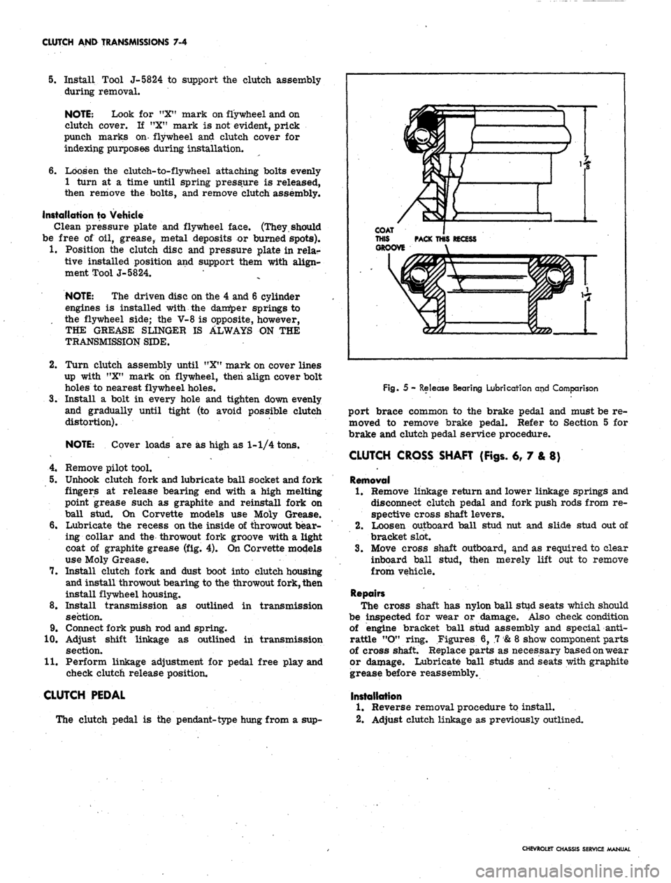
6. Lubricate the recess on the inside of throwout bear-
ing collar and the throwout fork groove with a light
coat of graphite grease (fig. 4). On Corvette models
use Moly Grease.
7.
Install clutch fork and dust boot into clutch housing
and install throwout bearing to the throwout fork, then
install flywheel housing.
8. Install transmission as outlined in transmission
section.
9. Connect fork push rod and spring.
10.
Adjust shift linkage as outlined in transmission
section.
11.
Perform linkage adjustment for pedal free play and
check clutch release position.
CLUTCH PEDAL
The clutch pedal is the pendant-type hung from a sup-
Fig. 5 - Release Bearing Lubrication and Comparison
port brace common to the brake pedal and must be re-
moved to remove brake pedal. Refer to Section 5 for
brake and clutch pedal service procedure.
CLUTCH CROSS SHAFT (Figs. 6, 7 & 8)
Removal
1.
Remove linkage return and lower linkage springs and
disconnect clutch pedal and fork push rods from re-
spective cross shaft levers.
2.
Loosen outboard ball stud nut and slide stud out of
bracket slot.
3.
Move cross shaft outboard, and as required to clear
inboard ball stud, then merely lift out to remove
from vehicle.
Repairs
The cross shaft has nylon ball stud seats which should
be inspected for wear or damage. Also check condition
of engine bracket ball stud assembly and special anti-
rattle "O" ring. Figures 6, .7
&
8 show component parts
of cross shaft. Replace parts as necessary based on wear
or damage. Lubricate ball studs and seats with graphite
grease before reassembly.
Installation
1.
Reverse removal procedure to install.
2.
Adjust clutch linkage as previously outlined.
CHEVROLET CHASSIS SERVICE MANUAL
Page 370 of 659
CLUTCH AND TRANSMISSIONS 7-11
UPPER ARMATURE STOP
(BEND TO ADJUST POINT OPENING)
Fig.
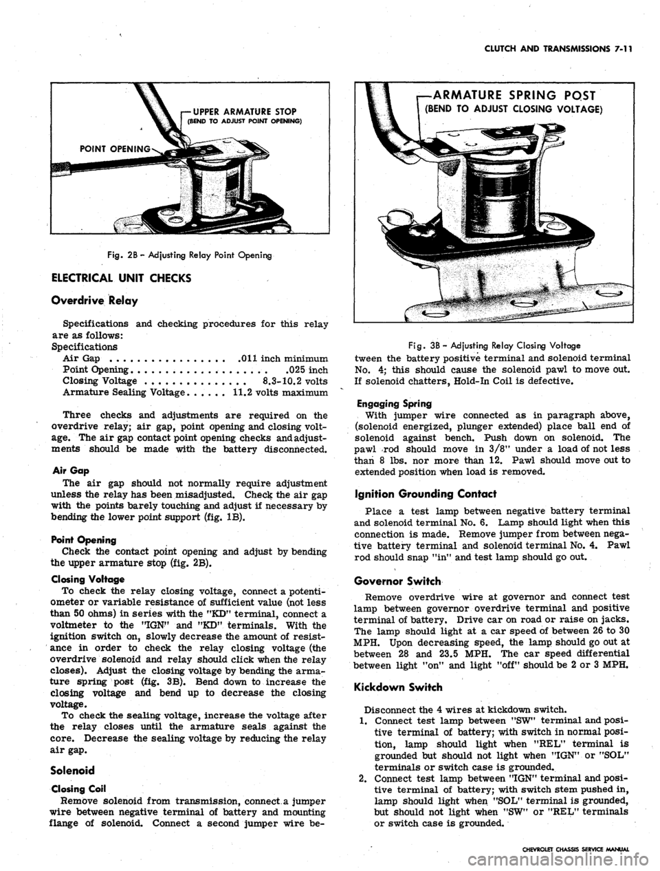
2B-Adjusting Relay Point Opening
ELECTRICAL UNIT CHECKS
Overdrive Relay
Specifications and checking procedures for this relay
are as follows:
Specifications
Air Gap Oil inch minimum
Point Opening .025 inch
Closing Voltage
8.3-10.2
volts
Armature Sealing Voltage. ..... 11.2 volts maximum
Three checks and adjustments are required on the
overdrive relay; air gap, point opening and closing volt-
age.
The air gap contact point opening checks and adjust-
ments should be made with the battery disconnected.
Air Gap
The air gap should not normally require adjustment
unless the relay has been misadjusted. Check the air gap
with the points barely touching and adjust if necessary by
bending the lower point support (fig, IB).
Point Opening
Check the contact point opening and adjust by bending
the upper armature stop (fig. 2B).
Closing Voltage
To check the relay closing voltage, connect a potenti-
ometer or variable resistance of sufficient value (not less
than 50 ohms) in series with the "KD" terminal, connect a
voltmeter to the "IGN" and "KD" terminals. With the
ignition switch on, slowly decrease the amount of resist-
ance in order to check the relay closing voltage (the
overdrive solenoid and relay should click when the relay
closes). Adjust the closing voltage by bending the arma-
ture spring post (fig. 3B). Bend down to increase the
closing voltage and bend up to decrease the closing
voltage.
To check the sealing voltage, increase the voltage after
the relay closes until the armature seals against the
core.
Decrease the sealing voltage by reducing the relay
air gap.
Solenoid
Closing Coil
Remove solenoid from transmission, connect a jumper
wire between negative terminal of battery and mounting
flange of solenoid. Connect a second jumper wire be-
ARMATURE SPRING PQST
(BEND TO ADJUST CLOSING VOLTAGE)
Fig.
3B - Adjusting Relay Closing Voltage
tween the battery positive terminal and solenoid terminal
No.
4; this should cause the solenoid pawl to move out.
If solenoid chatters, Hold-In Coil is defective.
Engaging Spring
With jumper wire connected as in paragraph above,
(solenoid energized, plunger extended) place ball end of
solenoid against bench. Push down on solenoid. The
pawl rod should move in 3/8M under a load of not less
than 8 lbs. nor more than 12. Pawl should move out to
extended position when load is removed.
Ignition Grounding Contact
Place a test lamp between negative battery terminal
and solenoid terminal No. 6. Lamp should light when this
connection is made. Remove jumper from between nega-
tive battery terminal and solenoid terminal No. 4. Pawl
rod should snap "in" and test lamp should go out.
Governor Switch
Remove overdrive wire at governor and connect test
lamp between governor overdrive terminal and positive
terminal of battery. Drive car on road or raise on jacks.
The lamp should light at a car speed of between 26 to 30
MPH. Upon decreasing speed, the lamp should go out at
between 28 and 23.5 MPH. The car speed differential
between light "on" and light "off" should be 2 or 3 MPH.
Kickdown Switch
Disconnect the 4 wires at kickdown switch.
1.
Connect test lamp between "SW" terminal and posi-
tive terminal of battery; with switch in normal posi-
tion, lamp should light when "REL" terminal is
grounded but should not light when "IGN" or "SOL"
terminals or switch case is grounded.
2.
Connect test lamp between "IGN" terminal and posi-
tive terminal of battery; with switch stem pushed in,
lamp should light when "SOL" terminal is grounded,
but should not light when "SW" or "REL" terminals
or switch case is grounded.
CHEVROLET CHASSIS SERVICE MANUAL
Page 371 of 659

CLUTCH AND TRANSMISSIONS 7-12
DIAGNOSIS-OVERDRIVE
MECHANICAL
Any one of the following general complaints may be due
to non-standard mechanical conditions in the overdrive
unit:
1.
Does not drive unless locked up manually.
2.
Does not engage, or lock-up does not release.
3.
Engages with a severe jolt, or noise.
4.
Free-wheels at speeds over 30 mph.
These^ troubles may be diagnosed and remedied as de-
scribed in the following paragraphs.
1.
Does not drive unless locked up manually.
a. Occasionally, the unit may not drive the car for-
ward in direct drive, unless locked up by pulling
the dash control. This may be caused by one or
more broken rollers in the roller clutch, the
remedy for which is the replacement of the entire
set of rollers.
b.
This may also be caused by sticking of the roller
retainer upon the cam. This retainer must move
freely to push the rollers into engaging position,
under the pressure of the two actuating springs.
c. Sometimes this is due to slight indentations, worn
in the cam faces by the rollers spinning, remedied
by replacement of the cam.
2.
Does not engage, or lock-up does not release
.. a. Dash control improperly connected—-Unless the
overdrive dash control wire is connected to the
lockup lever on the left side of the overdrive
housing in such a manner as to move the lever
all the way back when the dash control knob is
pushed in, it may hold the shift rail in such a po-
sition as to interlock the pawl against full engage-
ment resulting in a buzzing noise when overdrive
engagement is attempted.
To correctly make this connection, loosen bind-
ing post at lever, pull dash control knob out 1/4",
move lever all the way to the rear, and tighten
binding post.
b.
Transmission and overdrive improperly aligned—
The same symptoms as above may also result
from misalignment, at assembly, of the overdrive
housing to the transmission case, resulting in
binding of the overdrive shift rail, so that the re-
tractor spring cannot move the rail fully forward,
when the dash control knob is pushed in, and the
transmission is not in reverse. Under such con-
ditions, the unit may remain fully locked up.
To test for this, be sure that the transmission
is not in reverse; disconnect the dash control
wire from the lockup lever, and feel the lever for
free forward movement. If the lever can be
moved forward more than 1/4", it indicates that
misalignment probably exists. To correct this,
Jposen the capscrews between the overdrive hous-
ing and transmission case, and tap the adpater
plate and overdrive housing until a position is
found where the rail shifts freely; tighten cap-
screws.
c. Kickdown switch improperly adjusted—The posi-
tion of the kickdown switch should be adjusted,
by means of the two large nuts which clamp the
switch shank, so the switch plunger travels 3/16"
before the throttle lever touches its stop.
Occasionally the large nuts which clamp the
switch through the switch bracket are tightened
sufficiently to bend the switch shank, thus pre-
venting free motion of the switch stem. This may
usually be remedied by loosening the upper of the
two nuts.
d. Improper installation of solenoid—If car cannot
be rolled backward under any circumstances and
there is no relay click when the ignition is turned
on, it probably indicates that the solenoid has
been installed directly, without twisting into the
bayonet lock between solenoid stem and pawl, thus
jamming the pawl permanently into overdrive en-
gagement. If the car will occasionally roll back-
wards, but not always, (and there is no relay click
when the ignition switch is turned on) it may indi-
cate that, upon installation, the bayonet lock was
caught, and the solenoid forcibly twisted into
alignment with the attaching flange, thus shearing
off the internal keying of the solenoid. Under
these circumstances, the end of the solenoid stem
may not catch in the pawl, and upon release of the
solenoid, the pawl will not be withdrawn promptly
from engagement, but simply drift out. If the
solenoid stem end has its two flats exactly facing
the two solenoid flange holes, it will not withdraw
the pawl properly. If the stem can be rotated
when grasped by a pair of pliers, it indicates that
the internal keying has been sheared.
e. Improper positioning of blocker ring—Occasion-
ally, either in assembly at the factory, or in
service operations in the field, the internal parts
of the overdrive unit may have been rotated with
the solenoid pawl removed, causing the blocker
ring to rotate, so that its two lugs are not located
with respect to- the pawl as shown in Figure 12B.
In other words, the solid portion of the blocker
ring may be in alignment with the pawl, which will
prevent fill} engagement of the pawl with the sun
gear control plate/
To test for this condition, remove solenoid
cover, pull dash control knob out, roll car 2 ft.
forward. Push dash control in, turn ignition
switch on. Then ground the "KD" terminal of
relay, and watch movement of center stem of
solenoid. It should not move more than 1/8" when
the solenoid clicks. Then, with the relay terminal
still grounded, shift into low gear, and roll car
forward by hand. Solenoid stem should then move
an additional 3/8", as the pawl engages fully.
These two tests indicate proper blocker action.
Unless both tests are met, the blocker ring is
probably not in the correct position.
3.
Engages with a severe jolt or noise
Insufficient blocker ring friction may cause the ring
to lose its grip on the hub of the sun gear control
plate. Check the fit and tension of the ring as de-
scribed under "Cleaning and Inspection".
4.
Free-wheels at speeds over 30 MPH
If cam roller retainer spring tension is weak the unit
will free wheel at all times. Check spring action as
described under "Cleaning and Inspection".
CHEVROLET CHASSIS SERVICE MANUAL