carb CHEVROLET CAMARO 1982 Repair Guide
[x] Cancel search | Manufacturer: CHEVROLET, Model Year: 1982, Model line: CAMARO, Model: CHEVROLET CAMARO 1982Pages: 875, PDF Size: 88.64 MB
Page 496 of 875

GM – CAMARO 1982-1992 – Repair Guide (Checked by WxMax) 496
ENGINE BLOCK
ENGINE BLOCK BEARING ALIGNMENT
Remove the main bearing caps and, if sti
ll installed, the main bearing inserts.
Inspect all of the main bearing saddles and caps for damage, burrs or high
spots. If damage is found, and it is caused from a spun main bearing, the block
will need to be align-bored or, if severe enough, replacement. Any burrs or high
spots should be carefully removed with a metal file.
Place a straightedge on the bearing saddles, in the engine block, along the
centerline of the crankshaft. If any cl earance exists between the straightedge
and the saddles, the block must be align-bored.
Align-boring consists of machining th e main bearing saddles and caps by
means of a flycutter that runs through the bearing saddles.
DECK FLATNESS
The top of the engine blo ck where the cylinder head m ounts is called the deck.
Insure that the deck surface is clean of dirt, carbon deposits and old gasket
material. Place a straightedge across the surface of the deck along its
centerline and, using feeler gauges, check the clearance along several points.
Repeat the checking procedure with th e straightedge placed along both
diagonals of the deck surface. If the reading exceeds 0.003 in. (0.076mm)
within a 6.0 in. (15.2cm) span, or 0.006 in . (0.152mm) over the total length of
the deck, it must be machined.
CYLINDER BORES
The cylinder bores house the pistons and are slightly larger than the pistons
themselves. A common piston-to-bor e clearance is 0.0015-0.0025 in.
(0.0381mm-0.0635mm). Inspect and measur e the cylinder bores. The bore
should be checked for out-of-roundness, t aper and size. The results of this
inspection will determine w hether the cylinder can be us ed in its existing size
and condition, or a rebore to the next oversize is required (or in the case of
removable sleeves, have replacements installed).
Page 539 of 875
GM – CAMARO 1982-1992 – Repair Guide (Checked by WxMax) 539
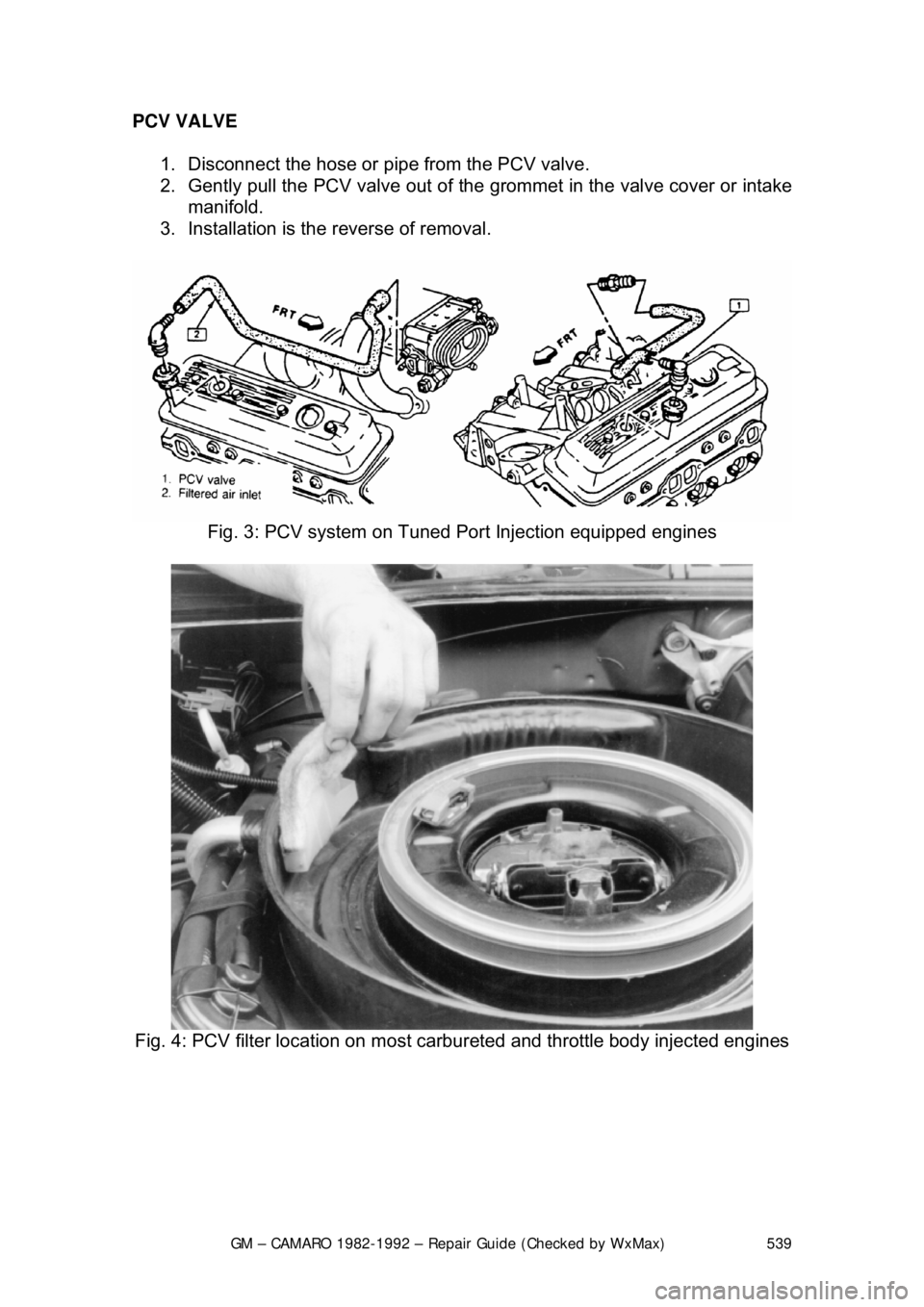
PCV VALVE
1. Disconnect the hose or pi pe from the PCV valve.
2. Gently pull the PCV valv e out of the grommet in the valve cover or intake
manifold.
3. Installation is the reverse of removal.
Fig. 3: PCV system on Tuned Port Injection equipped engines
Fig. 4: PCV filter location on most carbureted and throttle body injected engines
Page 541 of 875
GM – CAMARO 1982-1992 – Repair Guide (Checked by WxMax) 541
EVAPORATIVE EMISS
ION CONTROLS
OPERATION
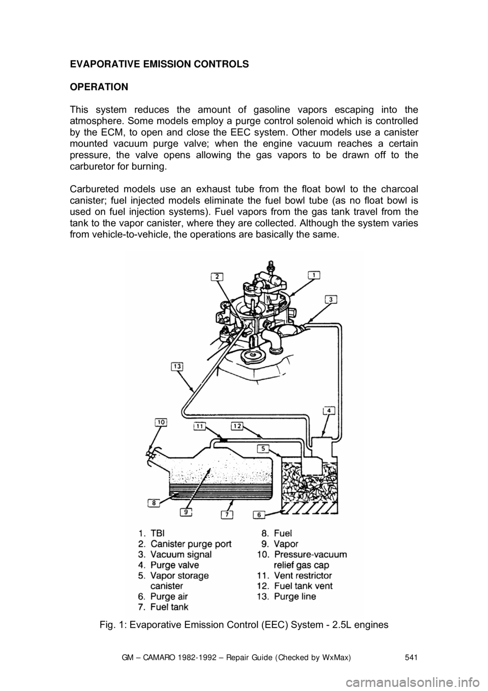
This system reduces the amount of gasoline vapors escaping into the
atmosphere. Some models em ploy a purge control solenoid which is controlled
by the ECM, to open and close the EE C system. Other models use a canister
mounted vacuum purge valve; when the engine vacuum reaches a certain
pressure, the valve opens allowing the gas vapors to be drawn off to the
carburetor for burning.
Carbureted models use an exhaust tube fr om the float bowl to the charcoal
canister; fuel injected models eliminate the fuel bowl tube (as no float bowl is
used on fuel injection systems). Fuel vapor s from the gas tank travel from the
tank to the vapor canister , where they are collected. Although the system varies
from vehicle-to-vehicle, the operat ions are basically the same.
Fig. 1: Evaporative Emission Cont rol (EEC) System - 2.5L engines
Page 542 of 875
GM – CAMARO 1982-1992 – Repair Guide (Checked by WxMax) 542
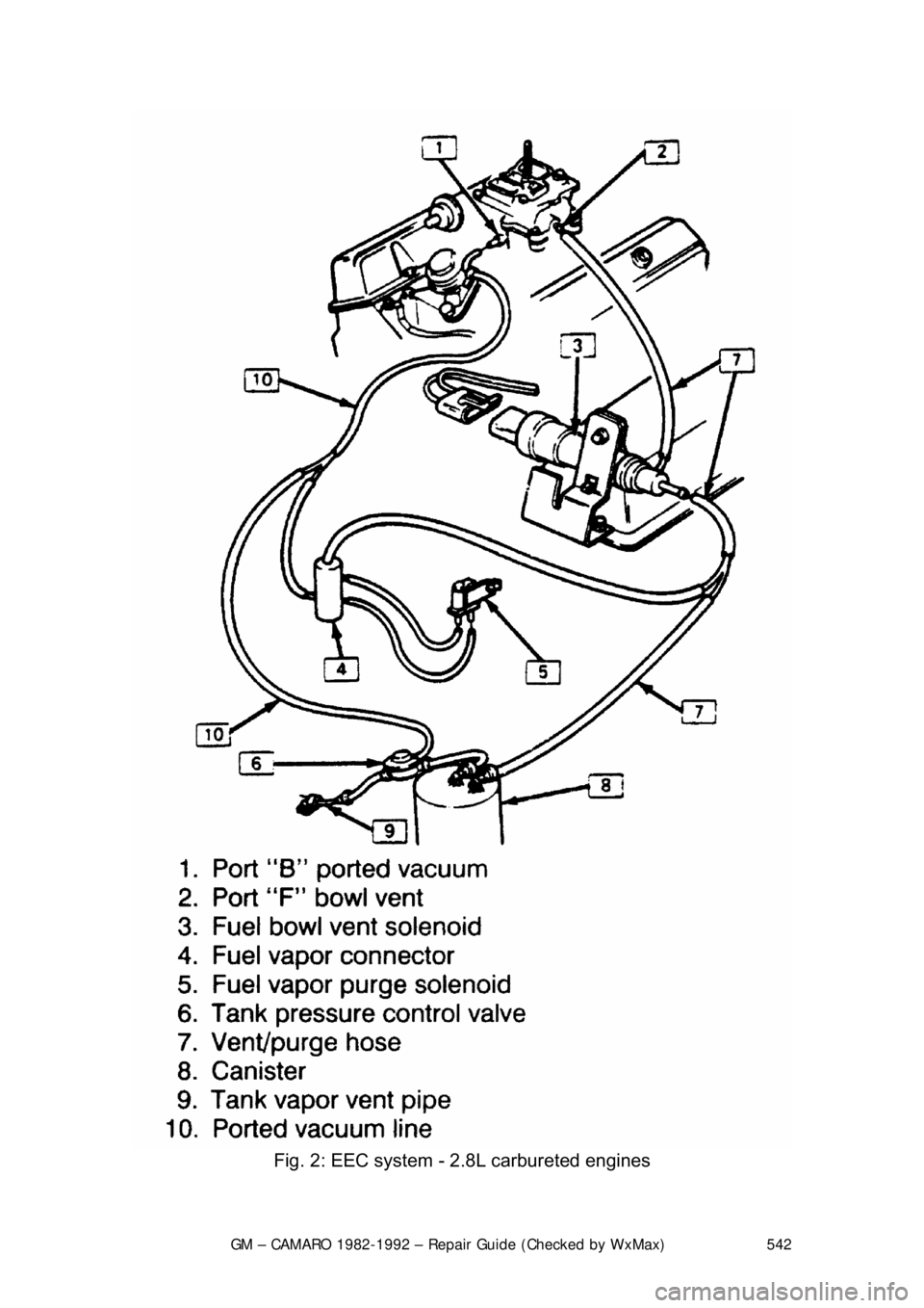
Fig. 2: EEC system - 2.8L carbureted engines
Page 543 of 875
GM – CAMARO 1982-1992 – Repair Guide (Checked by WxMax) 543
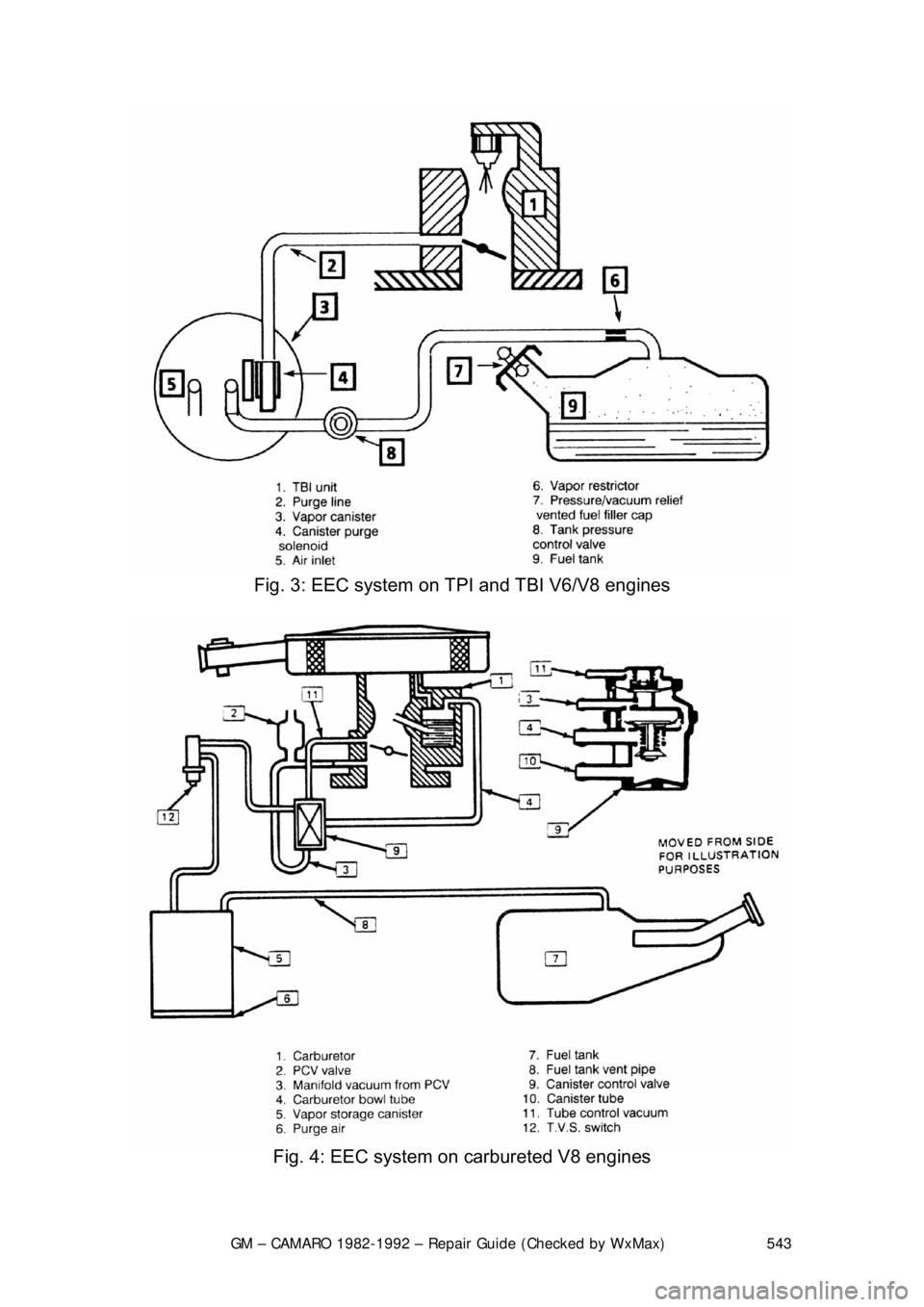
Fig. 3: EEC system on TPI and TBI V6/V8 engines
Fig. 4: EEC system on carbureted V8 engines
Page 547 of 875

GM – CAMARO 1982-1992 – Repair Guide (Checked by WxMax) 547
EXHAUST GAS RECIRCULATION (EGR) SYSTEM
OPERATION
All models are equipped with
this system, which consists of a metering valve, a
vacuum line to the carburet or or intake manifold, and cast-in exhaust passages
in the intake manifold. The EGR valve is controlled by vacuum, which opens
and closes in response to the vacuum signals to admit exhaust gases into the
air/fuel mixture. The exhaust gases lower peak combustion temperatures,
reducing the formation of NOx. The valve is closed at idle and wide open
throttle, but is open between the two extreme positions.
There are actually four types of EGR systems: Ported, Positive Back-Pressure,
Negative Backpressure and Digital. The pr inciple of all the systems are the
same; the only difference is in the me thod used to control how the EGR valve
opens.
Too much EGR flow at idle, cruise or during cold operation may result in the
engine stalling after cold start, the engine stalling at idle after deceleration,
vehicle surge during cruise and rough idle . If the EGR valve is always open, the
vehicle may not idle. Too little or no EGR flow allows combustion temperatures
to rise, which could result in spar k knock (detonation), engine overheating
and/or emission test failure.
A Thermal Vacuum Switch (TVS) or vacuum control solenoid may sometimes\
be used in combination with the EGR va lve. The TVS will close off vacuum
during cold operation. A va cuum control solenoid uses Pulse Width Modulation
(PWM) to turn the solenoid ON and OFF numerous times a second and varies
the amount of ON time (pulse width) to vary the amount of ported vacuum
supplied the EGR valve.
PORTED VALVE
In the ported system, the amount of ex haust gas admitted into the intake
manifold depends on a ported vacuum signal. A ported vacuum signal is one
taken from the carburetor above the th rottle plates; thus, the vacuum signal
(amount of vacuum) is dependent on how far the throttle plates are opened.
When the throttle is closed (idle or dec eleration) there is no vacuum signal.
Thus, the EGR valve is closed, and no exhaust gas enters the intake mani\
fold.
As the throttle is opened, a vacuum is produced, which opens the EGR valve,
admitting exhaust gas into the intake manifold.
POSITIVE BACKPRE SSURE VALVE
This valve operates the same as the ported, except, it has an internal air bleed
that acts as a vacuum regulator. T he bleed valve controls the amount of
vacuum inside the vacuum chamber duri ng operation. When the valve receives
sufficient exhaust backpressure through the hollow shaft, it closes the bleed; at
this point the EGR valve opens.
Page 555 of 875
GM – CAMARO 1982-1992 – Repair Guide (Checked by WxMax) 555
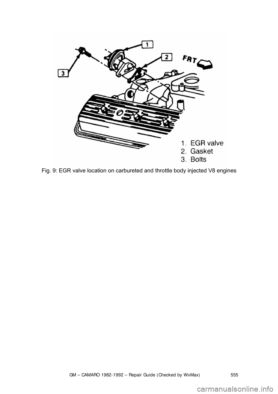
Fig. 9: EGR valve location on carburet ed and throttle body injected V8 engines
Page 559 of 875
GM – CAMARO 1982-1992 – Repair Guide (Checked by WxMax) 559
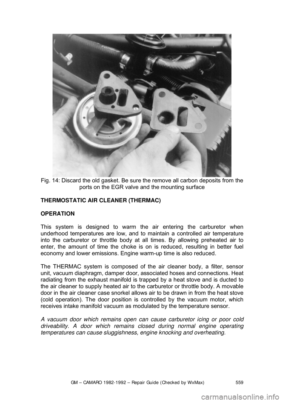
Fig. 14: Discard the old gasket. Be sure the remove all carbon deposits from the
ports on the EGR valve and the mounting surface
THERMOSTATIC AIR CLEANER (THERMAC)
OPERATION
This system is designed to warm the air entering the carburetor when
underhood temperatures are low, and to ma intain a controlled air temperature
into the carburetor or throttle body at all times. By allowing preheated air to
enter, the amount of time t he choke is on is reduced, resulting in better fuel
economy and lower emissions. Engine warm-up time is also reduced.
The THERMAC system is composed of th e air cleaner body, a filter, sensor
unit, vacuum diaphragm, damper door, a ssociated hoses and connections. Heat
radiating from the exhaust manifold is tr apped by a heat stove and is ducted to
the air cleaner to supply heated air to t he carburetor or throttle body. A movable
door in the air cleaner case snorkel allows air to be drawn in from the heat stove
(cold operation). The door position is co ntrolled by the vacuum motor, which
receives intake manifold vacuum as modulated by the temperature sensor.
A vacuum door which remain s open can cause carburetor icing or poor cold
driveability. A door which remains clos ed during normal engine operating
temperatures can cause sluggishne ss, engine knocking and overheating.
Page 569 of 875
GM – CAMARO 1982-1992 – Repair Guide (Checked by WxMax) 569
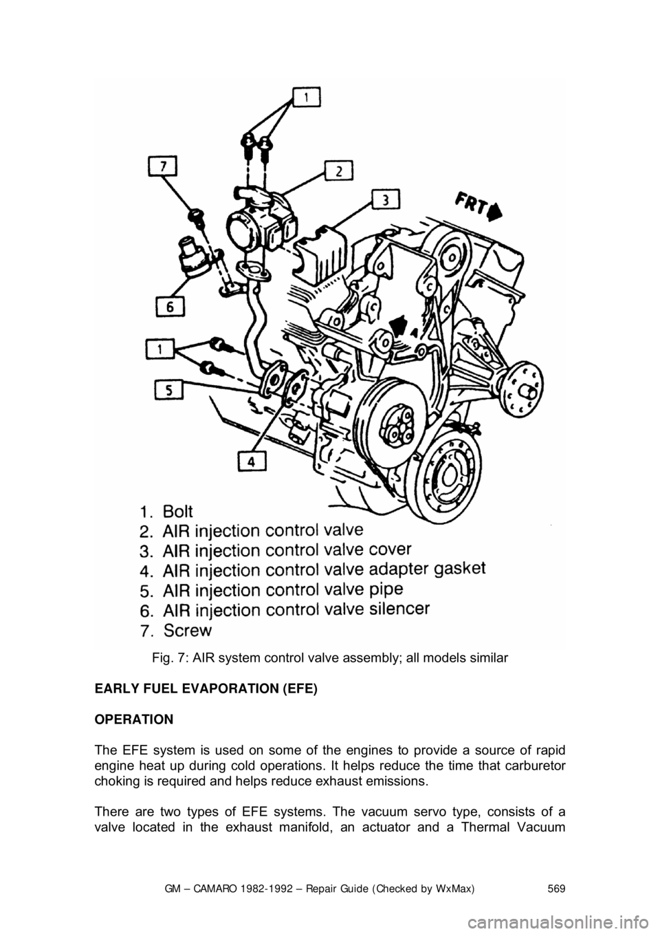
Fig. 7: AIR system control valv e assembly; all models similar
EARLY FUEL EVAPORATION (EFE)
OPERATION
The EFE system is used on some of the engines to provide a source of rapid
engine heat up during cold operations. It hel ps reduce the time that carburetor
choking is required and helps reduce exhaust emissions.
There are two types of EF E systems. The vacuum servo type, consists of a
valve located in the exhaust manifold , an actuator and a Thermal Vacuum
Page 570 of 875

GM – CAMARO 1982-1992 – Repair Guide (Checked by WxMax) 570
Switch (TVS). The electrical type, cons
ists of a ceramic grid located under the
base of the carburetor.
A check of the operation should be made at regular maintenance intervals.
TESTING
VACUUM SERVO TYPE 1. With the engine cold, observe the posit ion of the actuator arm. Start the
engine. The arm should move toward the diaphragm (closing the valve).
2. If the arm does not move, remove the hose and check for vacuum. If still
no vacuum, remove the top hose from the TVS switch and check for
vacuum.
3. If vacuum is present in the top hose, replace the TVS switch.
4. If vacuum is present at the actuator and it does not move, try to free the
valve. If the valve cannot be freed, it must be replaced.
ELECTRICAL TYPE 1. Turn the ignition ON with the engine co ld and probe both terminals of the
heater switch connector with a test light.
• If 1 wire has power, replace the heater switch.
• If neither wire has power, repai r the ignition circuit.
• If both wires have power, probe the pink wire at the heater
connector (if no power, repair the c onnector of the heater switch).
2. If power exists at the pink wire , disconnect the heater connector and
connect a tester across the harness terminal. If no power, repair the
ground wire; if power exists, check the resistance of the heater.
3. If heater is over 3 ohm s, replace the heater. If under 3 ohms, replace the
connector, start the engine (operate to normal temperature) and probe
the pink wire. If no power, the system is OK; if power exists, replace the
heater switch.
REMOVAL & INSTALLATION
VACUUM SERVO TYPE 1. Disconnect the vacuum hose at the EFE.
2. Remove exhaust pipe to manifold nuts.
3. Remove the crossover pipe. Complete removal is not always necessary.
4. Remove the EFE valve.
To install: 5. Position the EFE valve into place.
6. Install the crossover pipe.
7. Install the exhaust pi pe to manifold nuts.
8. Connect the vacuum hose at the EFE.