carb CHEVROLET CAMARO 1982 Repair Guide
[x] Cancel search | Manufacturer: CHEVROLET, Model Year: 1982, Model line: CAMARO, Model: CHEVROLET CAMARO 1982Pages: 875, PDF Size: 88.64 MB
Page 346 of 875

GM – CAMARO 1982-1992 – Repair Guide (Checked by WxMax) 346
battery, electricity is forced into the battery
, and the battery is returned to its fully
charged state.
Alternators are used on the modern autom obiles for they are lighter, more
efficient, can rotate at higher speeds and have fewer brush problems. In an
alternator, the field rotates while al l the current produced passes only through
the stators windings. The brushes bear agains t continuous slip rings rather than
a commutator. This causes the current produced to periodically reverse the
direction of its flow. Diodes (electrica l one-way switches) block the flow of
current from traveling in t he wrong direction. A series of diodes is wired together
to permit the alternating flow of the st ator to be converted to a pulsating, but
unidirectional flow at the alternator out put. The alternator's field is wired in
series with the voltage regulator.
Please refer to Engine Performance & Tune-up for ignition system testing
procedures.
IGNITION COIL
REMOVAL & INSTALLATION
INTERNALLY MOUNTED COIL 1. Disconnect and label the wires from cap.
2. Remove the distributor cap from the distributor.
3. On the distributor cap, remove t he coil cover attaching screws and the
cover.
4. Remove the ignition coil attaching screws and lift the coil from the cap.
To install: 5. Position the coil and secure it with the attaching screws. Be sure to install
the carbon button and rubber disc first.
6. Install the coil cover and attaching screws.
7. Install the distributor cap.
8. Connect the wires to the cap.
EXTERNALLY MOUNTED COIL 1. Label and disconnect the wires from the coil.
2. Remove the ignition coil mounting bolts and the coil.
To install: 3. To install, position the coil into place and se cure it with the mounting
bolts.
4. Connect the wires to the coil.
IGNITION MODULE
Page 382 of 875
GM – CAMARO 1982-1992 – Repair Guide (Checked by WxMax) 382
11. Position the manifold into place and install manifold attaching bolts.
Torque manifold bolts to specificat ion (see illustration for tightening
sequence and torque specifications).
12. Install the air conditioning comp ressor and compressor support brackets,
if so equipped.
13. Connect the coolant inlet and outlet hoses to the intake manifold.
14. Connect the linkage to the TBI unit (throttle, downshift, and/or cruise
control, as applicable).
15. Connect the vacuum lines and the elec trical connections to the TBI unit.
16. Connect the fuel lines to the Th rottle Body Injection (TBI) unit.
17. Install the PCV valve and hose.
18. Install the air cleaner assembly.
19. Connect the negative battery cable at the battery.
20. Fill the cooling system.
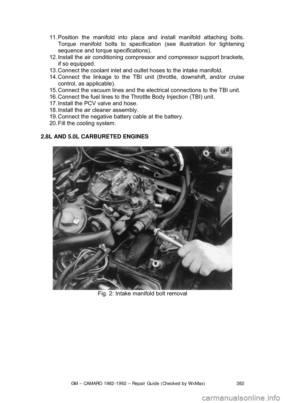
2.8L AND 5.0L CARBURETED ENGINES
Fig. 2: Intake manifold bolt removal
Page 384 of 875
GM – CAMARO 1982-1992 – Repair Guide (Checked by WxMax) 384
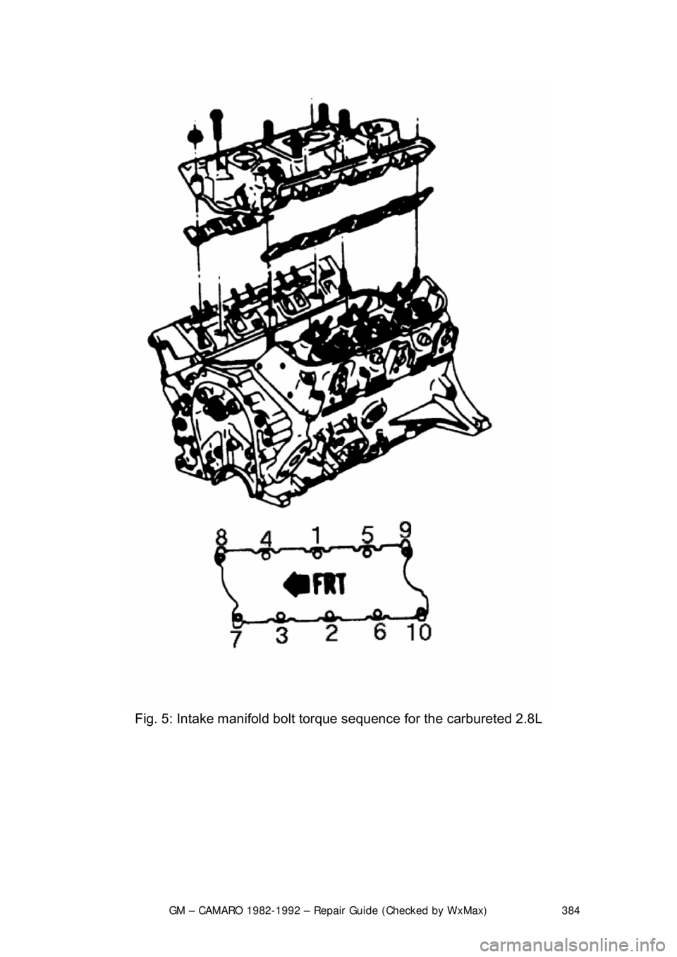
Fig. 5: Intake manifold bolt to rque sequence for the carbureted 2.8L
Page 386 of 875

GM – CAMARO 1982-1992 – Repair Guide (Checked by WxMax) 386
FUEL INJECTION
1. Remove the air cleaner.
2. Drain the radiator.
3. Disconnect: a. Battery cables at the battery.
b. Upper radiator and heater hoses at the manifold.
c. Crankcase ventilation hoses as required.
d. Fuel line at the carburetor.
e. Accelerator linkage.
f. Vacuum hose at the distributor, if equipped.
g. Power brake hose at the car buretor base or manifold, if
applicable.
h. Temperature sending switch wires.
4. Remove the distributor cap and scribe the rotor position relative to the
distributor body, and engine.
5. Remove the distributor.
6. If applicable, remove the alternator upper bracket. As required, remove
the air cleaner bracket, and accelerator bellcrank.
7. Remove the manifold-to-head attachi ng bolts, then remove the manifold
and carburetor as an assembly.
8. Mark and disconnect all emission re lated items (e.g.: wiring, vacuum
hoses, etc.) which are connected to manifold mounted items.
9. If the manifold is to be replaced , transfer the carburetor (and mounting
studs), water outlet and thermostat (use a new gasket) heater hose
adapter, EGR valve (use new gasket) and, if applicable, TVS switch(s)
and the choke coil.
To install: 10. Before installing the manifold, thoroughly clean the gasket and sealing
surfaces of the cylinder heads and manifold.
11. Install the manifold end seals, folding the tabs if applicable, and the
manifold/head gaskets, using a s ealing compound around the water
passages.
Make sure that the new manifold gaskets match the old ones EXACTLY.
12. When installing the manifold, care should be taken not to dislocate the
end seals. It is helpful to use a pilo t in the distributor opening. Tighten the
manifold bolts to 30 ft. lbs. (40 Nm) for 5.0L or 20-25 ft. lbs. (27-34 Nm)
for 2.8L in the sequence illustrated.
13. Install the distributor with the rotor in its original location as indicated by
the scribe line. If the engi ne has been disturbed, refer to the previous
Distributor Removal and Installation procedure.
14. If applicable, install the alter nator upper bracket and adjust the belt
tension.
15. Connect all disconnected components at their original locations.
16. Fill the cooling system, start the engine, check for leaks and adjust the
ignition timing and carburetor idle speed and mixture.
Page 397 of 875
GM – CAMARO 1982-1992 – Repair Guide (Checked by WxMax) 397
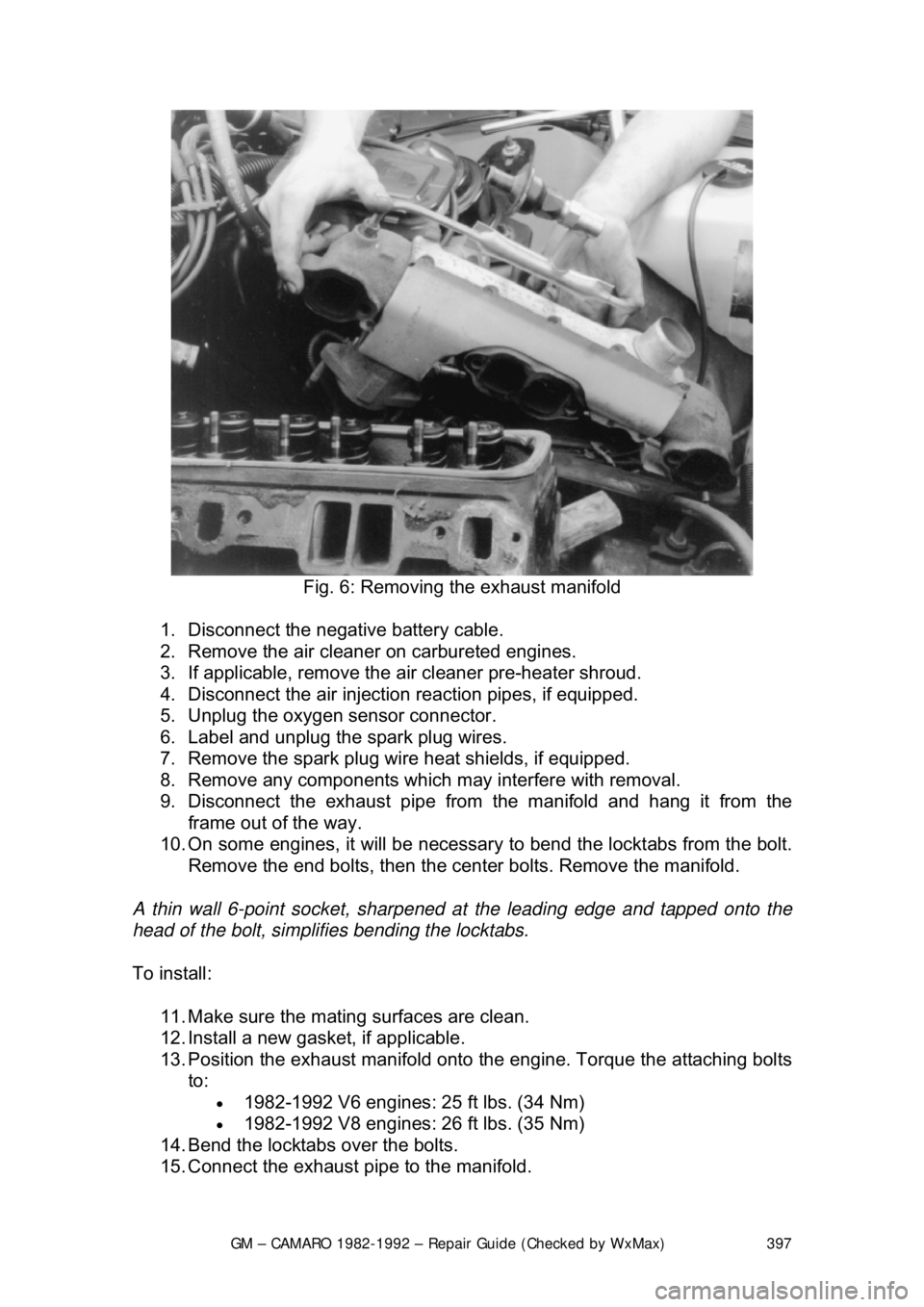
Fig. 6: Removing the exhaust manifold
1. Disconnect the negative battery cable.
2. Remove the air cleaner on carbureted engines.
3. If applicable, remove the ai r cleaner pre-heater shroud.
4. Disconnect the air injecti on reaction pipes, if equipped.
5. Unplug the oxygen sensor connector.
6. Label and unplug the spark plug wires.
7. Remove the spark plug wire heat shields, if equipped.
8. Remove any components which may interfere with removal.
9. Disconnect the exhaust pipe from the manifold and hang it from the
frame out of the way.
10. On some engines, it will be necessary to bend the locktabs from the bolt.
Remove the end bolts, then the center bolts. Remove the manifold.
A thin wall 6-point socket, sharpened at the leading edge and tapped onto the
head of the bolt, simplifies bending the locktabs.
To install:
11. Make sure the mating surfaces are clean.
12. Install a new gasket, if applicable.
13. Position the exhaust manifold onto the engine. Torque the attaching bolts
to:
• 1982-1992 V6 engines: 25 ft lbs. (34 Nm)
• 1982-1992 V8 engines: 26 ft lbs. (35 Nm)
14. Bend the locktabs over the bolts.
15. Connect the exhaust pipe to the manifold.
Page 441 of 875

GM – CAMARO 1982-1992 – Repair Guide (Checked by WxMax) 441
2. Remove the fan, driv
e belts and water pump pul ley. Remove the valve
cover. Loosen the rocker arms and pivot them, then remove the
pushrods.
3. Remove the oil pump driveshaft and gear assembly. This is located
under a small plate secured by two bol ts near the oil filter. Remove the
spark plugs.
4. Mark the position of the distribut or rotor, housing, and engine block.
Remove the distributor.
5. Remove the valve lifters. They are located behind the pushrod cover.
6. Remove the timing gear cover.
7. Insert a screwdriver through the holes in the ti ming gear and remove the
2 camshaft thrust plate screws.
8. Pull the camshaft and gear assembly out through the front of the engine
block.
When removing the camshaft, be careful not to damage the camshaft bearings.
9. If the camshaft is to be removed from the timing gear, place the assembly in an arbor press and s eparate. CAUTION When removing the
timing gear from the camshaft, the thrust plate must be positioned so that
the woodruff key does not damage it.
To install: 10. To install the timing gear to the camshaft, press the assembly together
and measure the end clearance. T here should be 0.0015-0.0050 in.
(0.038-0.127mm) between the thrust plate and the camshaft.
If the clearance is less than 0.0015 in. (0 .038mm), replace the spacer ring; if
more than 0.0050 in. (0.127mm), replace the thrust ring.
11. Lubricate the camshaft, bearings, and lifters. Slide the camshaft
assembly into the engine and align the timing marks of the camshaft gear
and crankshaft gear.
12. Complete the installation by reversing the removal procedure.
V6 AND V8 ENGINES 1. Remove the engine from the vehicl e or remove all components from the
front of the engine (radi ator, grille, etc.).
2. Remove the timing gear cover and chain.
3. Mark the distributor rotor, housi ng and engine block, then remove the
distributor. Remove the fuel pump and fuel pump pushrod on carbureted
engines.
4. Remove the intake manifold and valve covers. Loosen the rocker arms
and pivot out of way. Remove the pushrods and valve lifters.
5. Remove the oil pump drive.
6. Slide the camshaft toward the front of the engine (be careful not to
damage the camshaft bearings).
Page 449 of 875

GM – CAMARO 1982-1992 – Repair Guide (Checked by WxMax) 449
1. Remove the intake manifold, valve
cover and pushrod cover (4-cylinder).
Disassemble the rocker arms and remove the pushrods.
2. Remove the lifters. If they are coat ed with varnish, clean with carburetor
cleaning solvent.
3. If installing new lifters or you have disassembled the lifters, they must be
primed before installation. Submer ge the lifters in SAE 10 oil and
carefully push down on the plunger with a
1/8 in. (3mm) drift. Hold the
plunger down (DO NOT pum p), then release the plunger slowly. The lifter
is now primed.
4. Coat the bottoms of the lifters wit h Molykote® before installation. Install
the lifters and pushrods into the e ngine in their original position.
5. Install the rocker arms and adjust the valves. Complete the installation by
reversing the removal procedure.
FREEZE PLUGS
REMOVAL & INSTALLATION
CAUTION - When draining the coolant, keep in mind that cats and dogs are
attracted by the ethylene gl ycol antifreeze, and are quite likely to drink any that
is left in an uncovered container or in puddles on the ground. This will prove
fatal in sufficient quantity. Always drai n the coolant into a sealable container.
Coolant should be reused unless it is contaminated or several years old.
1. Disconnect the negative battery cable.
2. Drain the cooling system.
3. Raise and support the vehicle safely.
4. Remove the coolant drain plug on t he side of the block, if equipped. If not
you can use a punch to put a small ho le in the center of the freeze plug
that is being replaced.
5. Remove all components in order to gain access to the freeze plug(s).
6. Using a punch, tap the bottom corner of the freeze plug to cock it in the
bore. Remove the plug using pliers.
7. Clean the freeze plug hole and c oat the new plug with sealer.
8. Using a suitable tool, install the freeze plug into the block.
9. Connect the negative battery cable, fill the cooling system, start the
engine and check for leaks.
REAR MAIN OIL SEAL
REMOVAL & INSTALLATION
CAUTION - The EPA warns that prol onged contact with used engine oil may
cause a number of skin disorders, incl uding cancer! You should make every
effort to minimize your exposure to used engine oil. Pr otective gloves should be
worn when changing the oil. Wash y our hands and any other exposed skin
areas as soon as possible after exposure to used engine oil. Soap and water, or
waterless hand cleaner should be used.
1-PIECE NEOPRENE SEAL
Page 470 of 875
GM – CAMARO 1982-1992 – Repair Guide (Checked by WxMax) 470
•
Never hot tank aluminum parts (the c austic hot tank solution will eat the
aluminum.
• Remove all aluminum parts (identif ication tag, etc.) from engine parts
prior to the tanking.
• Always coat threads lightly with engine oil or anti-seize compounds
before installation, to prevent seizure.
• Never overtighten bolts or spark plugs especially in aluminum threads.
When assembling the engine, any parts that will be exposed to frictional contact
must be prelubed to provide lubricatio n at initial start-up. Any product
specifically formulated for this purpos e can be used, but engine oil is not
recommended as a prelube in most cases.
When semi-permanent (locked, but removabl e) installation of bolts or nuts is
desired, threads should be cleaned and coat ed with Loctite® or another similar,
commercial non-hardening sealant.
CLEANING
Before the engine and its components ar e inspected, they must be thoroughly
cleaned. You will need to remove any eng ine varnish, oil sludge and/or carbon
deposits from all of the com ponents to insure an accurate inspection. A crack in
the engine block or cylinder head can eas ily become overlooked if hidden by a
layer of sludge or carbon.
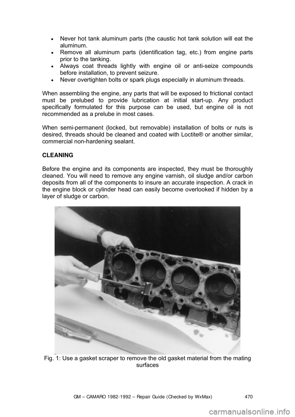
Fig. 1: Use a gasket scraper to remove t he old gasket material from the mating
surfaces
Page 471 of 875
GM – CAMARO 1982-1992 – Repair Guide (Checked by WxMax) 471
Most of the cleaning process can
be carried out with common hand tools and
readily available solvents or soluti ons. Carbon deposits can be chipped away
using a hammer and a hard wooden chisel. Old gasket material and varnish or
sludge can usually be re moved using a scraper and/ or cleaning solvent.
Extremely stubborn deposits may require the use of a power drill with a wire
brush. If using a wire brush, use extrem e care around any critical machined
surfaces (such as the gasket surfaces, bearing saddles, cylinder bores, etc.).
Use of a wire brush is NOT RECO MMENDED on any aluminum components.
Always follow any safety recommendations given by the manufacturer of the
tool and/or solvent. You s hould always wear eye prot ection during any cleaning
process involving scraping, chipping or spraying of solvents.
An alternative to the mess and hassle of cl eaning the parts yourself is to drop
them off at a local garage or machine shop. They will, more than likely, have the
necessary equipment to properly clean all of the parts for a nominal fee.
CAUTION - Always wear eye protection duri ng any cleaning process involving
scraping, chipping or spraying of solvents.
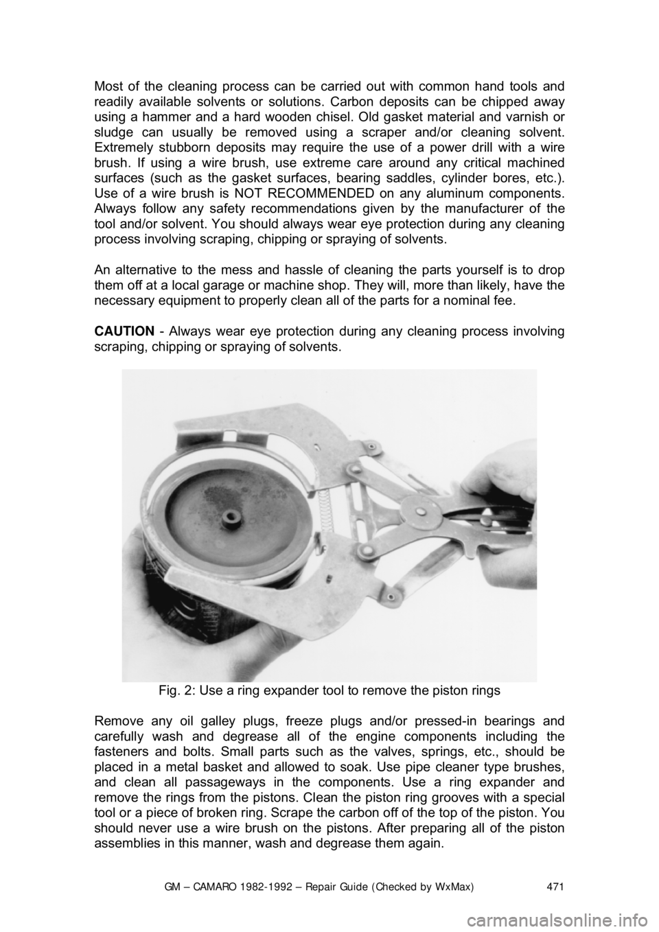
Fig. 2: Use a ring expander tool to remove the piston rings
Remove any oil galley plugs, freeze pl ugs and/or pressed-in bearings and
carefully wash and degrease all of the engine components including the
fasteners and bolts. Small par ts such as the valves, springs, etc., should be
placed in a metal basket and allowed to soak. Use pipe cleaner type brushes,
and clean all passageways in the co mponents. Use a ring expander and
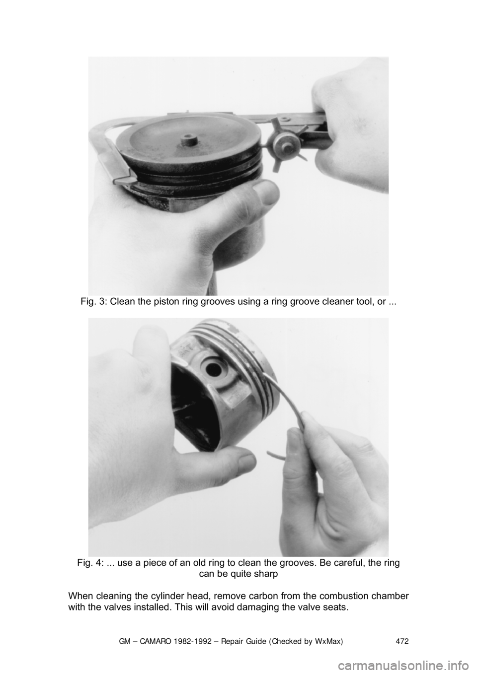
remove the rings from the pistons. Cl ean the piston ring grooves with a special
tool or a piece of broken ri ng. Scrape the carbon off of the top of the piston. You
should never use a wire brush on the pist ons. After preparing all of the piston
assemblies in this manner, wash and degrease them again.
Page 472 of 875
GM – CAMARO 1982-1992 – Repair Guide (Checked by WxMax) 472
Fig. 3: Clean the piston ring grooves using a ring groove cleaner tool, or ...
Fig. 4: ... use a piece of an old ring to clean the grooves. Be careful,\
the ring
can be quite sharp
When cleaning the cylinder head, remove carbon from the combustion chamber
with the valves installed. This will avoid damaging the valve seats.