carb CHEVROLET CAMARO 1982 Repair Guide
[x] Cancel search | Manufacturer: CHEVROLET, Model Year: 1982, Model line: CAMARO, Model: CHEVROLET CAMARO 1982Pages: 875, PDF Size: 88.64 MB
Page 620 of 875
GM – CAMARO 1982-1992 – Repair Guide (Checked by WxMax) 620
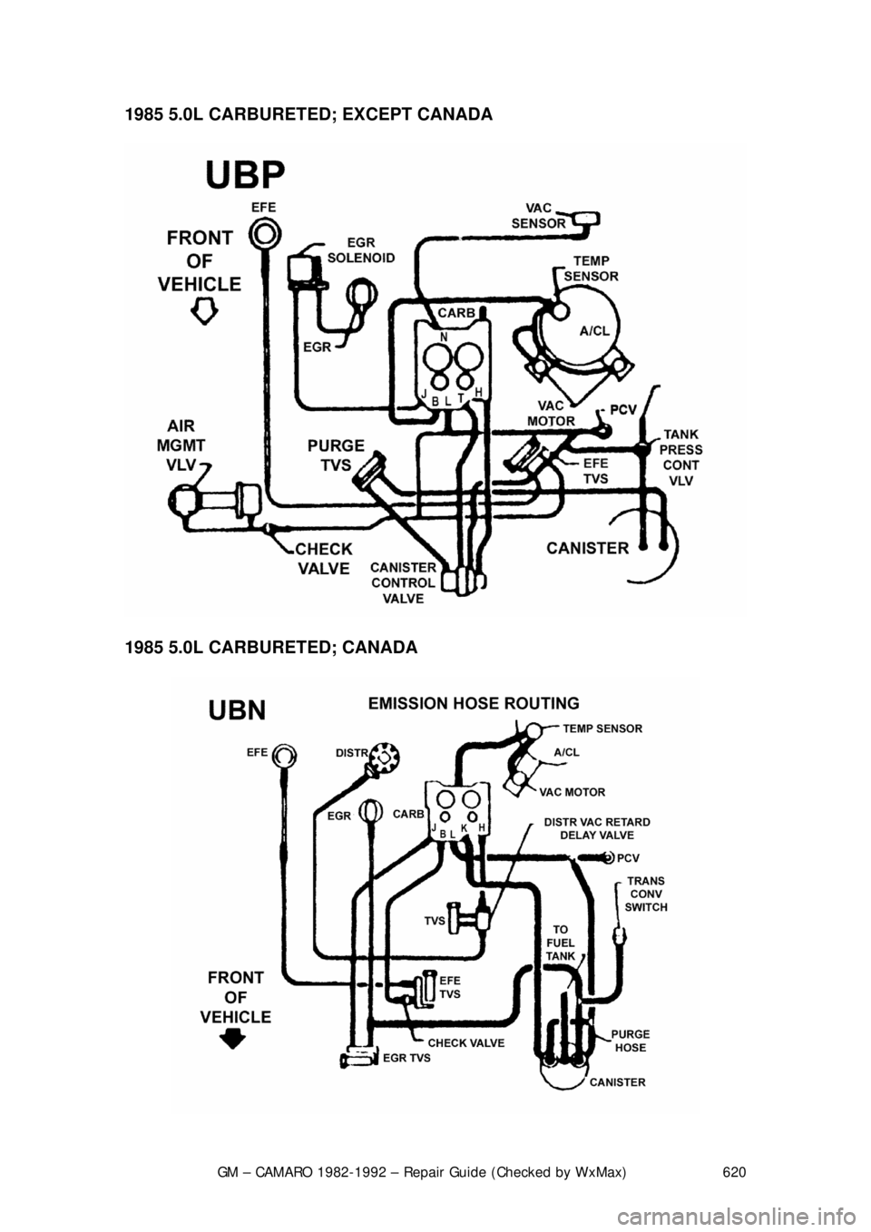
1985 5.0L CARBURETED;
EXCEPT CANADA
1985 5.0L CARBURETED; CANADA
Page 621 of 875
GM – CAMARO 1982-1992 – Repair Guide (Checked by WxMax) 621
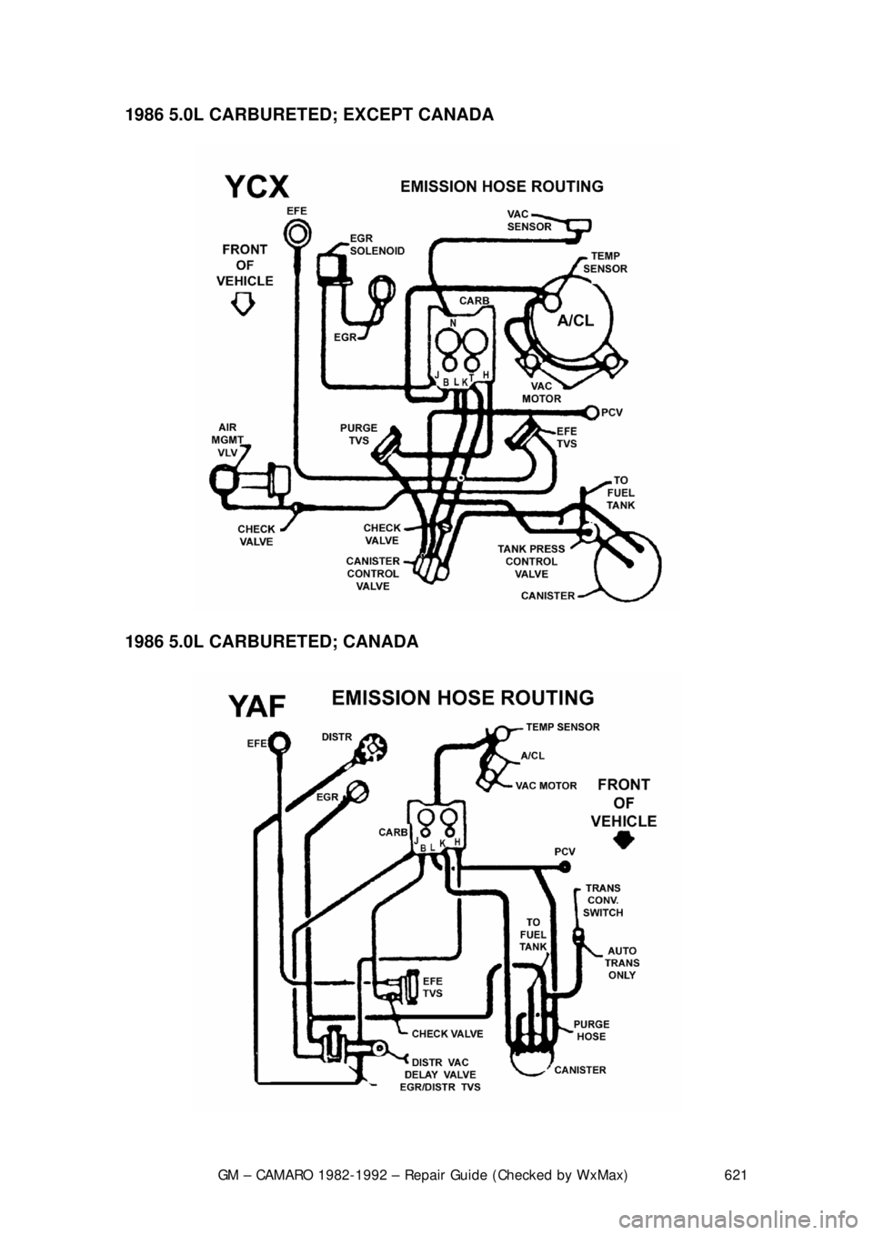
1986 5.0L CARBURETED;
EXCEPT CANADA
1986 5.0L CARBURETED; CANADA
Page 622 of 875
GM – CAMARO 1982-1992 – Repair Guide (Checked by WxMax) 622
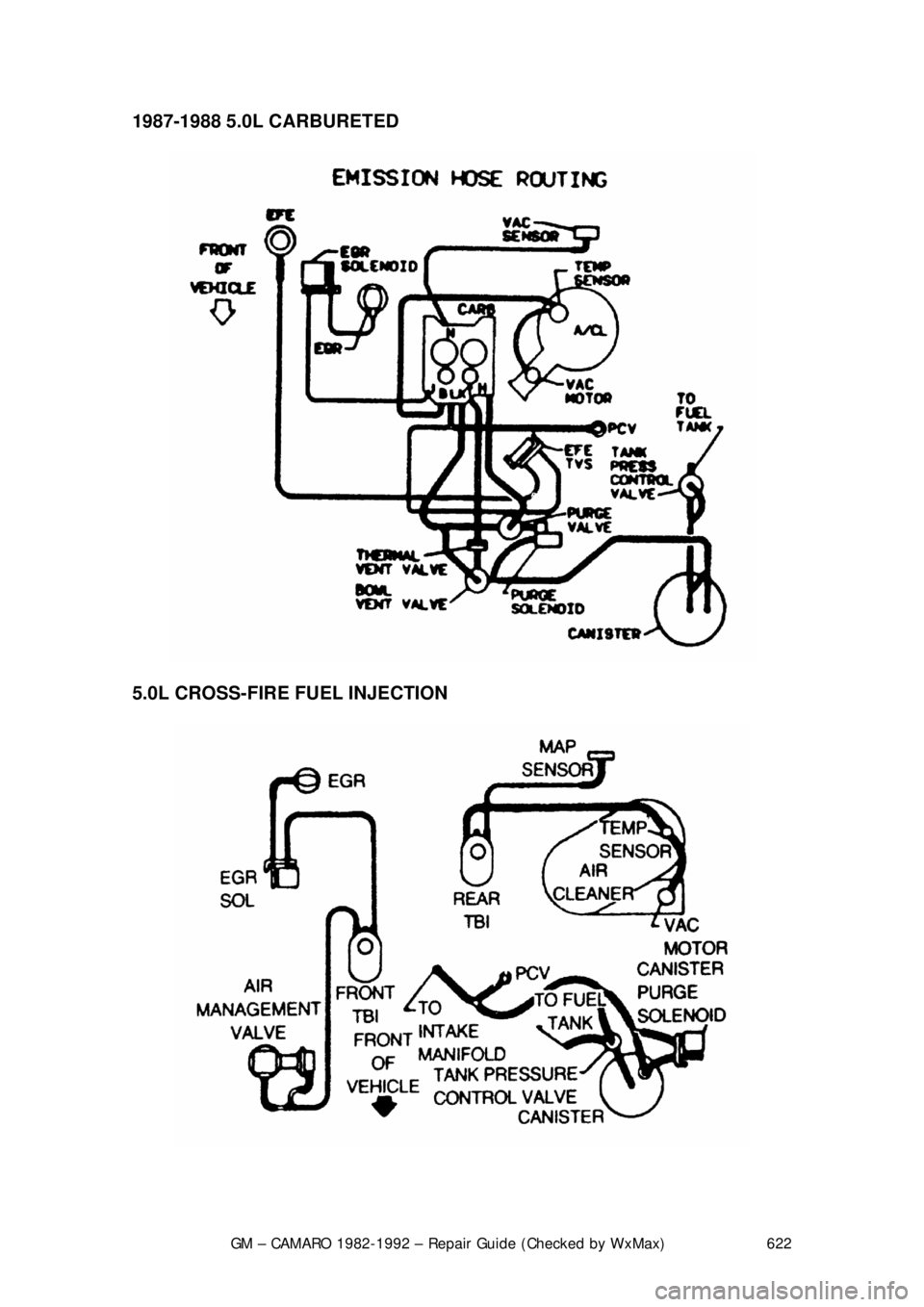
1987-1988 5.0L CARBURETED
5.0L CROSS-FIRE FUEL INJECTION
Page 628 of 875
GM – CAMARO 1982-1992 – Repair Guide (Checked by WxMax) 628
SPARK PLUG HEAT RANGE
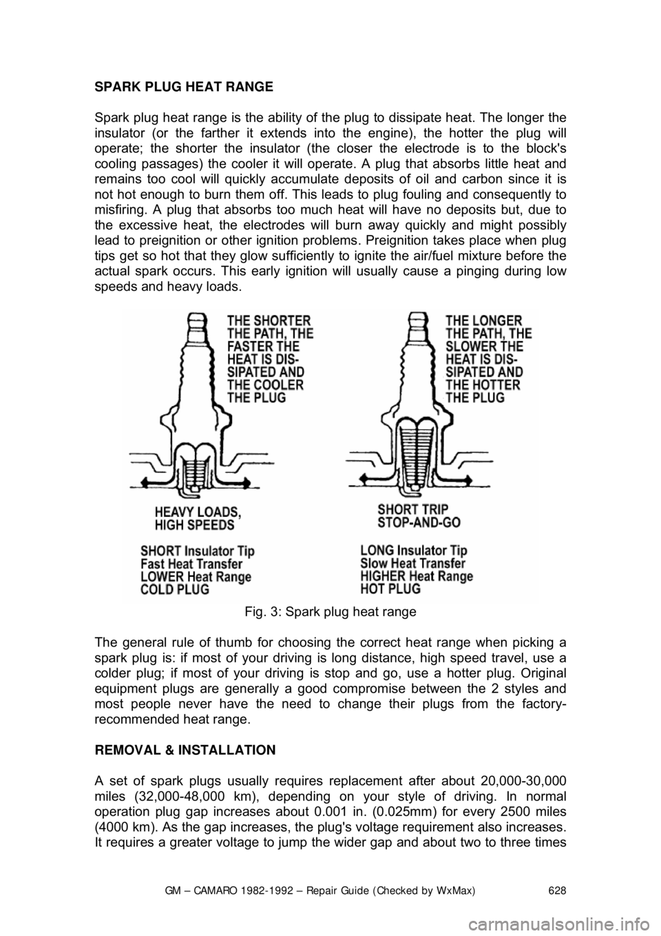
Spark plug heat range is
the ability of the plug to dissipate heat. The longer the
insulator (or the farther it extends in to the engine), the hotter the plug will
operate; the shorter the insulator (the cl oser the electrode is to the block's
cooling passages) the cooler it will operate. A plug that absorbs little heat and
remains too cool will quickly accumulate deposits of oil and carbon since it is
not hot enough to burn them off. This leads to plug fouling and consequently to
misfiring. A plug that absorbs too much heat will have no deposits but, due to
the excessive heat, the electrodes will burn away quickly and might possibly
lead to preignition or other ignition probl ems. Preignition takes place when plug
tips get so hot that they gl ow sufficiently to ignite the air/fuel mixture before the
actual spark occurs. This early igniti on will usually cause a pinging during low
speeds and heavy loads.
Fig. 3: Spark plug heat range
The general rule of thumb for choosing the correct heat range when picking a
spark plug is: if most of your driving is long distanc e, high speed travel, use a
colder plug; if most of your driving is stop and go, use a hotter plug. Original
equipment plugs are general ly a good compromise between the 2 styles and
most people never have the need to change their plugs from the factory-
recommended heat range.
REMOVAL & INSTALLATION
A set of spark plugs usually requi res replacement after about 20,000-30,000
miles (32,000-48,000 km), depending on y our style of driving. In normal
operation plug gap increases about 0.001 in. (0.025mm) for every 2500 miles
(4000 km). As the gap increases, the plug' s voltage requirement also increases.
It requires a greater voltage to jump t he wider gap and about two to three times
Page 641 of 875

GM – CAMARO 1982-1992 – Repair Guide (Checked by WxMax) 641
If, however, there is no spark or a weak
spark, then further ignition system
testing will have to be done. Troubleshooting techniques fall into various
categories, depending on t he nature of the problem and the system being
tested. Categories will include symptom s such as the engine cranks, but will not
start or the engine runs rough.
HEI SYSTEM
When testing the HEI system, there are 2 major categories of problems, (1)
Engine cranks, but will not star t or (2) Engine runs, but runs rough or cuts out.
If the engine will not start, perform a spar k test as described earlier. This will
narrow the problem area down considerab ly. If no spark occurs, check for the
presence of normal battery voltage at the battery ( BAT) terminal on the ignition
coil. The ignition switch must be in the ON position for this test. Either a
voltmeter or a test light wire may be us ed for this test. Connect the test light
wire to ground and the probe end to the BAT terminal at the coil. If the light
comes on, you have voltage to the distribut or and/or spark plug wires. If the light
fails to come on, this indicates an open circuit in the ignition primary wiring
leading to the distributor. In this case , you will have to check wiring continuity
back to the ignition switch using a test li ght. If there is battery voltage at the BAT
terminal, but no spark at the plugs, t hen the problem probably lies within the
distributor assembly.
If, on the other hand, the engine starts, but runs roughly or cuts out, make sure
the plug wires are in good shape first. There should be no obvious cracks or
breaks. You can check the plug wires with an ohmmeter, but do not pierce the
wires with a probe. Check the chart for th e correct plug wire resistance. If the
plug wires are OK, remove the cap asse mbly and check for moisture, cracks,
chips, or carbon tracks, or any other hi gh voltage leads or failures. Replace the
cap if any defects are found. Make su re the timer wheel rotates when the
engine is cranked.
If the trouble has been narrowed down to t he units within the distributor, the
following tests can help pinpoint the defective component. An ohmmeter with
both high and low ranges shou ld be used. These tests are made with the cap
assembly removed and the battery wir e disconnected. If a tachometer is
connected to the TACH terminal, disconnect it before making these tests.
IGNITION COIL
EXTERNALLY MOUNTED 1. Disconnect the coil wires and se t the ohmmeter on the high scale.
2. Connect the ohmmeter to the ignition co il as illustrated in Step 1 of the
accompanying figure.
3. The ohmmeter should read near infinite or very high.
Page 659 of 875

GM – CAMARO 1982-1992 – Repair Guide (Checked by WxMax) 659
VALVE LASH
All models utilize a hydraulic valve lifter system to obtain zero lash. No periodic
adjustment is necessary. An initial adjustm
ent is required anytime that the lifters
are removed or the valve tr ain is disturbed. This procedure is covered in Engine
& Engine Overhaul .
IDLE SPEED AND MIXTURE ADJUSTMENTS
Mixture adjustments are factory set and sealed; no adjustment attempt should
be made, except by an aut horized GM dealer or reputable shop equipped with
the necessary equipment.
IDLE SPEED
2-BBL CARBURETOR
WITHOUT AIR CONDITIONING
The engine must be running in "Closed Loop" mode (engine fully warmed) when
making all idle speed adjustments. In this mode, the oxygen sensor affects
control of the fuel delivery.
1. Refer to the emission label on the vehicle and prepare the engine for
adjustments (set the timing). Remove the air cleaner and set the parking
brake. Connect a tachometer to the distributor connector.
2. Place the transmission in DRIVE for automatic transmission, or
NEUTRAL for manual transmission; make sure that the solenoid is
energized.
3. Open the throttle slightly to allow the solenoid plunger to extend. Adjust
the curb idle speed to the specified rpm by turning the solenoid screw.
4. De-energize the solenoid by disconnecting the electrical lead.
5. Set the basic idle speed rpm by turning the idle speed screw. After
adjustment, reconnect the solenoid electrical lead.
6. Remove the tachometer and install the air cleaner.
Page 660 of 875
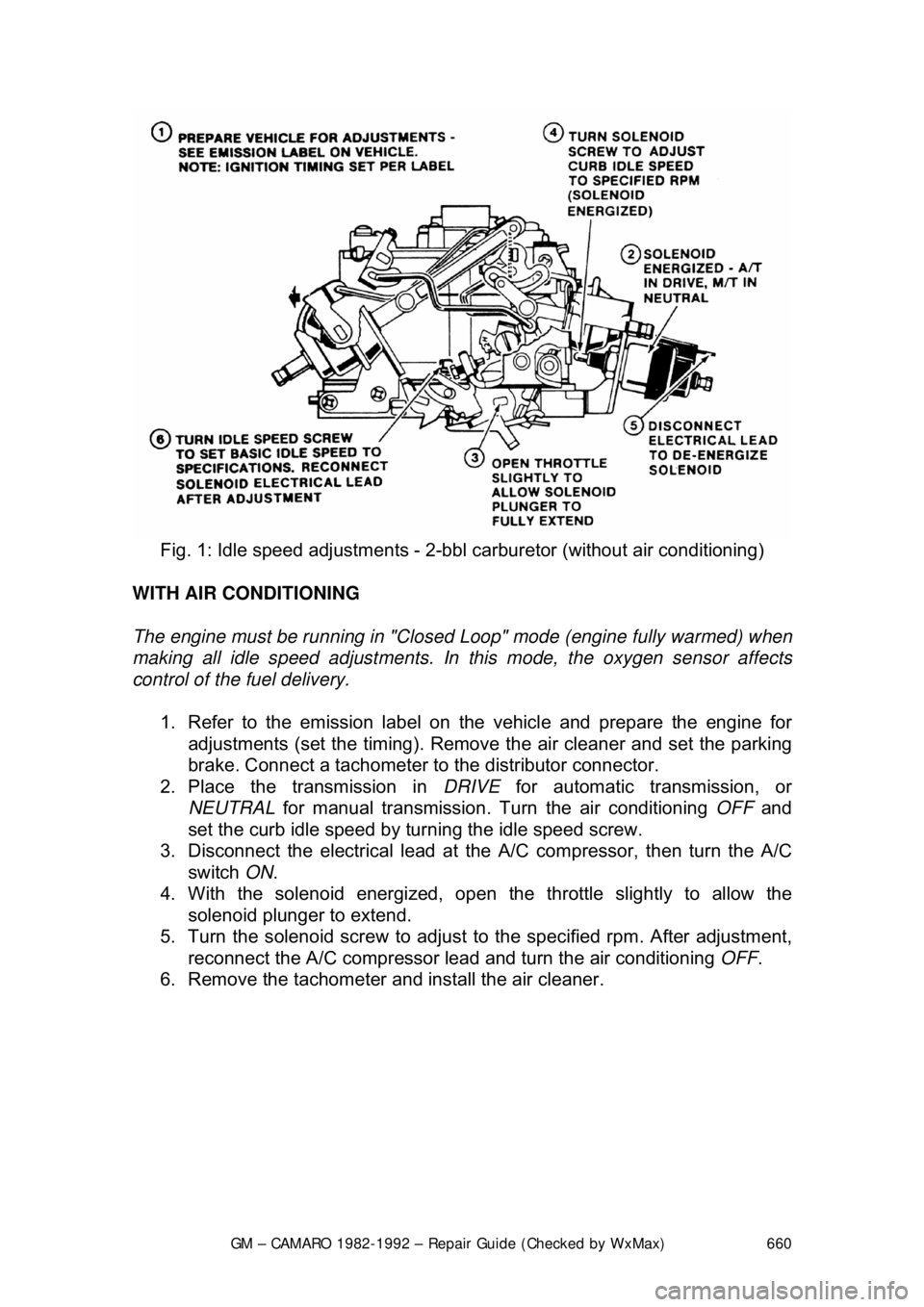
GM – CAMARO 1982-1992 – Repair Guide (Checked by WxMax) 660
Fig. 1: Idle speed adjustm ents - 2-bbl carburetor (without air conditioning)
WITH AIR CONDITIONING
The engine must be running in "Closed Loop" mode (engine fully warmed) when
making all idle speed adjustments. In this mode, the oxygen sensor affects
control of the fuel delivery.
1. Refer to the emission label on the vehicle and prepare the engine for
adjustments (set the timing). Remove the air cleaner and set the parking
brake. Connect a tachometer to the distributor connector.
2. Place the transmission in DRIVE for automatic transmission, or
NEUTRAL for manual transmission. Tu rn the air conditioning OFF and
set the curb idle speed by turning the idle speed screw.
3. Disconnect the electrical lead at the A/C compressor, then turn the A/C
switch ON.
4. With the solenoid e nergized, open the throttle slightly to allow the
solenoid plunger to extend.
5. Turn the solenoid screw to adjust to the specified rpm. After adjustment,
reconnect the A/C compressor lead and turn the air conditioning OFF.
6. Remove the tachometer and install the air cleaner.
Page 661 of 875
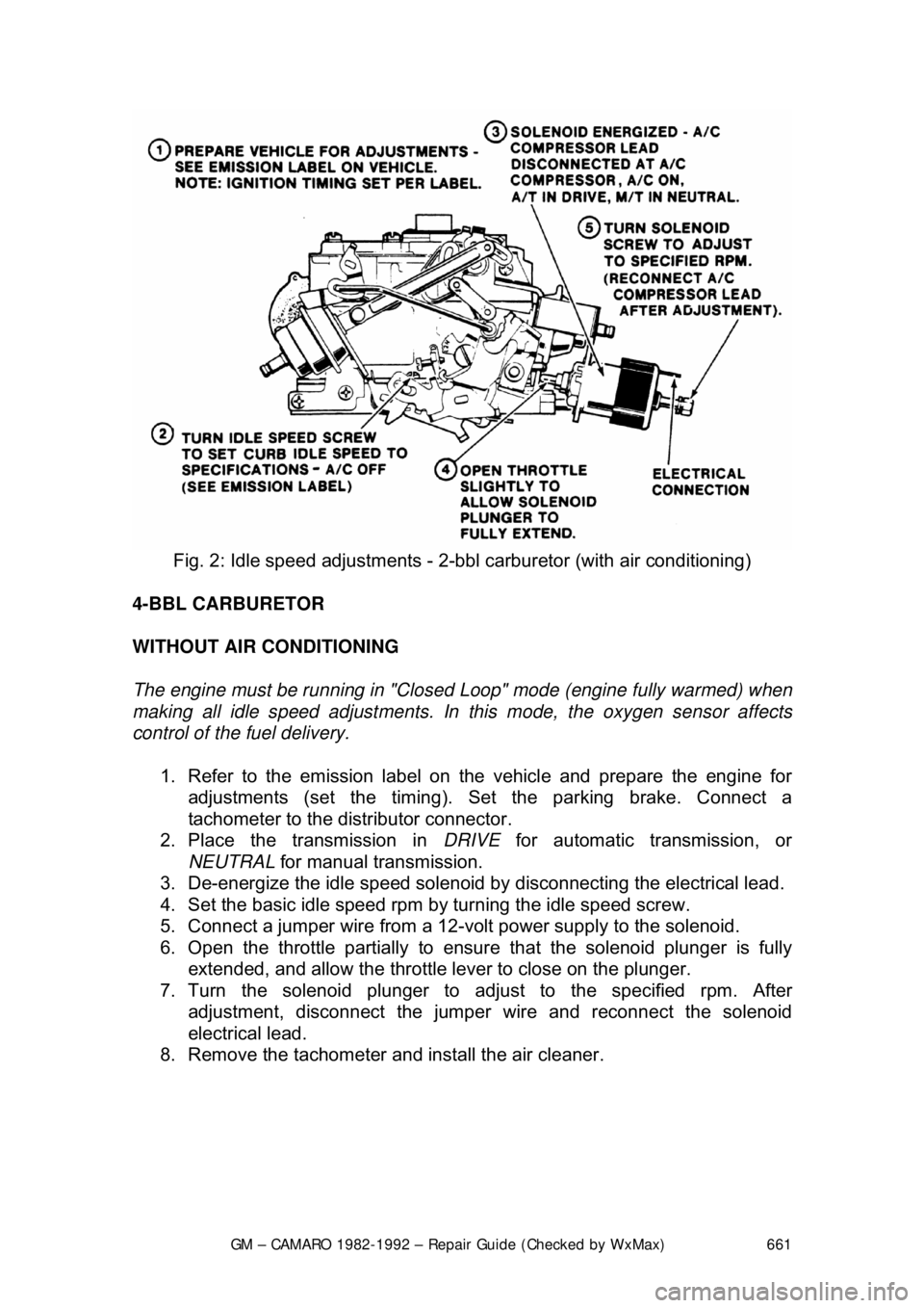
GM – CAMARO 1982-1992 – Repair Guide (Checked by WxMax) 661
Fig. 2: Idle speed adjustm ents - 2-bbl carburetor (with air conditioning)
4-BBL CARBURETOR
WITHOUT AIR CONDITIONING
The engine must be running in "Closed Loop" mode (engine fully warmed) when
making all idle speed adjustments. In this mode, the oxygen sensor affects
control of the fuel delivery.
1. Refer to the emission label on the vehicle and prepare the engine for
adjustments (set the timing). Se t the parking brake. Connect a
tachometer to the dist ributor connector.
2. Place the transmission in DRIVE for automatic transmission, or
NEUTRAL for manual transmission.
3. De-energize the idle speed solenoid by disconnecting the electrical lead.
4. Set the basic idle speed rpm by turning the idle speed screw.
5. Connect a jumper wire from a 12-vo lt power supply to the solenoid.
6. Open the throttle partially to ensure that the solenoid plunger is fully
extended, and allow the throttle lever to close on the plunger.
7. Turn the solenoid plunger to adj ust to the specified rpm. After
adjustment, disconnect the jumper wire and reconnect the solenoid
electrical lead.
8. Remove the tachometer and install the air cleaner.
Page 662 of 875
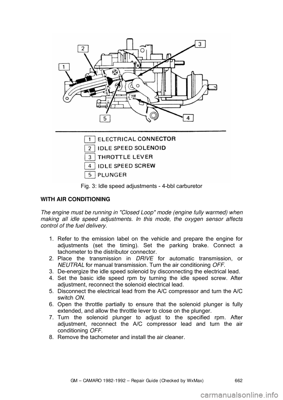
GM – CAMARO 1982-1992 – Repair Guide (Checked by WxMax) 662
Fig. 3: Idle speed adjustm ents - 4-bbl carburetor
WITH AIR CONDITIONING
The engine must be running in "Closed Loop" mode (engine fully warmed) when
making all idle speed adjustments. In this mode, the oxygen sensor affects
control of the fuel delivery.
1. Refer to the emission label on the vehicle and prepare the engine for
adjustments (set the timing). Se t the parking brake. Connect a
tachometer to the dist ributor connector.
2. Place the transmission in DRIVE for automatic transmission, or
NEUTRAL for manual transmission. Tu rn the air conditioning OFF.
3. De-energize the idle speed solenoid by disconnecting the electrical lead.
4. Set the basic idle speed rpm by turning the idle speed screw. After
adjustment, reconnect the solenoid electrical lead.
5. Disconnect the electrical lead from the A/C compressor and turn the A/C
switch ON.
6. Open the throttle partially to ensure that the solenoid plunger is fully
extended, and allow the throttle lever to close on the plunger.
7. Turn the solenoid plunger to adj ust to the specified rpm. After
adjustment, reconnect the A/C co mpressor lead and turn the air
conditioning OFF.
8. Remove the tachometer and install the air cleaner.
Page 666 of 875

GM – CAMARO 1982-1992 – Repair Guide (Checked by WxMax) 666
FUEL SYSTEM
BASIC FUEL SYSTEM DIAGNOSIS
When there is a problem star ting or driving a vehicle, two of the most important
checks involve the ignition and the fuel systems. The questions most mechanics
attempt to answer first, "is there spark?" an d "is there fuel?" will often lead to
solving most basic problems. For igni tion system diagnosis and testing, please
refer to the information on engine electr ical components and ignition systems
found earlier in this repair guide. If the ignition system checks out (there is
spark), then you must determine if the f uel system is operating properly (is there
fuel?).
CARBURETED FUEL SYSTEM
MECHANICAL FUEL PUMP
All fuel pumps used on carbureted V6 and V8 engines are of the diaphragm
type and are serviced by replacement onl y. No adjustments or repairs are
possible. The fuel pump is mounted on th e left front (V6) and right front (V8) of
the engine.
The fuel pumps are also equipped with vapor return lines for purposes of
emission control and to reduce vapor lock. All pumps are operated by an
eccentric on the camshaft. On V6 an d V8 engines, a pushrod between the
camshaft eccentric and the fuel pump operates the pump.
REMOVAL & INSTALLATION
When disconnecting the fuel pump outlet fitting, always use two wrenches to
avoid twisting the line.
1. Disconnect the fuel in take and outlet lines at the pump, then plug the
pump intake line.
2. Remove the two pump mounting bol ts and lockwashers; remove the
pump and its gasket.
3. If the pump pushrod is to be remo ved from the V8, remove the two
adapter bolts and lockwashers, then re move the adapter and its gasket.
4. Install the fuel pump with a new gasket reversing the removal procedure.
Coat the mating surfaces with sealer.
5. Connect the fuel lines and check for leaks.