exhaust CHEVROLET CAMARO 1982 Repair Guide
[x] Cancel search | Manufacturer: CHEVROLET, Model Year: 1982, Model line: CAMARO, Model: CHEVROLET CAMARO 1982Pages: 875, PDF Size: 88.64 MB
Page 483 of 875
GM – CAMARO 1982-1992 – Repair Guide (Checked by WxMax) 483
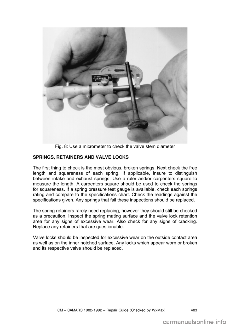
Fig. 8: Use a micrometer to check the valve stem diameter
SPRINGS, RETAINERS AND VALVE LOCKS
The first thing to check is the most obv ious, broken springs. Next check the free
length and squareness of each spring. If applicable, insure to distinguish
between intake and exhaust springs. Use a ruler and/or carpenters square to
measure the length. A car penters square should be used to check the springs
for squareness. If a spring pressure test gauge is available, check each springs
rating and compare to the specifications chart. Check the readings against the
specifications given. Any springs that fa il these inspections should be replaced.
The spring retainers rarely need replacing, however they should still be checked
as a precaution. Inspect the spring mating surface and the valve lock re\
tention
area for any signs of excessive wear. Also check for any signs of cracking.
Replace any retainers t hat are questionable.
Valve locks should be inspected for exce ssive wear on the outside contact area
as well as on the inner notched surface. Any locks which appear worn or broken
and its respective valve should be replaced.
Page 487 of 875
GM – CAMARO 1982-1992 – Repair Guide (Checked by WxMax) 487
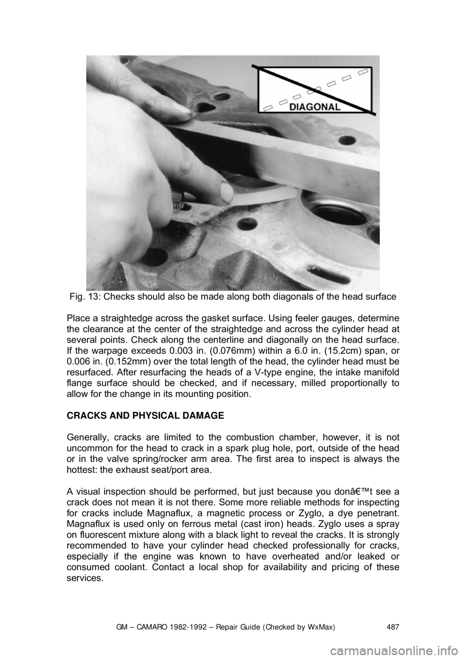
Fig. 13: Checks should also be made al ong both diagonals of the head surface
Place a straightedge across the gasket surf ace. Using feeler gauges, determine
the clearance at the cent er of the straightedge and across the cylinder head at
several points. Check along the centerli ne and diagonally on the head surface.
If the warpage exceeds 0.003 in. (0.076mm) within a 6.0 in. (15.2cm) span, or
0.006 in. (0.152mm) over the total length of the head, the cylinder head must be
resurfaced. After resurfacing the heads of a V-type engine, the intake manifold
flange surface should be checked, and if necessary, milled proportionally to
allow for the change in its mounting position.
CRACKS AND PHYSICAL DAMAGE
Generally, cracks are limited to the comb ustion chamber, however, it is not
uncommon for the head to crack in a s park plug hole, port, outside of the head
or in the valve spring/rocker arm area. The first area to inspect is always the
hottest: the exhaust seat/port area.
A visual inspection should be perform ed, but just because you don’t see a
crack does not mean it is not there. Some more reliable methods for inspecting
for cracks include Magnaflux, a magnetic process or Zyglo, a dye penetrant.
Magnaflux is used onl y on ferrous metal (cast iron) heads. Zyglo uses a spray
on fluorescent mixture along with a black light to reveal the cracks. It is strongly
recommended to have your cylinder head c hecked professionally for cracks,
especially if the engine was known to have overheated and/or leaked or
consumed coolant. Contact a local shop fo r availability and pricing of these
services.
Page 541 of 875
GM – CAMARO 1982-1992 – Repair Guide (Checked by WxMax) 541
EVAPORATIVE EMISS
ION CONTROLS
OPERATION
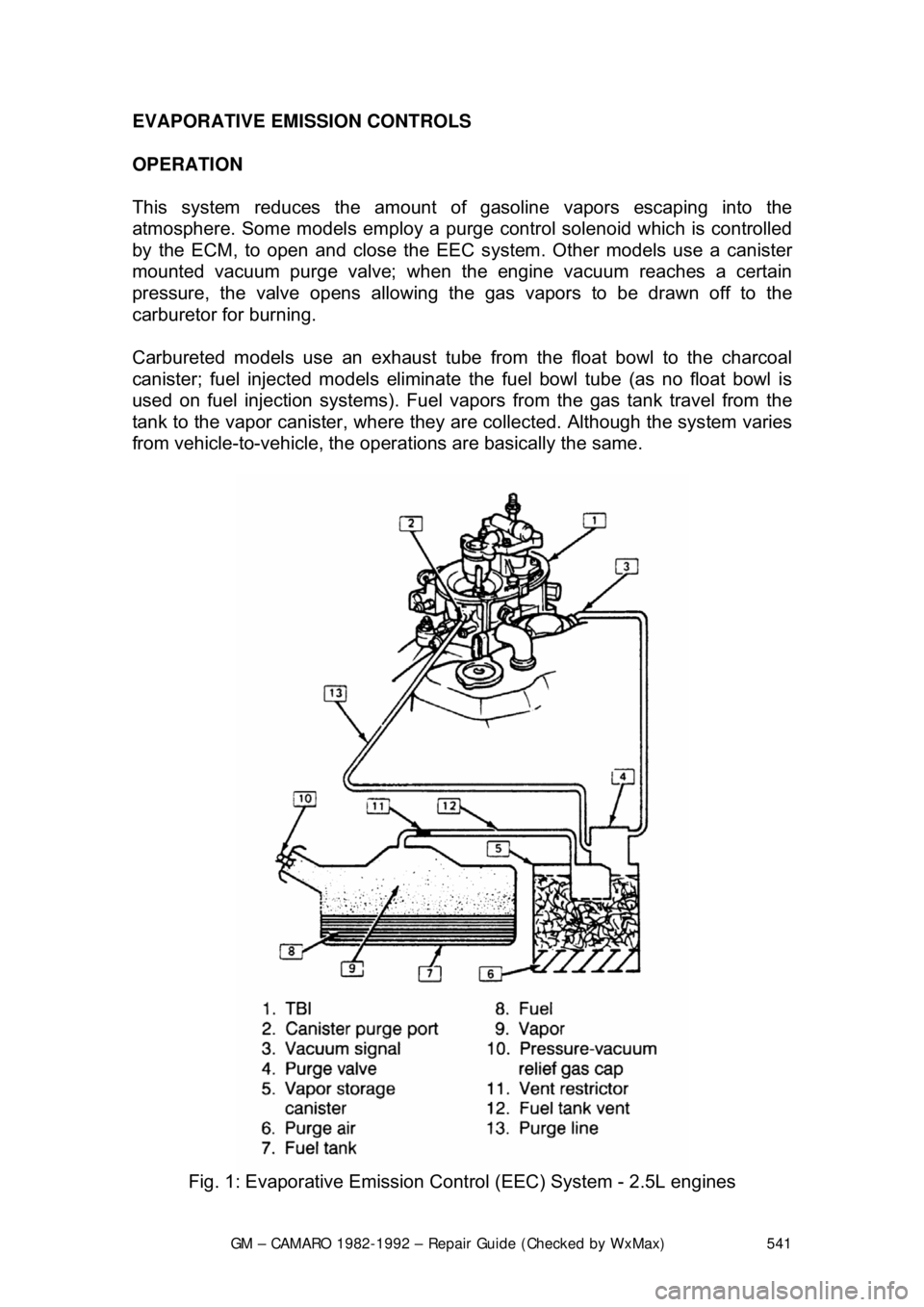
This system reduces the amount of gasoline vapors escaping into the
atmosphere. Some models em ploy a purge control solenoid which is controlled
by the ECM, to open and close the EE C system. Other models use a canister
mounted vacuum purge valve; when the engine vacuum reaches a certain
pressure, the valve opens allowing the gas vapors to be drawn off to the
carburetor for burning.
Carbureted models use an exhaust tube fr om the float bowl to the charcoal
canister; fuel injected models eliminate the fuel bowl tube (as no float bowl is
used on fuel injection systems). Fuel vapor s from the gas tank travel from the
tank to the vapor canister , where they are collected. Although the system varies
from vehicle-to-vehicle, the operat ions are basically the same.
Fig. 1: Evaporative Emission Cont rol (EEC) System - 2.5L engines
Page 547 of 875

GM – CAMARO 1982-1992 – Repair Guide (Checked by WxMax) 547
EXHAUST GAS RECIRCULATION (EGR) SYSTEM
OPERATION
All models are equipped with
this system, which consists of a metering valve, a
vacuum line to the carburet or or intake manifold, and cast-in exhaust passages
in the intake manifold. The EGR valve is controlled by vacuum, which opens
and closes in response to the vacuum signals to admit exhaust gases into the
air/fuel mixture. The exhaust gases lower peak combustion temperatures,
reducing the formation of NOx. The valve is closed at idle and wide open
throttle, but is open between the two extreme positions.
There are actually four types of EGR systems: Ported, Positive Back-Pressure,
Negative Backpressure and Digital. The pr inciple of all the systems are the
same; the only difference is in the me thod used to control how the EGR valve
opens.
Too much EGR flow at idle, cruise or during cold operation may result in the
engine stalling after cold start, the engine stalling at idle after deceleration,
vehicle surge during cruise and rough idle . If the EGR valve is always open, the
vehicle may not idle. Too little or no EGR flow allows combustion temperatures
to rise, which could result in spar k knock (detonation), engine overheating
and/or emission test failure.
A Thermal Vacuum Switch (TVS) or vacuum control solenoid may sometimes\
be used in combination with the EGR va lve. The TVS will close off vacuum
during cold operation. A va cuum control solenoid uses Pulse Width Modulation
(PWM) to turn the solenoid ON and OFF numerous times a second and varies
the amount of ON time (pulse width) to vary the amount of ported vacuum
supplied the EGR valve.
PORTED VALVE
In the ported system, the amount of ex haust gas admitted into the intake
manifold depends on a ported vacuum signal. A ported vacuum signal is one
taken from the carburetor above the th rottle plates; thus, the vacuum signal
(amount of vacuum) is dependent on how far the throttle plates are opened.
When the throttle is closed (idle or dec eleration) there is no vacuum signal.
Thus, the EGR valve is closed, and no exhaust gas enters the intake mani\
fold.
As the throttle is opened, a vacuum is produced, which opens the EGR valve,
admitting exhaust gas into the intake manifold.
POSITIVE BACKPRE SSURE VALVE
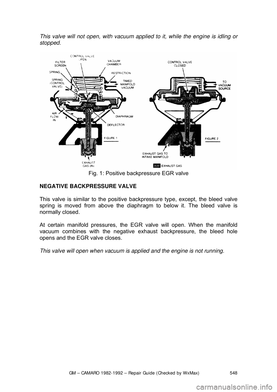
This valve operates the same as the ported, except, it has an internal air bleed
that acts as a vacuum regulator. T he bleed valve controls the amount of
vacuum inside the vacuum chamber duri ng operation. When the valve receives
sufficient exhaust backpressure through the hollow shaft, it closes the bleed; at
this point the EGR valve opens.
Page 548 of 875
GM – CAMARO 1982-1992 – Repair Guide (Checked by WxMax) 548
This valve will not open, wit
h vacuum applied to it, while the engine is idling or
stopped.
Fig. 1: Positive backpressure EGR valve
NEGATIVE BACKPRESSURE VALVE
This valve is similar to the positive ba ckpressure type, except, the bleed valve
spring is moved from above the diaphragm to below it. The bleed valve is
normally closed.
At certain manifold pressures, the EG R valve will open. When the manifold
vacuum combines with the negative exhaust backpressure, the bleed hole
opens and the EGR valve closes.
This valve will open when vacuum is applied and the engine is not running.
Page 552 of 875
GM – CAMARO 1982-1992 – Repair Guide (Checked by WxMax) 552
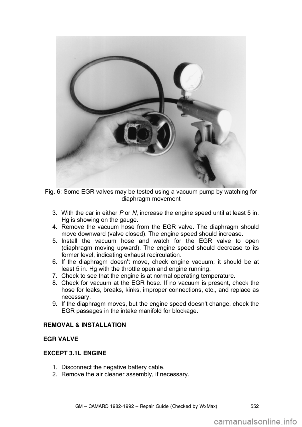
Fig. 6: Some EGR valves may be test ed using a vacuum pump by watching for
diaphragm movement
3. With the car in either P or N, increase the engine speed until at least 5 in.
Hg is showing on the gauge.
4. Remove the vacuum hose from t he EGR valve. The diaphragm should
move downward (valve closed). The engine speed should increase.
5. Install the vacuum hose and watch for the EGR valve to open (diaphragm moving upward). The engine speed should decrease to its
former level, indicating exhaust recirculation.
6. If the diaphragm doesn't move, c heck engine vacuum; it should be at
least 5 in. Hg with the throttle open and engine running.
7. Check to see that the engine is at normal operating temperature.
8. Check for vacuum at the EGR hose. If no vacuum is present, check the
hose for leaks, breaks, kinks, improper connections, etc., and replace as
necessary.
9. If the diaphragm move s, but the engine speed doesn't change, check the
EGR passages in the intake manifold for blockage.
REMOVAL & INSTALLATION
EGR VALVE
EXCEPT 3.1L ENGINE 1. Disconnect the negative battery cable.
2. Remove the air cleaner assembly, if necessary.
Page 553 of 875
GM – CAMARO 1982-1992 – Repair Guide (Checked by WxMax) 553
If equipped with the 5.0L (VIN F) and 5.7L
(VIN 8) engines with Tuned Port
Injection (TPI), it will be necessary to remove the intake plenum to gain access
to the EGR valve.
3. Tag and disconnect the necessary hos es and wiring to gain access to
the EGR valve.
4. Remove the EGR valve retaining bolts.
5. Remove the EGR valve. Discard the gasket.
6. Buff the exhaust deposits from the mounting surface and around the
valve using a wire wheel.
7. Remove deposits from the valve outlet.
8. Clean the mounting surfaces of the intake manifold and valve assembly.
To install: 9. Install a new EGR gasket.
10. Install the EGR valve to the manifold.
11. Install the retaining bolts.
12. Connect the wiring and hoses.
13. Install the air cleaner assembly.
14. Connect the negative battery cable.
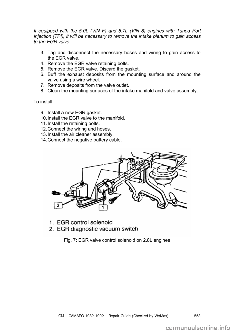
Fig. 7: EGR valve control solenoid on 2.8L engines
Page 559 of 875
GM – CAMARO 1982-1992 – Repair Guide (Checked by WxMax) 559
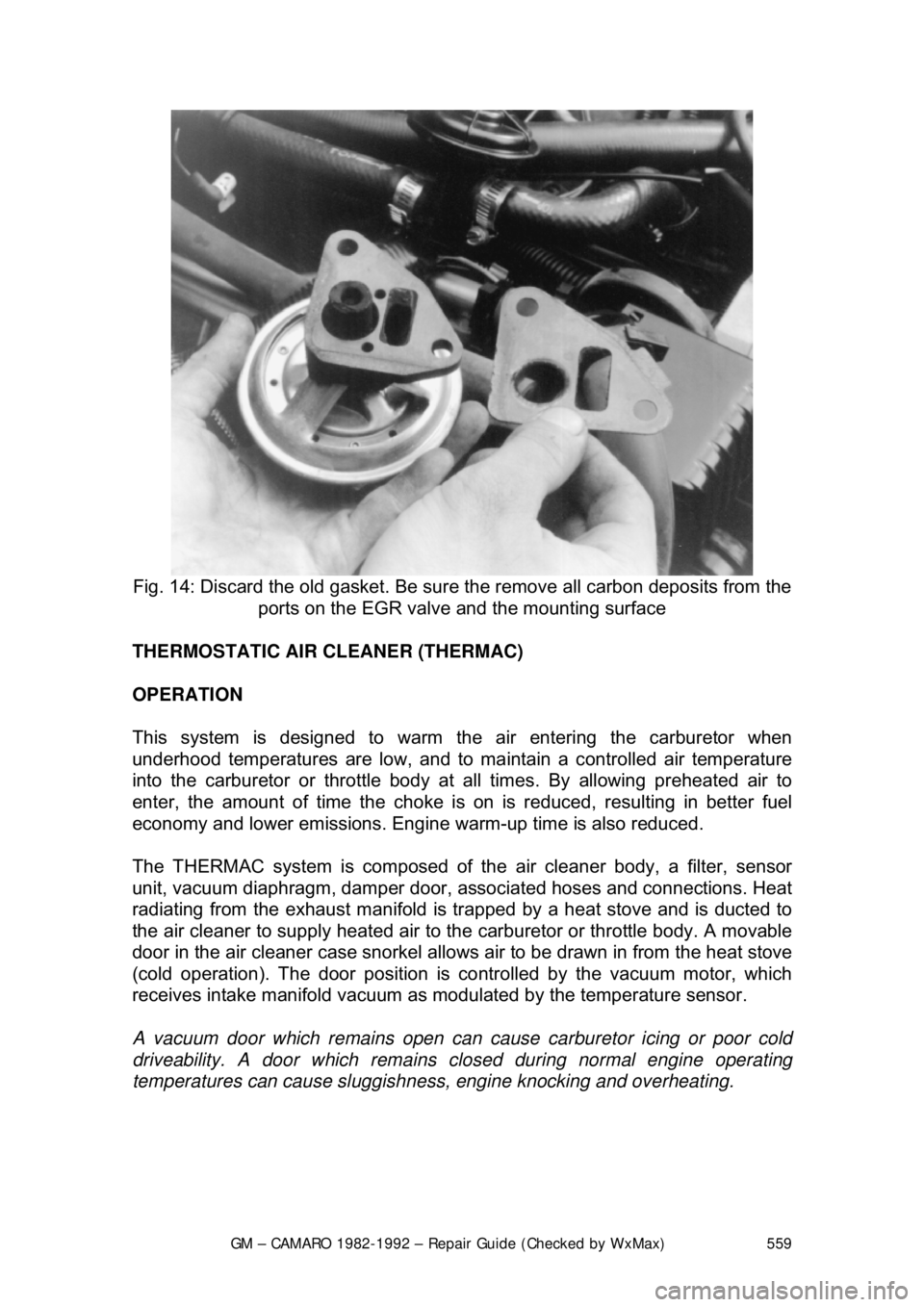
Fig. 14: Discard the old gasket. Be sure the remove all carbon deposits from the
ports on the EGR valve and the mounting surface
THERMOSTATIC AIR CLEANER (THERMAC)
OPERATION
This system is designed to warm the air entering the carburetor when
underhood temperatures are low, and to ma intain a controlled air temperature
into the carburetor or throttle body at all times. By allowing preheated air to
enter, the amount of time t he choke is on is reduced, resulting in better fuel
economy and lower emissions. Engine warm-up time is also reduced.
The THERMAC system is composed of th e air cleaner body, a filter, sensor
unit, vacuum diaphragm, damper door, a ssociated hoses and connections. Heat
radiating from the exhaust manifold is tr apped by a heat stove and is ducted to
the air cleaner to supply heated air to t he carburetor or throttle body. A movable
door in the air cleaner case snorkel allows air to be drawn in from the heat stove
(cold operation). The door position is co ntrolled by the vacuum motor, which
receives intake manifold vacuum as modulated by the temperature sensor.
A vacuum door which remain s open can cause carburetor icing or poor cold
driveability. A door which remains clos ed during normal engine operating
temperatures can cause sluggishne ss, engine knocking and overheating.
Page 562 of 875

GM – CAMARO 1982-1992 – Repair Guide (Checked by WxMax) 562
Air is injected into either the exhaust
port(s), the exhaust manifold(s) or the
catalytic converter by an engine driven ai r pump. The system is in operation at
all times and will bypass air only mom entarily during deceleration and at high
speeds. The bypass function is performed by the air control valve, while the
check valve protects the air pump by pr eventing any backflow of exhaust gases.
The AIR system helps r educe HC and CO content in the exhaust gases by
injecting air into the exhaust ports dur ing cold engine operation. This air
injection also helps the catalytic conv erter to reach the proper temperature
quicker during warmup. When the engine is warm (Closed Loop), the AIR
system injects air into the beds of a th ree-way converter to lower the HC and
the CO content in the exhaust.
The system utilizes the following components:
1. An engine driven AIR pump.
2. AIR Control valves (Air Control, Air Switching).
3. Air flow and control hoses.
4. Check valves.
5. A dual-bed, three-way catalytic converter.
6. A deceleration back-fire control valve - 2.8L engine only.
The belt driven, vane-type air pump is lo cated at the front of the engine and
supplies clean air to the AIR system fo r purposes already stated. When the
engine is cold, the Electronic Control Module (ECM) energizes an AIR control
solenoid. This allows air to flow to the AIR switching valve. The AIR switching
valve is then energized to direct air to the exhaust ports.
When the engine is warm, the ECM de-energ izes the AIR switching valve, thus
directing the air between the beds of the catalytic converter. This provides
additional oxygen for the ox idizing catalyst in the second bed to decrease HC
and CO, while at the same time keeping oxygen levels low in the first bed,
enabling the reducing catalyst to effect ively decrease the levels of NOx.
If the AIR control valve detects a r apid increase in manifold vacuum
(deceleration), certain operat ing modes (wide open throttle, etc.) or if the ECM
self-diagnostic system detects any problem in the system, air is diverted to the
air cleaner or directly into the atmosphere.
The primary purpose of the EC M's divert mode is to prevent backfiring. Throttle
closure at the beginning of deceleration will temporarily create air/fuel mixtures
which are too rich to burn completely . These mixtures become burnable when
they reach the exhaust if combined with the injection ai r. The next firing of the
engine will ignite this mixt ure causing an exhaust backf ire. Momentary diverting
of the injection air from the exhaust prevents this.
The AIR system check valves and hoses should be checked periodically for any
leaks, cracks or deterioration.
Page 569 of 875
GM – CAMARO 1982-1992 – Repair Guide (Checked by WxMax) 569
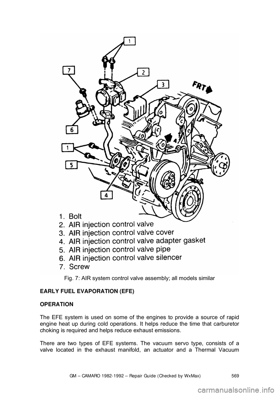
Fig. 7: AIR system control valv e assembly; all models similar
EARLY FUEL EVAPORATION (EFE)
OPERATION
The EFE system is used on some of the engines to provide a source of rapid
engine heat up during cold operations. It hel ps reduce the time that carburetor
choking is required and helps reduce exhaust emissions.
There are two types of EF E systems. The vacuum servo type, consists of a
valve located in the exhaust manifold , an actuator and a Thermal Vacuum