CHEVROLET CAMARO 1982 Repair Guide
Manufacturer: CHEVROLET, Model Year: 1982, Model line: CAMARO, Model: CHEVROLET CAMARO 1982Pages: 875, PDF Size: 88.64 MB
Page 451 of 875
GM – CAMARO 1982-1992 – Repair Guide (Checked by WxMax) 451
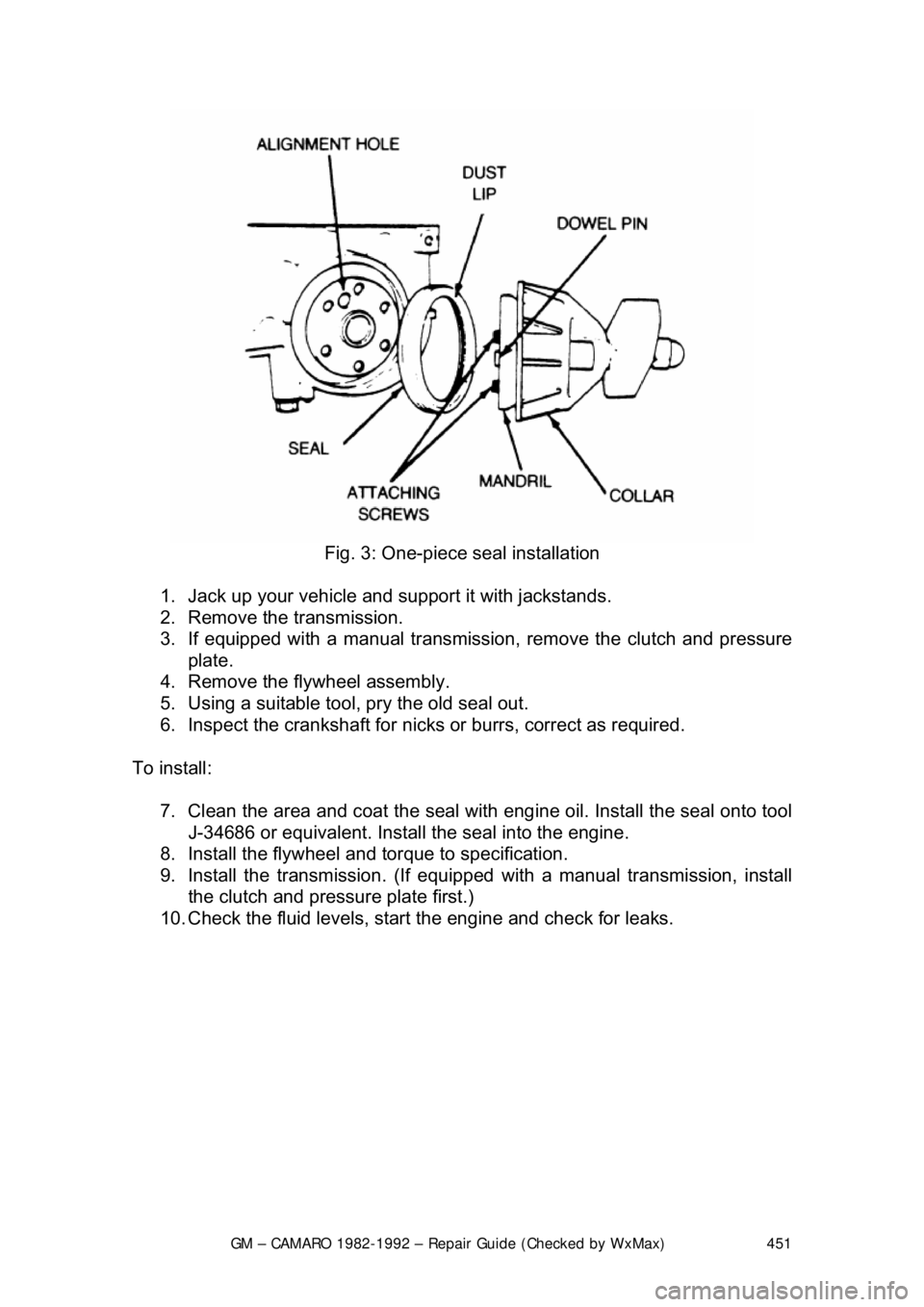
Fig. 3: One-piece seal installation
1. Jack up your vehicle and support it with jackstands.
2. Remove the transmission.
3. If equipped with a manual transmission, remove the clutch and pressure
plate.
4. Remove the flywheel assembly.
5. Using a suitable tool, pry the old seal out.
6. Inspect the crankshaft for nicks or burrs, correct as required.
To install: 7. Clean the area and coat the seal with eng ine oil. Install the seal onto tool
J-34686 or equivalent. Install the seal into the engine.
8. Install the flywheel and torque to specification.
9. Install the transmission. (If equipped with a manual transmission, install
the clutch and pressure plate first.)
10. Check the fluid levels, star t the engine and check for leaks.
Page 452 of 875
GM – CAMARO 1982-1992 – Repair Guide (Checked by WxMax) 452
2-PIECE NEOPRENE SEAL
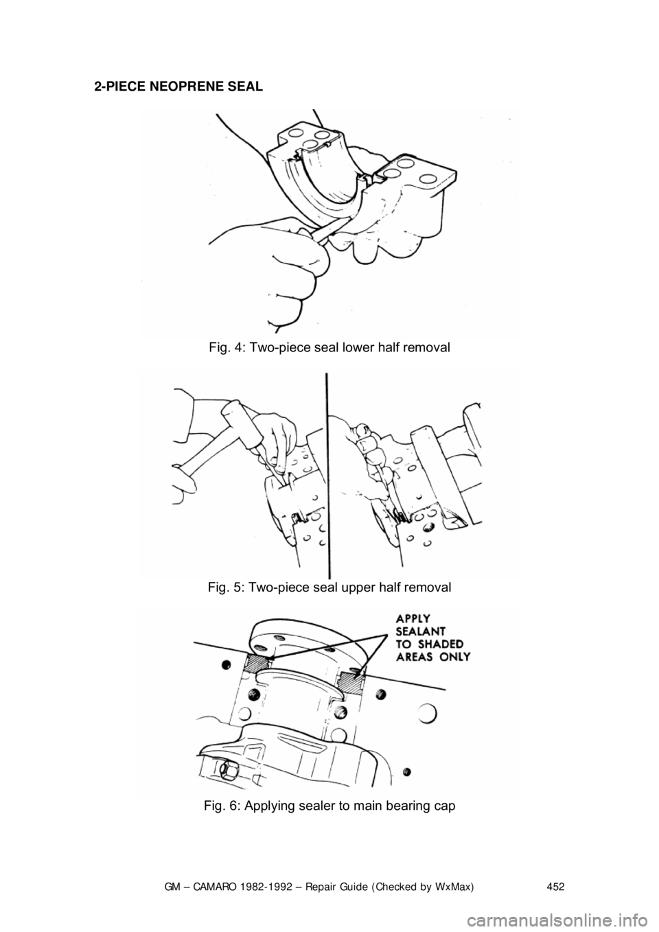
Fig. 4: Two-piece seal lower half removal
Fig. 5: Two-piece seal upper half removal
Fig. 6: Applying sealer to main bearing cap
Page 453 of 875
GM – CAMARO 1982-1992 – Repair Guide (Checked by WxMax) 453
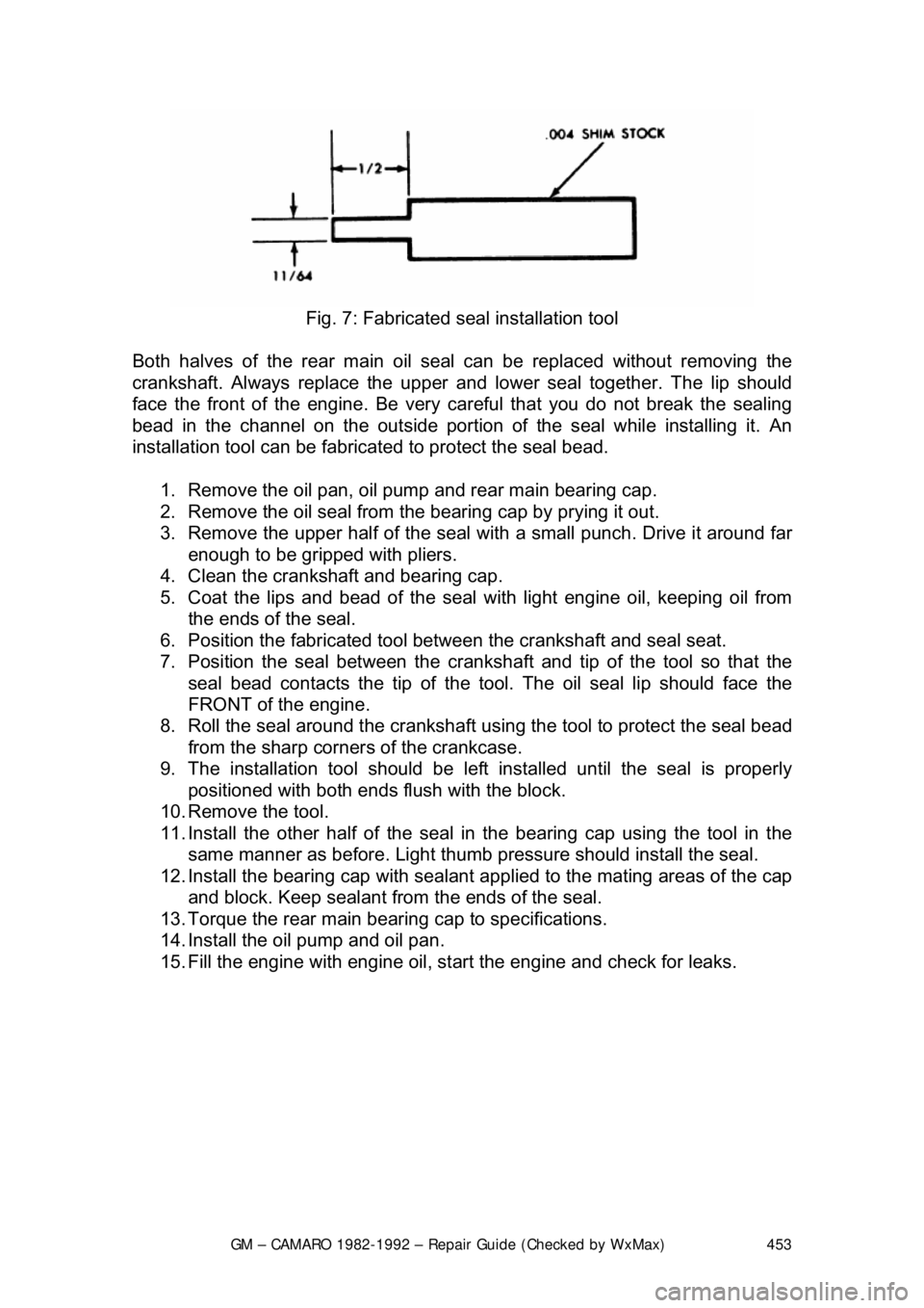
Fig. 7: Fabricated s eal installation tool
Both halves of the rear main oil s eal can be replaced without removing the
crankshaft. Always replace the upper and lower seal together. The lip should
face the front of the engine. Be very ca reful that you do not break the sealing
bead in the channel on the out side portion of the seal while installing it. An
installation tool can be fabricat ed to protect the seal bead.
1. Remove the oil pan, oil pump and rear main bearing cap.
2. Remove the oil seal from the bearing cap by prying it out.
3. Remove the upper half of the seal wit h a small punch. Drive it around far
enough to be gripped with pliers.
4. Clean the crankshaft and bearing cap.
5. Coat the lips and bead of the seal with light engine oil, keeping oil from
the ends of the seal.
6. Position the fabricated tool bet ween the crankshaft and seal seat.
7. Position the seal between the cranks haft and tip of the tool so that the
seal bead contacts the ti p of the tool. The oil seal lip should face the
FRONT of the engine.
8. Roll the seal around the crankshaft us ing the tool to protect the seal bead
from the sharp corner s of the crankcase.
9. The installation tool should be le ft installed until the seal is properly
positioned with both ends fl ush with the block.
10. Remove the tool.
11. Install the other half of the seal in the bearing cap using the tool in the
same manner as before. Light thumb pressure should install the seal.
12. Install the bearing cap with sealant applied to the mating areas of the cap
and block. Keep sealant from the ends of the seal.
13. Torque the rear main bear ing cap to specifications.
14. Install the oil pump and oil pan.
15. Fill the engine with engine oil, st art the engine and check for leaks.
Page 454 of 875
GM – CAMARO 1982-1992 – Repair Guide (Checked by WxMax) 454
ROPE SEAL
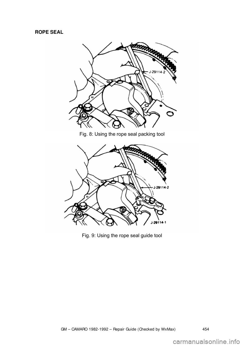
Fig. 8: Using the rope seal packing tool
Fig. 9: Using the rope seal guide tool
Page 455 of 875
GM – CAMARO 1982-1992 – Repair Guide (Checked by WxMax) 455
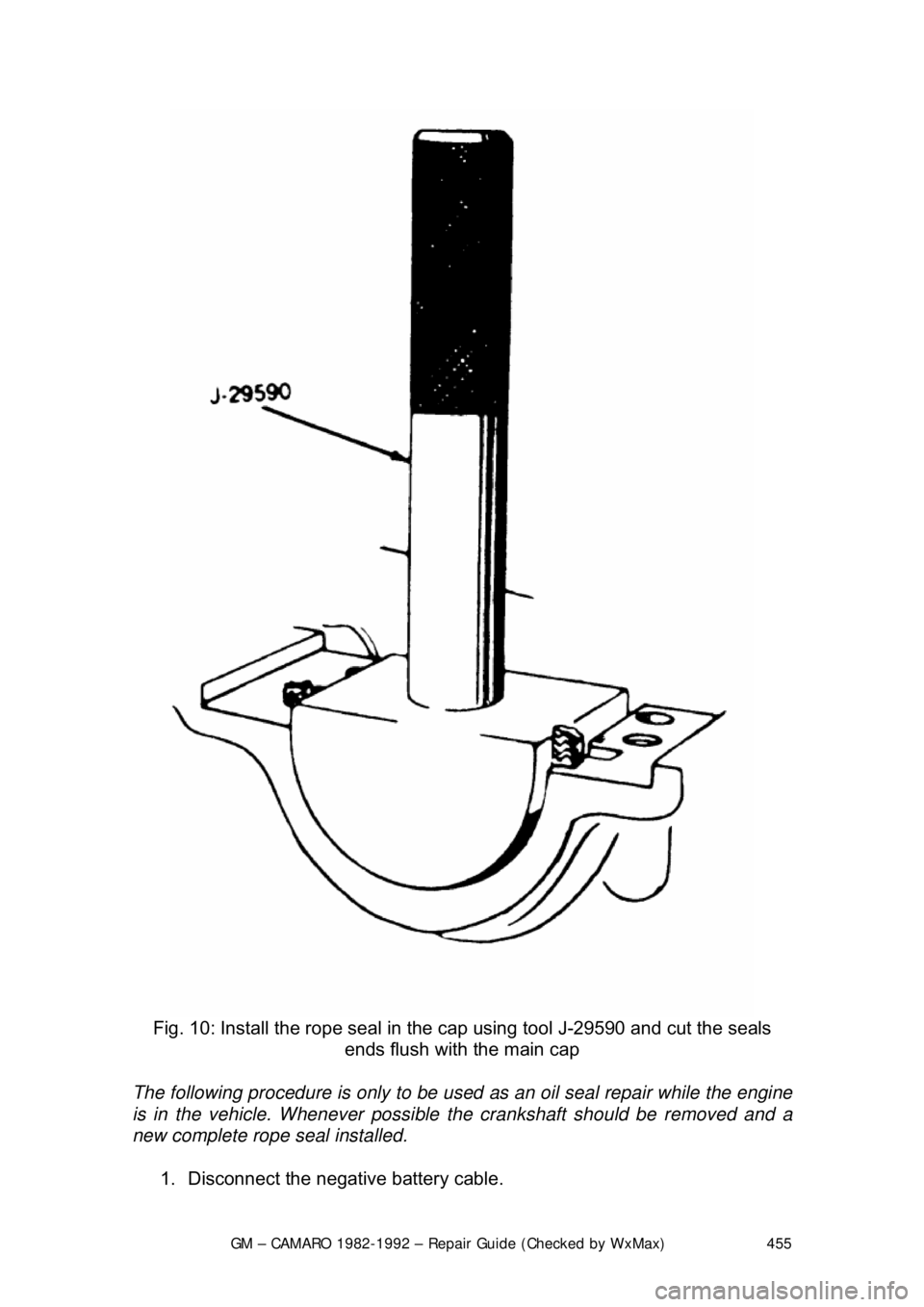
Fig. 10: Install the rope seal in the cap using tool J-29590 and cut the seals
ends flush with the main cap
The following procedure is only to be used as an oil seal repair while the engine
is in the vehicle. Whenever possible the crankshaft should be removed and a
new complete rope seal installed.
1. Disconnect the negative battery cable.
Page 456 of 875

GM – CAMARO 1982-1992 – Repair Guide (Checked by WxMax) 456
2. Drain the engine oil and remove the oil pan.
3. Remove the rear main bearing cap.
4. Insert packing tool J-29114-2 or equi
valent, against 1 end of the seal in
the cylinder block. Drive the old seal gently into the groove until it is
packed tight. This will vary from
1/4 in. (6mm) to 3/4 in. (19mm) depending
on the amount of pack required.
5. Repeat the procedure on t he other end of the seal.
6. Measure the amount the seal wa s driven up on one side and add
1/16 in.
(1.6mm). Using a suitable cutting tool, cut that length from the old seal
removed from the rear main beari ng cap. Repeat the procedure for the
other side. Use the rear main bear ing cap as a holding fixture when
cutting the seal.
7. Install guide tool J-29114-1 or equi valent, onto the cylinder block.
8. Using the packing tool, work the shor t pieces cut in Step 6 into the guide
tool and then pack into the cylinder block. The guide tool and packing
tool are machined to provide a built in stop. Use this procedure for both
sides. It may help to use oil on the short pieces of the rope seal when \
packing them into the cylinder block.
9. Remove the guide tool.
10. Apply Loctite® 414 or equivalent, to the seal groove in the rear main
bearing cap. Within 1 minute, insert a new seal into the groove and push
into place with tool J-29590 until the seal is flush with the block. Cut the
excess seal material with a sharp cu tting tool at the bearing cap parting
line.
11. Apply a thin film of chassis grease to the rope se al. Apply a thin film of
RTV sealant on the bearing cap mati ng surface around the seal groove.
Use the sealer sparingly.
12. Plastigage® the rear main bea ring cap as outlined in MEASURING
REAR MAIN CLEARANCE in this section and check with specification. If
out of specification, check for fr ying of the rope seal which may be
causing the cap to not seat properly.
13. Install all remaining com ponents and inspect for leaks.
FLYWHEEL AND RING GEAR
REMOVAL & INSTALLATION
The ring gear is an integral part of the flywheel and is not replaceable.
1. Remove the transmission.
2. Remove the six bolts attaching t he flywheel to the crankshaft flange.
Remove the flywheel.
3. Inspect the flywheel for cracks, and inspect the ring gear for burrs or
worn teeth. Replace the flywheel if any damage is apparent. Remove
burrs with a mill file.
4. Install the flywheel. Th e flywheel will only attach to the crankshaft in one
position, as the bolt holes are unevenly spaced. Install the bolts and
torque to specification. Tighten bolts in crisscross pattern.
Page 457 of 875
GM – CAMARO 1982-1992 – Repair Guide (Checked by WxMax) 457
EXHAUST SYSTEM
INSPECTION
Safety glasses should be worn at all
times when working on or near the exhaust
system. Older exhaust systems will almost always be covered with loose rust
particles which will shower you when dist urbed. These particles are more than a
nuisance and could injure your eye.
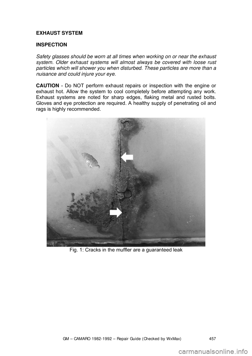
CAUTION - Do NOT perform exhaust repairs or inspection with the engine or
exhaust hot. Allow the system to cool completely before attempting any work.
Exhaust systems are noted for sharp edges , flaking metal and rusted bolts.
Gloves and eye protection ar e required. A healthy supply of penetrating oil and
rags is highly recommended.
Fig. 1: Cracks in the mu ffler are a guaranteed leak
Page 458 of 875
GM – CAMARO 1982-1992 – Repair Guide (Checked by WxMax) 458
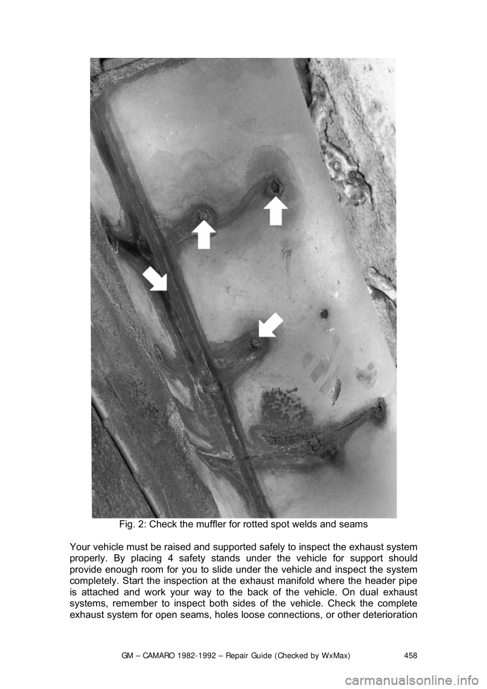
Fig. 2: Check the muffler fo r rotted spot welds and seams
Your vehicle must be rais ed and supported safely to inspect the exhaust system
properly. By placing 4 safety stands under the vehicle for support shoul\
d
provide enough room for you to slide u nder the vehicle and inspect the system
completely. Start the inspection at t he exhaust manifold where the header pipe
is attached and work your way to the back of the vehicle. On dual exhaust
systems, remember to inspect both sides of the vehicle. Check the complete
exhaust system for open seam s, holes loose connections, or other deterioration
Page 459 of 875
GM – CAMARO 1982-1992 – Repair Guide (Checked by WxMax) 459
which could permit exhaust fumes to
seep into the passenger compartment.
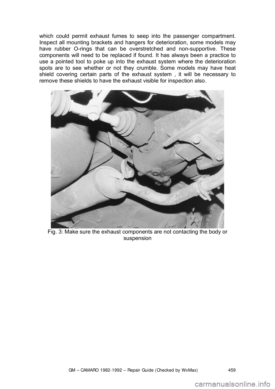
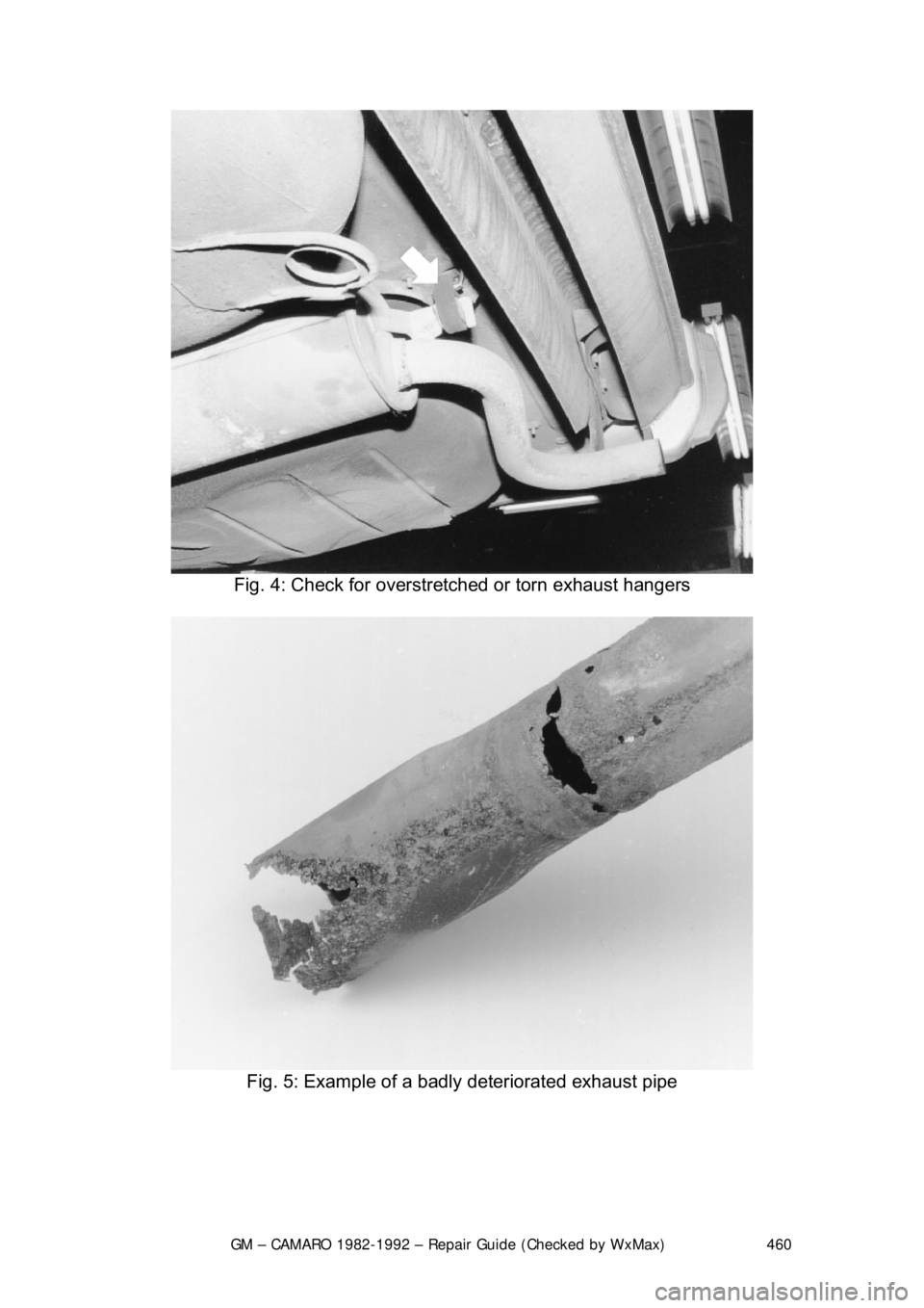
Inspect all mounting brackets and hangers for deterioration, some models may
have rubber O-rings that can be ov erstretched and non-supportive. These
components will need to be replaced if fou nd. It has always been a practice to
use a pointed tool to poke up into the exhaust system where the deterioration
spots are to see whether or not they crumble. Some models may have heat
shield covering certain parts of the ex haust system , it will be necessary to
remove these shields to have the exh aust visible for inspection also.
Fig. 3: Make sure the exhaust co mponents are not contacting the body or
suspension
Page 460 of 875
GM – CAMARO 1982-1992 – Repair Guide (Checked by WxMax) 460
Fig. 4: Check for overstre tched or torn exhaust hangers
Fig. 5: Example of a badl y deteriorated exhaust pipe