CHEVROLET CAMARO 1982 Repair Guide
Manufacturer: CHEVROLET, Model Year: 1982, Model line: CAMARO, Model: CHEVROLET CAMARO 1982Pages: 875, PDF Size: 88.64 MB
Page 441 of 875

GM – CAMARO 1982-1992 – Repair Guide (Checked by WxMax) 441
2. Remove the fan, driv
e belts and water pump pul ley. Remove the valve
cover. Loosen the rocker arms and pivot them, then remove the
pushrods.
3. Remove the oil pump driveshaft and gear assembly. This is located
under a small plate secured by two bol ts near the oil filter. Remove the
spark plugs.
4. Mark the position of the distribut or rotor, housing, and engine block.
Remove the distributor.
5. Remove the valve lifters. They are located behind the pushrod cover.
6. Remove the timing gear cover.
7. Insert a screwdriver through the holes in the ti ming gear and remove the
2 camshaft thrust plate screws.
8. Pull the camshaft and gear assembly out through the front of the engine
block.
When removing the camshaft, be careful not to damage the camshaft bearings.
9. If the camshaft is to be removed from the timing gear, place the assembly in an arbor press and s eparate. CAUTION When removing the
timing gear from the camshaft, the thrust plate must be positioned so that
the woodruff key does not damage it.
To install: 10. To install the timing gear to the camshaft, press the assembly together
and measure the end clearance. T here should be 0.0015-0.0050 in.
(0.038-0.127mm) between the thrust plate and the camshaft.
If the clearance is less than 0.0015 in. (0 .038mm), replace the spacer ring; if
more than 0.0050 in. (0.127mm), replace the thrust ring.
11. Lubricate the camshaft, bearings, and lifters. Slide the camshaft
assembly into the engine and align the timing marks of the camshaft gear
and crankshaft gear.
12. Complete the installation by reversing the removal procedure.
V6 AND V8 ENGINES 1. Remove the engine from the vehicl e or remove all components from the
front of the engine (radi ator, grille, etc.).
2. Remove the timing gear cover and chain.
3. Mark the distributor rotor, housi ng and engine block, then remove the
distributor. Remove the fuel pump and fuel pump pushrod on carbureted
engines.
4. Remove the intake manifold and valve covers. Loosen the rocker arms
and pivot out of way. Remove the pushrods and valve lifters.
5. Remove the oil pump drive.
6. Slide the camshaft toward the front of the engine (be careful not to
damage the camshaft bearings).
Page 442 of 875

GM – CAMARO 1982-1992 – Repair Guide (Checked by WxMax) 442
To install:
7. Lubricate all parts. Slide the ca mshaft onto the camshaft bearings.
8. Install the fuel pump and fuel pump pushrod.
9. Install the distributor and align all matchmarks.
10. Install the oil pump drive.
11. Install the valve lifters, pushrods and rocker arms.
12. Install the intake manifold and valve covers.
13. Install the timing and timing chain cover.
14. Install the radiator.
15. Fill the cooling syst em, start the engine and check for leaks.
BEARING
REMOVAL & INSTALLATION
It is recommended for a machine shop to perform these procedures.
To remove the camshaft bearings, the ca mshaft lifters, flywheel, rear camshaft
expansion plug, and cranks haft must be removed.
Camshaft bearings can be replaced wi th engine completely or partially
disassembled. To replace bearings without complete disassembly remove the
camshaft and crankshaft leaving cylinder heads attached and pistons in place.
Before removing crankshaft, tape threads of connecting rod bolts to prevent
damage to crankshaft. Fasten connecting rods against sides of engine so they
will not be in the way while replacing camshaft bearings.
If excessive wear is indicated, or if the engine is being completely rebuilt,
camshaft bearings should be replaced as follows: Drive the camshaft rear plug
from the block. Assemble the removal puller with its shoulder on the bearing to
be removed. Gradually tighten the puller nut until bearing is removed. Remove
remaining bearings, leaving the front and rear for last. To remove front and rear
bearings, reverse position of the tool, so as to pull the bearings in toward the
center of the block. Leave the tool in th is position, pilot the new front and rear
bearings on the installer, and pull them into position as follows:
• 4 cylinder engines: Ensure oil holes are properly aligned.
• V6 engines: Ensure the rear and intermediate bearing oil holes are
aligned between the 2 and 3 o'clock po sitions and the front bearing oil
holes are at 1:00 and between 2 and 3 o'clock positions.
• V8 engines: Ensure the No. 1 (f ront) camshaft bearing holes are an
equal distance from the 6 o'clock pos ition. The No. 2 through 4 inner
bearing holes must be posit ioned at the 5 o'clock position towards the left
side (drivers) of the engine, even wit h the bottom of the cylinder bore.
The No. 5 bearing oil holes must be positioned at 12 o'clock.
Return the tool to its original position and pull remaining bearings into position.
Page 443 of 875

GM – CAMARO 1982-1992 – Repair Guide (Checked by WxMax) 443
Ensure that oil holes are properly al
igned. Replace camshaft rear plug, and
stake it into position to aid retention.
INSPECTION
CAMSHAFT LOBE LIFT
Check the lift of each lobe in consecutiv e order and make a note of the reading.
1. Remove the fresh air inlet tube a nd the air cleaner. Remove the heater
hose and crankcase ventilation hoses. Remove valve rocker arm
cover(s).
2. Remove the rocker arm stud nut or fulcrum bolts, fulcrum seat and rocker
arm.
3. Make sure the pushrod is in the valve tappet socket. Install a dial indicator so that the actuating poin t of the indicator is in the pushrod
socket (or the indicator ball socket adapter tool is on the end of the
pushrod) and in the same plane as the pushrod movement.
4. Disable the ignition and fuel systems.
5. Install a remote starter switch. Crank the engine with the ignition and fuel
system disabled. Turn the crankshaft ov er until the tappet is on the base
circle of the camshaft lobe. At this position, the pushrod will be in its
lowest position.
6. Zero the dial indicator. Continue to rotate the crankshaft slowly until the
pushrod is in the fully raised position.
7. Compare the total lift recorded on the dial indicator with the specification
shown on the Camshaft Specification chart.
To check the accuracy of the original in dicator reading, continue to rotate the
crankshaft until the indicator reads zero. If the lift on any lobe is below specified
wear limits listed, the ca mshaft and the valve tappet operating on the worn
lobe(s) must be replaced.
8. Install the rocker arm, fulcrum seat and stud nut or fulcrum bolts. Adjust
the valves, if required (r efer to the valves procedure in this section).
9. Install the valve rocker arm cover(s) and the air cleaner.
CAMSHAFT END PLAY
On all gasoline V8 engi nes, prying against the aluminum-nylon camshaft
sprocket, with the valve train load on t he camshaft, can break or damage the
sprocket. Therefore, the rocker arm adj usting nuts must be backed off, or the
rocker arm and shaft assembly must be loosened sufficiently to free the
camshaft. After checking the camshaft e nd play, check the valve clearance.
Adjust if required (refer to procedure in this section).
1. Push the camshaft toward the rear of the engine. Install a dial indicator or
equivalent so that the indicator point is on the camshaft sprocket
attaching screw.
Page 444 of 875
GM – CAMARO 1982-1992 – Repair Guide (Checked by WxMax) 444
2. Zero the dial indicator. Positi
on a prybar between the camshaft gear and
the block. Pull the camshaft forwar d and release it. Compare the dial
indicator reading with the specifications.
3. If the end play is excessive, che ck the spacer for correct installation
before it is removed. If the spacer is correctly installed, replace the thrust
plate.
4. Remove the dial indicator.
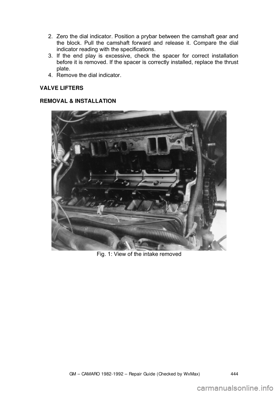
VALVE LIFTERS
REMOVAL & INSTALLATION
Fig. 1: View of the intake removed
Page 445 of 875
GM – CAMARO 1982-1992 – Repair Guide (Checked by WxMax) 445
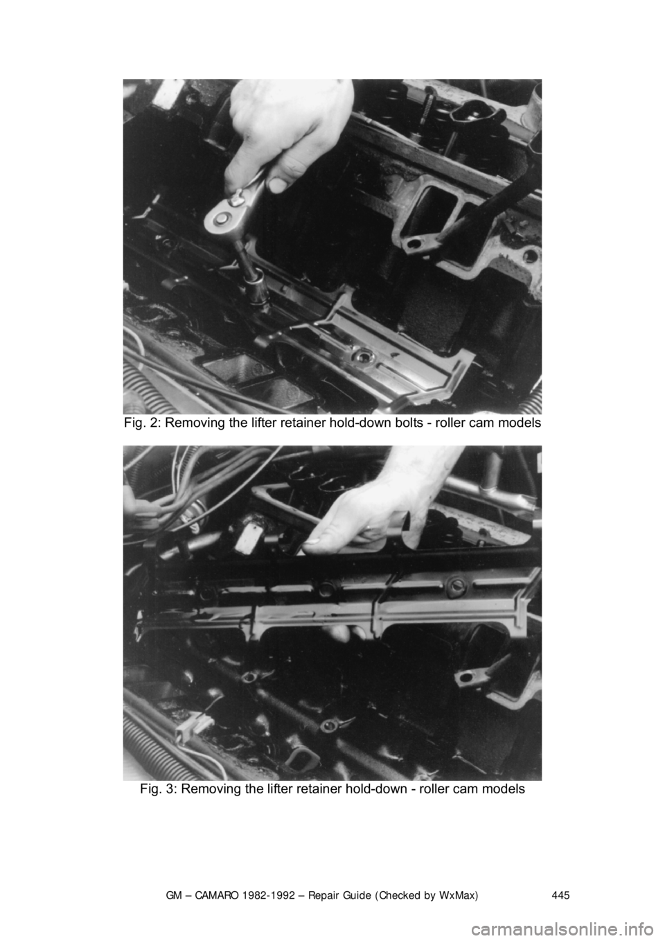
Fig. 2: Removing the lifter retainer hold-down bolts - roller cam models
Fig. 3: Removing the lifter retai ner hold-down - roller cam models
Page 446 of 875
GM – CAMARO 1982-1992 – Repair Guide (Checked by WxMax) 446
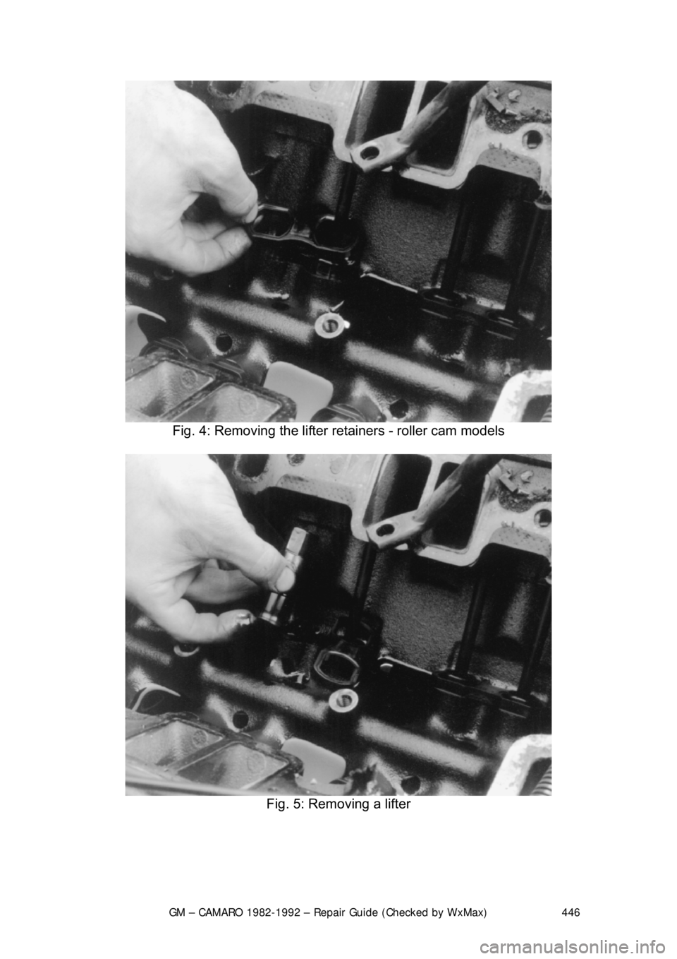
Fig. 4: Removing the lifter re tainers - roller cam models
Fig. 5: Removing a lifter
Page 447 of 875
GM – CAMARO 1982-1992 – Repair Guide (Checked by WxMax) 447
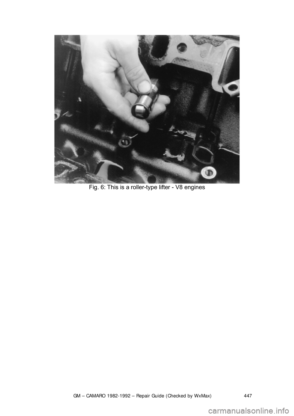
Fig. 6: This is a roller-type lifter - V8 engines
Page 448 of 875
GM – CAMARO 1982-1992 – Repair Guide (Checked by WxMax) 448
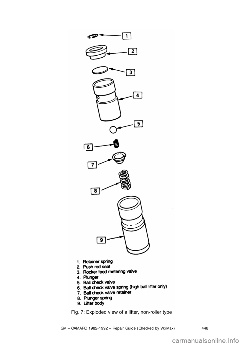
Fig. 7: Exploded view of a lifter, non-roller type
Page 449 of 875

GM – CAMARO 1982-1992 – Repair Guide (Checked by WxMax) 449
1. Remove the intake manifold, valve
cover and pushrod cover (4-cylinder).
Disassemble the rocker arms and remove the pushrods.
2. Remove the lifters. If they are coat ed with varnish, clean with carburetor
cleaning solvent.
3. If installing new lifters or you have disassembled the lifters, they must be
primed before installation. Submer ge the lifters in SAE 10 oil and
carefully push down on the plunger with a
1/8 in. (3mm) drift. Hold the
plunger down (DO NOT pum p), then release the plunger slowly. The lifter
is now primed.
4. Coat the bottoms of the lifters wit h Molykote® before installation. Install
the lifters and pushrods into the e ngine in their original position.
5. Install the rocker arms and adjust the valves. Complete the installation by
reversing the removal procedure.
FREEZE PLUGS
REMOVAL & INSTALLATION
CAUTION - When draining the coolant, keep in mind that cats and dogs are
attracted by the ethylene gl ycol antifreeze, and are quite likely to drink any that
is left in an uncovered container or in puddles on the ground. This will prove
fatal in sufficient quantity. Always drai n the coolant into a sealable container.
Coolant should be reused unless it is contaminated or several years old.
1. Disconnect the negative battery cable.
2. Drain the cooling system.
3. Raise and support the vehicle safely.
4. Remove the coolant drain plug on t he side of the block, if equipped. If not
you can use a punch to put a small ho le in the center of the freeze plug
that is being replaced.
5. Remove all components in order to gain access to the freeze plug(s).
6. Using a punch, tap the bottom corner of the freeze plug to cock it in the
bore. Remove the plug using pliers.
7. Clean the freeze plug hole and c oat the new plug with sealer.
8. Using a suitable tool, install the freeze plug into the block.
9. Connect the negative battery cable, fill the cooling system, start the
engine and check for leaks.
REAR MAIN OIL SEAL
REMOVAL & INSTALLATION
CAUTION - The EPA warns that prol onged contact with used engine oil may
cause a number of skin disorders, incl uding cancer! You should make every
effort to minimize your exposure to used engine oil. Pr otective gloves should be
worn when changing the oil. Wash y our hands and any other exposed skin
areas as soon as possible after exposure to used engine oil. Soap and water, or
waterless hand cleaner should be used.
1-PIECE NEOPRENE SEAL
Page 450 of 875
GM – CAMARO 1982-1992 – Repair Guide (Checked by WxMax) 450
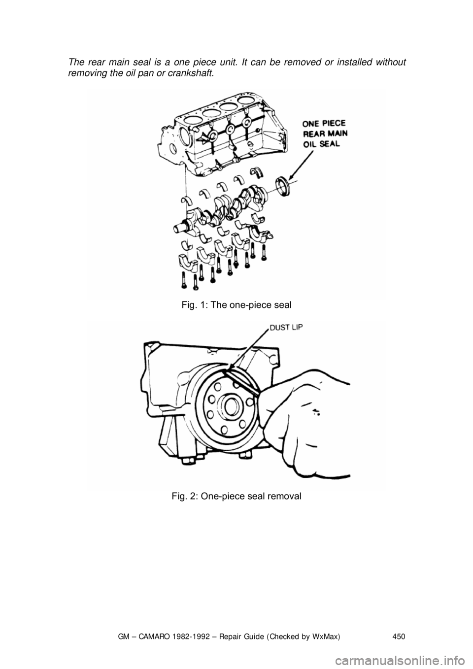
The rear main seal is a
one piece unit. It can be re moved or installed without
removing the oil pan or crankshaft.
Fig. 1: The one-piece seal
Fig. 2: One-piece seal removal