CHEVROLET CAMARO 1982 Repair Guide
Manufacturer: CHEVROLET, Model Year: 1982, Model line: CAMARO, Model: CHEVROLET CAMARO 1982Pages: 875, PDF Size: 88.64 MB
Page 501 of 875
GM – CAMARO 1982-1992 – Repair Guide (Checked by WxMax) 501
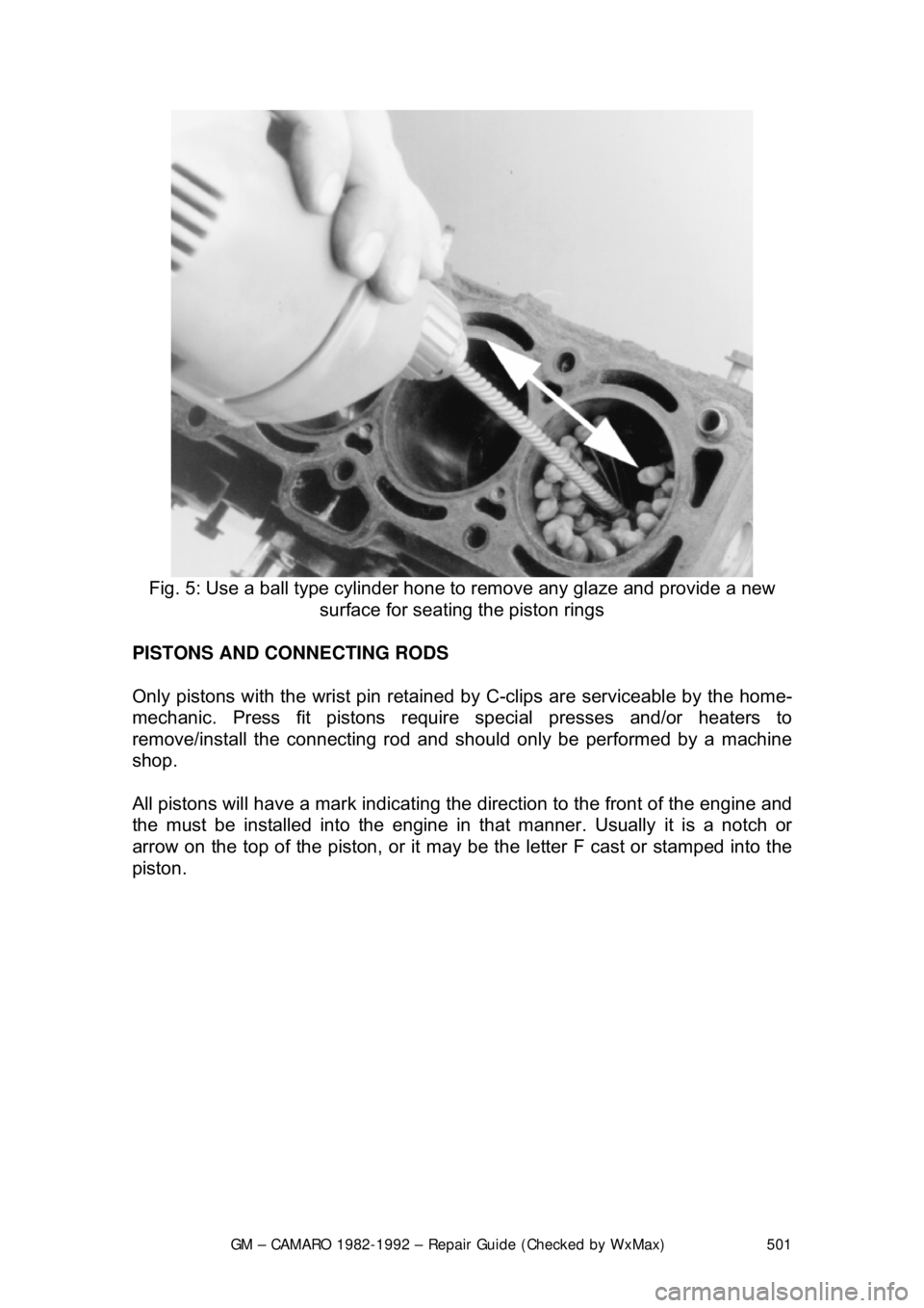
Fig. 5: Use a ball type cylinder hone to remove any glaze and provide a new
surface for seating the piston rings
PISTONS AND CONNECTING RODS
Only pistons with the wrist pin retained by C-clips are serviceable by the home-
mechanic. Press fit pistons require special presses and/or heaters to
remove/install the connecting rod and sh ould only be performed by a machine
shop.
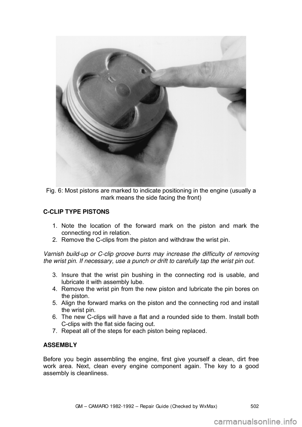
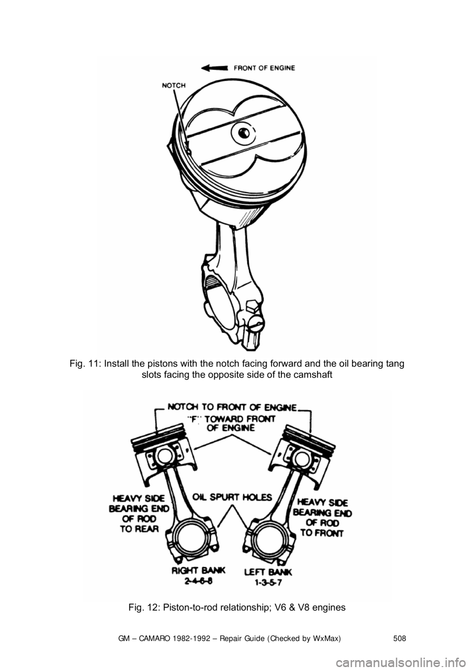
All pistons will have a mark indicating the direction to the front of the engine and
the must be installed into the engine in that manner. Usually it is a notch or
arrow on the top of the piston, or it ma y be the letter F cast or stamped into the
piston.
Page 502 of 875
GM – CAMARO 1982-1992 – Repair Guide (Checked by WxMax) 502
Fig. 6: Most pistons are marked to indica te positioning in the engine (usually a
mark means the side facing the front)
C-CLIP TYPE PISTONS 1. Note the location of the forward mark on the piston and mark the connecting rod in relation.
2. Remove the C-clips from the piston and withdraw the wrist pin.
Varnish build-up or C-clip groove burrs may increase the difficulty of removing
the wrist pin. If necessary, use a punch or drift to carefully tap the wrist pin out.
3. Insure that the wrist pin bushing in the connecting rod is usable, and
lubricate it with assembly lube.
4. Remove the wrist pin from the new piston and lubricate the pin bores on
the piston.
5. Align the forward marks on the pi ston and the connecting rod and install
the wrist pin.
6. The new C-clips will have a flat and a rounded side to them. Install both
C-clips with the flat side facing out.
7. Repeat all of the steps fo r each piston being replaced.
ASSEMBLY
Before you begin assembling the engine, fi rst give yourself a clean, dirt free
work area. Next, clean every engine component again. The key to a good
assembly is cleanliness.
Page 503 of 875

GM – CAMARO 1982-1992 – Repair Guide (Checked by WxMax) 503
Mount the engine block into the engine
stand and wash it one last time using
water and detergent (dishwashing deter gent works well). While washing it,
scrub the cylinder bores with a soft bristl e brush and thoroughly clean all of the
oil passages. Completely dry the engin e and spray the entire assembly down
with an anti-rust solution such as WD-40 or similar product. Take a clean lint-
free rag and wipe up any excess anti-rust solution from the bores, bearing
saddles, etc. Repeat the final cleaning process on the crankshaft. Replace any
freeze or oil galley plugs which we re removed during disassembly.
CRANKSHAFT 1. Remove the main bearing inserts from the block and bearing caps.
2. If the crankshaft main bearing journal s have been refinished to a definite
undersize, install the correct undersize bearing. Be sure that the bearing
inserts and bearing bores are clean. Fo reign material under inserts will
distort bearing and cause failure.
3. Place the upper main bearing inse rts in bores with tang in slot.
The oil holes in the beari ng inserts must be aligned with the oil holes in the
cylinder block.
4. Install the lower main bearing inserts in bearing caps.
5. Clean the mating surfaces of block and rear main bearing cap.
6. Carefully lower the crankshaft into place. Be careful not to damage
bearing surfaces.
7. Check the clearance of each main bearing by using the following
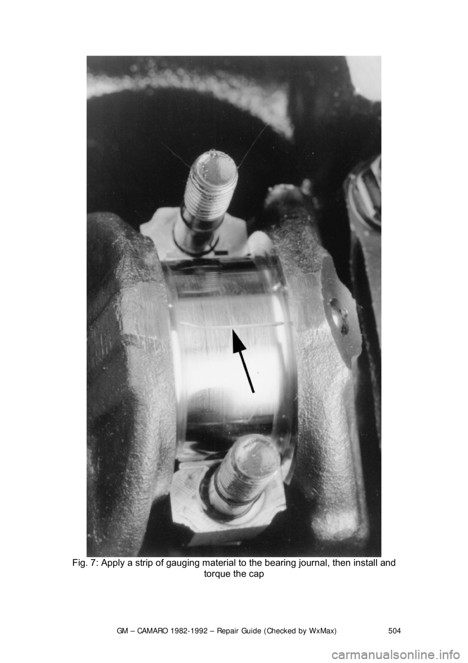
procedure: a. Place a piece of Plastigage® or its equivalent, on bearing surface
across full width of bearing cap and about
1/4 in. off center.
Page 504 of 875
GM – CAMARO 1982-1992 – Repair Guide (Checked by WxMax) 504
Fig. 7: Apply a strip of gauging material to the bearing journal, then install and
torque the cap
Page 505 of 875
GM – CAMARO 1982-1992 – Repair Guide (Checked by WxMax) 505
b. Install cap and tighten bolts to spec
ifications. Do not turn crankshaft
while Plastigage® is in place.
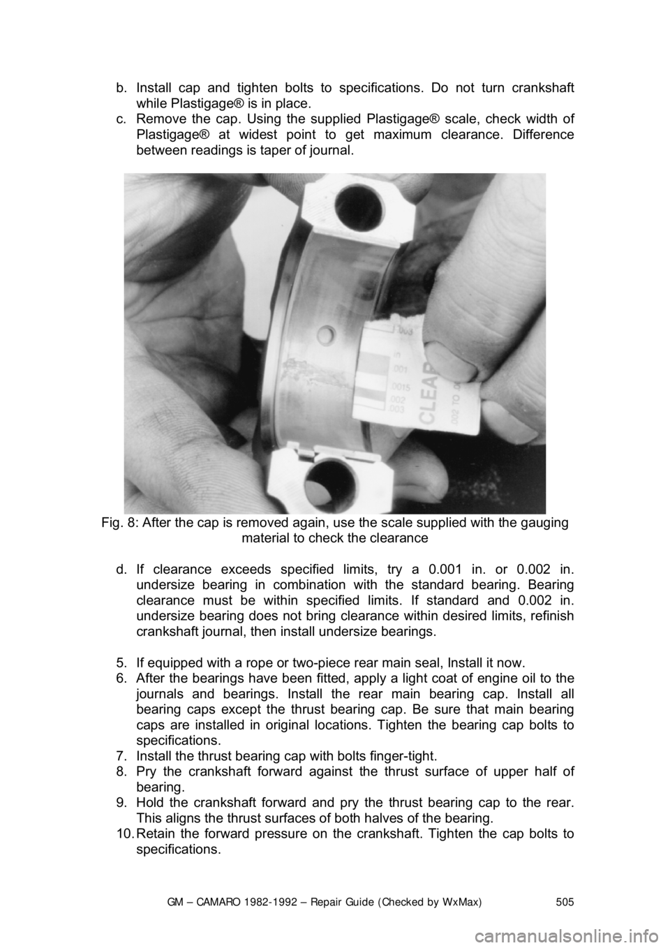
c. Remove the cap. Using the supplie d Plastigage® scale, check width of
Plastigage® at widest point to get maximum clearance. Difference
between readings is ta per of journal.
Fig. 8: After the cap is removed again, use the sca le supplied with the gauging
material to check the clearance
d. If clearance exceeds specified lim its, try a 0.001 in. or 0.002 in.
undersize bearing in combination with the standard bearing. Bearing
clearance must be within specified limits. If standard and 0.002 in.
undersize bearing does not bring clearance within desired limits, refinish
crankshaft journal, then inst all undersize bearings.
5. If equipped with a rope or two-piece r ear main seal, Install it now.
6. After the bearings have been fitted, apply a light coat of engine oil to the
journals and bearings. Install the rear main bearing cap. Install all
bearing caps except the thrust bearing cap. Be sure that main bearing
caps are installed in original locati ons. Tighten the bearing cap bolts to
specifications.
7. Install the thrust bearing cap with bolts finger-tight.
8. Pry the crankshaft forward against the thrust surface of upper half of
bearing.
9. Hold the crankshaft forward and pry the thrust bearing cap to the rear.
This aligns the thrust surfaces of both halves of the bearing.
10. Retain the forward pressure on t he crankshaft. Tighten the cap bolts to
specifications.
Page 506 of 875
GM – CAMARO 1982-1992 – Repair Guide (Checked by WxMax) 506
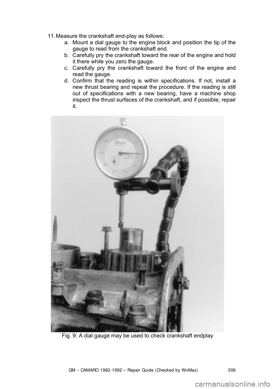
11. Measure the crankshaft end-play as follows:
a. Mount a dial gauge to the engine block and position the tip of the
gauge to read from t he crankshaft end.
b. Carefully pry the crankshaft towa rd the rear of the engine and hold
it there while you zero the gauge.
c. Carefully pry the crankshaft toward the front of the engine and read the gauge.
d. Confirm that the r eading is within specifications. If not, install a
new thrust bearing and repeat the procedure. If the reading is still
out of specifications with a new bearing, have a machine shop
inspect the thrust surfaces of the crankshaft, and if possible, repair
it.
Fig. 9: A dial gauge may be used to check crankshaft endplay
Page 507 of 875
GM – CAMARO 1982-1992 – Repair Guide (Checked by WxMax) 507
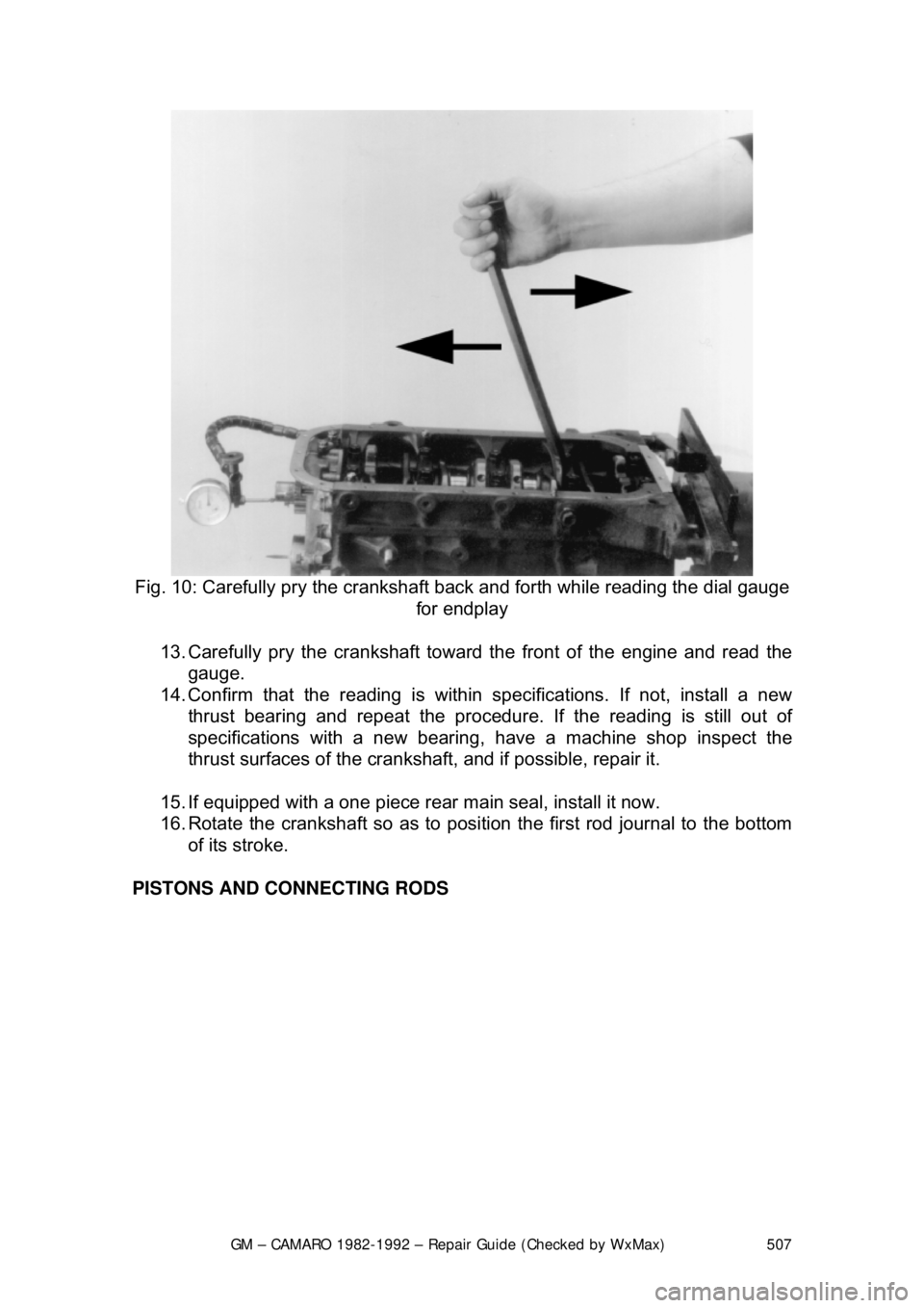
Fig. 10: Carefully pry the crankshaft back and forth while reading the dial gauge
for endplay
13. Carefully pry the crankshaft toward the front of the engine and read the
gauge.
14. Confirm that the reading is within specifications. If not, install a new
thrust bearing and repeat the procedure. If the readi ng is still out of
specifications with a new bearing, have a machine shop inspect the
thrust surfaces of the cranks haft, and if possible, repair it.
15. If equipped with a one piece rear main seal, install it now.
16. Rotate the crankshaft so as to posi tion the first rod journal to the bottom
of its stroke.
PISTONS AND CONNECTING RODS
Page 508 of 875
GM – CAMARO 1982-1992 – Repair Guide (Checked by WxMax) 508
Fig. 11: Install the pistons with the notch facing forward and the oil bearing tang
slots facing the opposite side of the camshaft
Fig. 12: Piston-to-rod relationship; V6 & V8 engines
Page 509 of 875
GM – CAMARO 1982-1992 – Repair Guide (Checked by WxMax) 509
1. Before installing the
piston/connecting rod assembly, oil the pistons,
piston rings and the cylinder walls with light engine oil. Install connecting
rod bolt protectors or rubber hose onto the connecting rod bolts/studs.
Also perform the following: a. Select the proper ring set for the size cylinder bore.
b. Position the ring in the bore in which it is going to be used.
c. Push the ring down into the bor e area where normal ring wear is
not encountered.
d. Use the head of the piston to posi tion the ring in the bore so that
the ring is square with the cyli nder wall. Use caution to avoid
damage to the ring or cylinder bore.
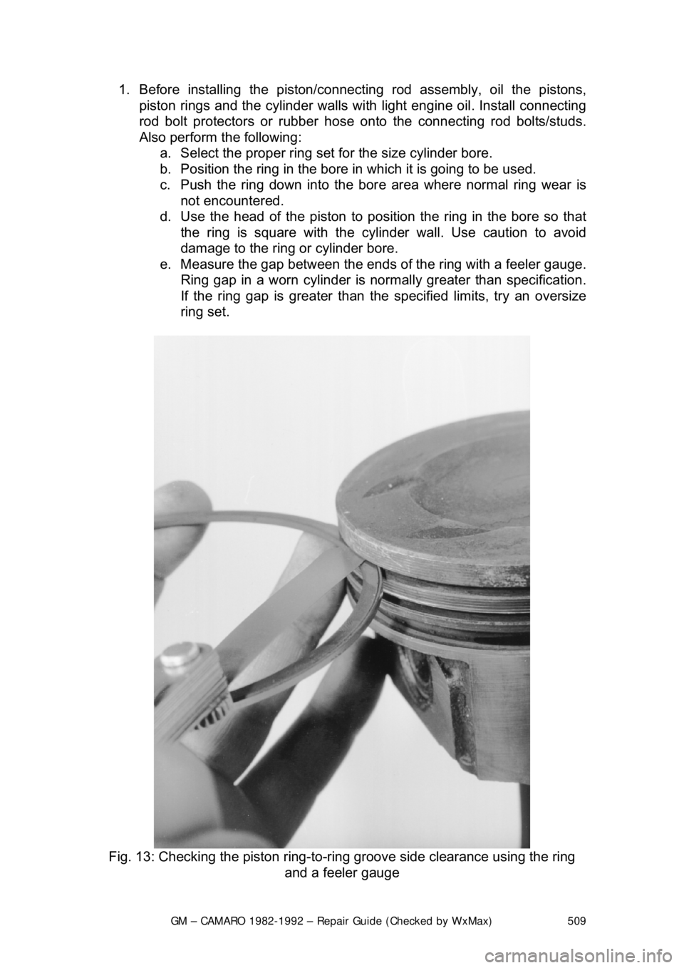
e. Measure the gap betw een the ends of the ring with a feeler gauge.
Ring gap in a worn cylinder is normally greater than specification.
If the ring gap is greater than the specified limits, try an oversize
ring set.
Fig. 13: Checking the piston ring-to-ri ng groove side clearance using the ring
and a feeler gauge
Page 510 of 875
GM – CAMARO 1982-1992 – Repair Guide (Checked by WxMax) 510
f. Check the ring side clearance of the compression rings with a
feeler gauge inserted between the ring and its lower land
according to specification. The gauge should slide freely around
the entire ring circumference wit hout binding. Any wear that
occurs will form a step at the inne r portion of the lower land. If the
lower lands have high steps, t he piston should be replaced.
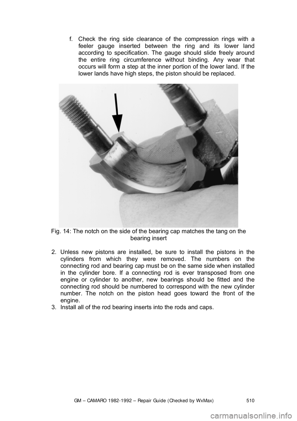
Fig. 14: The notch on the side of t he bearing cap matches the tang on the
bearing insert
2. Unless new pistons are installed, be sure to install the pistons in the
cylinders from which they were removed. The numbers on the
connecting rod and bearing cap must be on the same side when installed
in the cylinder bore. If a connecting rod is ever transposed from one
engine or cylinder to another, new bear ings should be fitted and the
connecting rod should be numbered to correspond with the new cylinder
number. The notch on the piston head goes toward the front of the
engine.
3. Install all of the rod bearing inserts into the rods and caps.