driver CHEVROLET CAMARO SS 2010 Repair Manual
[x] Cancel search | Manufacturer: CHEVROLET, Model Year: 2010, Model line: CAMARO SS, Model: CHEVROLET CAMARO SS 2010Pages: 372, PDF Size: 1.91 MB
Page 257 of 372
If No Steam Is Coming From
The Engine Compartment
If an engine overheat warning is
displayed but no steam can be seen
or heard, the problem may not be too
serious. Sometimes the engine can
get a little too hot when the vehicle:
•Climbs a long hill on a hot day.
•Stops after high-speed driving.
•Idles for long periods in traffic.
•Tows a trailer.
If the overheat warning is displayed
with no sign of steam:
1. Turn the air off.
2. Turn the heater on to the highest
temperature and to the highest
fan speed. Open the windows
as necessary.3. In heavy traffic, let the engine idle
in N (Neutral) while stopped. If it
is safe to do so, pull off the road,
shift to P (Park) or N (Neutral) and
let the engine idle.
If the temperature overheat gage is
no longer in the overheat zone or an
overheat warning no longer displays,
the vehicle can be driven. Continue
to drive the vehicle slow for about
10 minutes. Keep a safe vehicle
distance from the car in front of you.
If the warning does not come back
on, continue to drive normally.
If the warning continues, pull over,
stop, and park the vehicle right away.
If there is no sign of steam, idle
the engine for three minutes while
parked. If the warning is still
displayed, turn off the engine until it
cools down. Also, see “Overheated
Engine Protection Operating Mode”
later in this section.
Power Steering Fluid
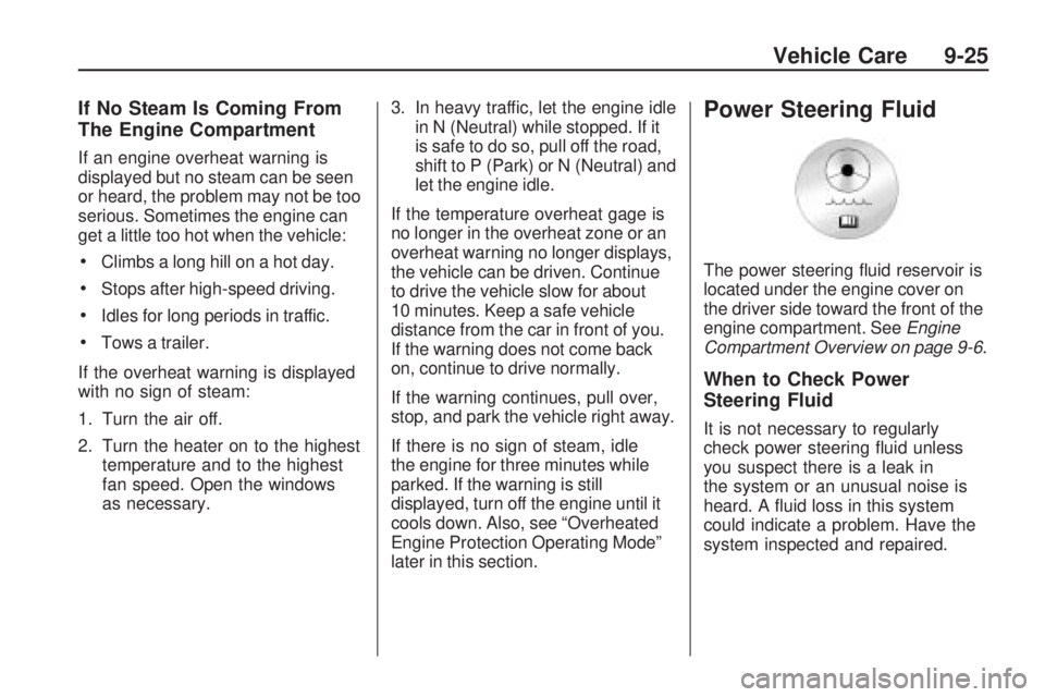
The power steering fluid reservoir is
located under the engine cover on
the driver side toward the front of the
engine compartment. SeeEngine
Compartment Overview on page 9-6.
When to Check Power
Steering Fluid
It is not necessary to regularly
check power steering fluid unless
you suspect there is a leak in
the system or an unusual noise is
heard. A fluid loss in this system
could indicate a problem. Have the
system inspected and repaired.
Vehicle Care 9-25
Page 266 of 372
3. With the latch open, pull the
wiper blade down towards
the windshield far enough to
release it from the J-hooked
end of the wiper arm.
4. Remove the wiper blade.
Allowing the wiper blade arm to
touch the windshield when no
wiper blade is installed could
damage the windshield. Any
damage that occurs would not be
covered by the vehicle warranty.
Do not allow the wiper blade arm
to touch the windshield.
5. Reverse steps 1 through 3 for
wiper blade replacement.Headlamp Aiming
The headlamp aiming system has
been preset at the factory.
If the vehicle is damaged in an
accident, the aim of the headlamps
may be affected and adjustment
may be necessary.
It is recommended that a
dealer/retailer adjust the headlamps.
To re-aim the headlamps yourself,
use the following procedure.
The vehicle should be properly
prepared as follows:
•The vehicle should be placed so
the headlamps are 7.6 m (25 ft)
from a light colored wall.
•The vehicle must have all four
tires on a level surface which
is level all the way to the wall.
•The vehicle should be placed so
it is perpendicular to the wall or
other flat surface.
•The vehicle should not have any
snow, ice, or mud on it.
•The vehicle should be fully
assembled and all other
work stopped while headlamp
aiming is being performed.
•The vehicle should be normally
loaded with a full tank of fuel and
one person or 75 kg (160 lbs)
sitting on the driver’s seat.
•Tires should be properly inflated.
Headlamp aiming is done with the
vehicle’s low-beam headlamps.
The high-beam headlamps will be
correctly aimed if the low-beam
headlamps are aimed properly.
9-34 Vehicle Care
Page 277 of 372
Instrument Panel Fuse
Block
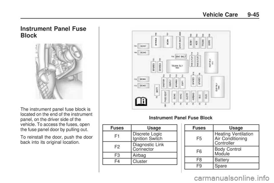
The instrument panel fuse block is
located on the end of the instrument
panel, on the driver side of the
vehicle. To access the fuses, open
the fuse panel door by pulling out.
To reinstall the door, push the door
back into its original location.
FusesUsage
F1 Discrete Logic
Ignition Switch
F2 Diagnostic Link
Connector
F3 Airbag
F4 ClusterFuses Usage
F5 Heating Ventilation
Air Conditioning
Controller
F6 Body Control
Module
F8 Battery
F9 Spare
Instrument Panel Fuse Block
Vehicle Care 9-45
Page 278 of 372

Fuses Usage
F10 Spare
F11 Spare
F12 Spare
F13 Display
F14OnStar
®Universal
Hands Free Phone
F15Body Control
Module 3
F16Body Control
Module 4
F17 Power Outlet 1
F18 Power Outlet 2
F19Steering Wheel
Controls Backlight
F20 Spare
F21 Spare
F22 Spare
F23 Trunk
F24Automatic Occupant
Sensing
Fuses Usage
F25Body Control
Module 1
F27Body Control
Module 8
F28 Spare
F29Body Control
Module 5
F30Body Control
Module 7
Circuit
BreakersUsage
CB7 Passenger Seat
CB26 Driver Seat
Relays Usage
K10Retained Accessory
Power
K605 Not Used
K609 Trunk
Rear Compartment
Fuse Block
The rear compartment fuse block is
located on the right side of the trunk
behind a cover. Remove the six
convenience net retainers, the rear
sill plate, and the two passenger side
trim retainers, then swing the trim out
of the way.
9-46 Vehicle Care
Page 289 of 372
Please note that the TPMS
is not a substitute for proper tire
maintenance, and it is the driver’s
responsibility to maintain correct tire
pressure, even if under-inflation
has not reached the level to trigger
illumination of the TPMS low tire
pressure telltale.
Your vehicle has also been
equipped with a TPMS malfunction
indicator to indicate when the system
is not operating properly. The TPMS
malfunction indicator is combined
with the low tire pressure telltale.
When the system detects a
malfunction, the telltale will flash
for approximately one minute and
then remain continuously illuminated.
This sequence will continue upon
subsequent vehicle start-ups as
long as the malfunction exists.
When the malfunction indicator is
illuminated, the system may not
be able to detect or signal low
tire pressure as intended. TPMS
malfunctions may occur for a varietyof reasons, including the installation
of replacement or alternate tires or
wheels on the vehicle that prevent
the TPMS from functioning properly.
Always check the TPMS malfunction
telltale after replacing one or more
tires or wheels on your vehicle to
ensure that the replacement or
alternate tires and wheels allow
the TPMS to continue to function
properly.
SeeTire Pressure Monitor
Operation on page 9-57for
additional information.
Federal Communications
Commission (FCC) and
Industry and Science Canada
SeeRadio Frequency Statement
(US, Can) on page 12-15for
information regarding Part 15
of the Federal Communications
Commission (FCC) Rules and
RSS-210/211 of Industry and
Science Canada.
Tire Pressure Monitor
Operation
This vehicle may have a Tire
Pressure Monitor System (TPMS).
The TPMS is designed to warn the
driver when a low tire pressure
condition exists. TPMS sensors are
mounted onto each tire and wheel
assembly, excluding the spare tire
and wheel assembly, if the vehicle
has one. The TPMS sensors monitor
the air pressure in the vehicle’s tires
and transmits the tire pressure
readings to a receiver located in
the vehicle.
Using the Driver Information
Center (DIC), the driver can also
check tire pressure levels using the
DIC. For additional information and
details about the DIC operation and
displays seeTire Messages on
page 4-36.
Vehicle Care 9-57
Page 292 of 372

TPMS Sensor Matching
Process
Each TPMS sensor has a unique
identification code. Any time you
replace one or more of the TPMS
sensors or rotate your vehicle’s tires,
the identification codes need to be
matched to the new tire/wheel
position. The sensors are matched
to the tire/wheel positions in the
following order: driver side front tire,
passenger side front tire, passenger
side rear tire, and driver side rear
tire using a TPMS diagnostic tool.
See your dealer/retailer for service.
The TPMS sensors can also be
matched to each tire/wheel position
by increasing or decreasing the
tire’s air pressure. If increasing the
tire’s air pressure, do not exceed
the maximum inflation pressure
indicated on the tire’s sidewall.
To decrease the tire’s air-pressure
use the pointed end of the valve
cap, a pencil-style air pressure
gage, or a key.You have two minutes to match
the first tire/wheel position, and
five minutes overall, to match all
four tire/wheel positions. If it takes
longer than two minutes, to match
the first tire and wheel, or more than
five minutes to match all four tire
and wheel positions, the matching
process stops and you need to
start over.
The TPMS matching process is
outlined below:
1. Set the parking brake.
2. Turn the ignition switch to
ON/RUN with the engine off.
3. Go to the TPM vehicle
information screen on the DIC.
SeeDriver Information Center
(DIC) on page 4-27. Press set to
relearn the sensors. The horn
sounds twice to signal the
receiver is in relearn mode and
Tire Learning Active message
displays on the DIC screen.
4. Start with the driver side
front tire.5. Remove the valve cap from
the valve stem. Activate the
TPMS sensor by increasing or
decreasing the tire’s air pressure
for 10 seconds, or until a horn
chirp sounds. The horn chirp,
which can take up to 30 seconds
to sound, confirms that the TPMS
sensor identification code has
been matched to this tire position.
6. Proceed to the passenger
side front tire, and repeat
the procedure in Step 5.
7. Proceed to the passenger
side rear tire, and repeat
the procedure in Step 5.
8. Proceed to the driver side rear
tire, and repeat the procedure
in Step 5.
9. After hearing the confirming horn
chirp, for the driver side rear tire,
the horn sounds two more times
to signal the tire learning mode is
no longer active. Turn the ignition
switch to LOCK/OFF.
9-60 Vehicle Care
Page 316 of 372
Jump Starting
If the battery has run down, try
to use another vehicle and some
jumper cables to start your vehicle.
Be sure to use the following steps
to do it safely.
{WARNING
Batteries can hurt you. They can
be dangerous because:
•They contain acid that can
burn you.
•They contain gas that can
explode or ignite.
•They contain enough
electricity to burn you.
If you do not follow these steps
exactly, some or all of these
things can hurt you.
Notice: Ignoring these steps
could result in costly damage to
the vehicle that would not be
covered by the warranty. Trying to start the vehicle by
pushing or pulling it will not work,
and it could damage the vehicle.
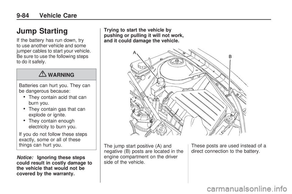
The jump start positive (A) and
negative (B) posts are located in the
engine compartment on the driver
side of the vehicle.
These posts are used instead of a
direct connection to the battery.
9-84 Vehicle Care
Page 337 of 372
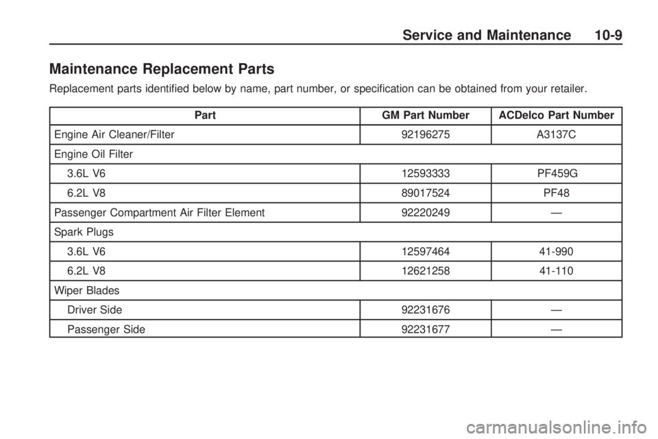
Maintenance Replacement Parts
Replacement parts identified below by name, part number, or specification can be obtained from your retailer.
PartGM Part Number ACDelco Part Number
Engine Air Cleaner/Filter 92196275A3137C
Engine Oil Filter 3.6L V6 12593333PF459G
6.2L V8 89017524PF48
Passenger Compartment Air Filter Element 92220249—
Spark Plugs 3.6L V6 1259746441-990
6.2L V8 1262125841-110
Wiper Blades Driver Side 92231676—
Passenger Side 92231677—
Service and Maintenance 10-9
Page 350 of 372
General Motors of Canada also
has a Mobility Program.
Call 1-800-GM-DRIVE (463-7483)
for details. TTY users call
1-800-263-3830.
Roadside Assistance
Program
For U.S. purchased vehicles,
call1-800-CHEV-USA
(1-800-243-8872); (Text telephone
(TTY): 1-888-889-2438).
For Canadian purchased vehicles,
call1-800-268-6800.
Service is available 24 hours a day,
365 days a year.
Calling for Assistance
When calling Roadside Assistance,
have the following information ready:
•Your name, home address, and
home telephone number
•Telephone number of your
location
•Location of the vehicle
•Model, year, color, and license
plate number of the vehicle
•Odometer reading, Vehicle
Identification Number (VIN), and
delivery date of the vehicle
•Description of the problem
Coverage
Services are provided up to 5 years/
100,000 miles (160 000 km),
whichever comes first.
In the U.S., anyone driving the
vehicle is covered. In Canada, a
person driving the vehicle without
permission from the owner is
not covered.
Roadside Assistance is not a part of
the New Vehicle Limited Warranty.
Chevrolet and General Motors
of Canada Limited reserve the right
to make any changes or discontinue
the Roadside Assistance program
at any time without notification.
Chevrolet and General Motors of
Canada Limited reserve the right to
limit services or payment to anowner or driver if they decide the
claims are made too often, or
the same type of claim is made
many times.
Services Provided
•
Emergency Fuel Delivery:
Delivery of enough fuel for
the vehicle to get to the nearest
service station.
•Lock-Out Service:Service is
provided to unlock the vehicle
if you are locked out. A remote
unlock may be available if
you have OnStar
®. For security
reasons, the driver must
present identification before this
service is given.
•Emergency Tow From a Public
Road or Highway:Tow to the
nearest Chevrolet dealer for
warranty service, or if the vehicle
was in a crash and cannot be
driven. Assistance is also
given when the vehicle is stuck
in the sand, mud, or snow.
12-6 Customer Information
Page 355 of 372
If a Crash Occurs
If there has been an injury, call
emergency services for help. Do not
leave the scene of a crash until
all matters have been taken care of.
Move the vehicle only if its position
puts you in danger, or you are
instructed to move it by a police
officer.
Give only the necessary information
to police and other parties involved
in the crash.
For emergency towing seeRoadside
Assistance Program on page 12-6.
Gather the following information:
•Driver’s name, address, phone
number
•Driver’s license number
•Owner’s name, address, phone
number
•Vehicle license plate
•Vehicle make, model and
model year
•Vehicle Identification
Number (VIN)
•Insurance company and policy
number
•General description of the
damage to the other vehicle
Choose a reputable repair facility
that uses quality replacement parts.
See “Collision Parts” earlier in
this section.
If the airbag has inflated, seeWhat
Will You See After an Airbag
Inates? on page 2-27.
Managing the Vehicle Damage
Repair Process
In the event that your vehicle
requires damage repairs, GM
recommends that you take an active
role in its repair. If you have a
pre-determined repair facility
of choice, take your vehicle there, or
have it towed there. Specify to the
facility that any required
replacement collision parts be
original equipment parts, either newGenuine GM parts or recycled
original GM parts. Remember,
recycled parts will not be covered
by your GM vehicle warranty.
Insurance pays the bill for the repair,
but you must live with the repair.
Depending on your policy limits,
your insurance company may
initially value the repair using
aftermarket parts. Discuss this with
your repair professional, and
insist on Genuine GM parts.
Remember if your vehicle is leased
you may be obligated to have
the vehicle repaired with Genuine
GM parts, even if your insurance
coverage does not pay the full cost.
If another party’s insurance
company is paying for the repairs,
you are not obligated to accept
a repair valuation based on
that insurance company’s collision
policy repair limits, as you have
no contractual limits with that
company. In such cases, you can
have control of the repair and
parts choices as long as cost stays
within reasonable limits.
Customer Information 12-11