CHEVROLET CITATION 1980 1.G Service Manual
Manufacturer: CHEVROLET, Model Year: 1980, Model line: CITATION, Model: CHEVROLET CITATION 1980 1.GPages: 95, PDF Size: 21.48 MB
Page 41 of 95
Downloaded from www.Manualslib.com manuals search engine Speakers:
NOTICE: All Oelco Sound Systems have ungrounded Sp8li!kers. Installing add-on tape players. CBs or other units that use the vehicle speakers may damage your Delco Sound System and impair operation of the added unit. Please consult your dealer in advance -i f you are conSidering additions.
FM Reception - Although FM is normally static free, reception can be limited by terrain, atmospheric conditions, station strength and distance from the
transmitter. Buildings or other obstructions can cause momentary static, nutter or station swapping. If you cannot keep good reception, tuning to a stronger
station
will bring improvement.
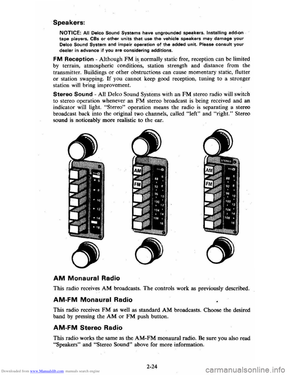
Stereo Sound - All Delco Sound Systems with an FM stereo radio will switch
to stereo operation whenever -an FM stereo broa dcast is being received and an
indicator will light. "Stereo" operation means the radio is separating a stereo
broadcast back into the original two channels, called "left" and "right." Stereo
sound is noticeably more realistic to the ear.
AM Monaural Radio
This radio receives AM broadcasts . The controls work as previously described.
AM-FM Monaural Radio
This radio receives FM as wen as standard AM broadcasts . Choose the desired
band
by pressing the AM or FM push button .
AM-FM Stereo Radio
This radio works the same as the AM-FM monaural radio. Be sure-you also read "Speakers" and "Stereo Sound" above_ for more information .
2-24
Page 42 of 95
Downloaded from www.Manualslib.com manuals search engine AM-FM Stereo with Citizens Band Transceiver
If your vehicle has an optional Delco GM Citizens Band radio, please refer to
the separdte booklet supplied with this unit.
MOBILE RADIO SYSTEMS
Mobile two-way units are subject to Federal Communications Commission (FCC) regulations' arid must be-installed by trained radio people . Mobile telephones
installed
by your local phone 'company, Citizens Band (CB) radios, and garage
door openers normally will not affect vehicle operation.
If any other mobile radio
transmitters are installed, there can
possibly , be _ adverse effects on vehicle
operation.
Antenna
The standard radioanterma is incorporated in the windshield glass. If necessary,
adjustments for maximum antenna effectiveness can be made by your Authorized
Dealer.
Power. Antenna
The optional power antenna is controlled by the radio. When the radio is ON the
antenna will go up. When the radio is turned OFF either by the ON/OFF knob
or by turning the ignition switch to the OFF poSition, the antenna will go down.
OTHER CONTRQLS AND
FEATURES
Hatchback Coupe
·R.ear Compartment lid -UnlOCk.' and open the lid with your oval hta,d key.
Close the lid firmly to lock.
folding Rear Seilt
The folding rear seat quickly folds to heir provide aq.ditional ,cargo space.
To operate , the folding rear seat:
• Pull the seat cushion forward and up toward the front seatback.
• Pull the seatback strap downward and forward to release the:: seatback latch.
• Swing seatback forward and down to form deck.
• When return.ing seat to the passenger position make sure seatback is latched.
Check now and then to see
if the latch on any folding rear seat works properly.
'To do this. push forward andreat',wai'd on the top of the seatback. If the seat does
not latch properly in the upright. posttion, have it repaired.
Keep
seat belt webbing and hardware clear of seat parts when you tilt folding seats
forward or rearward , This .. helps prevent damage to these bell systems.
CAUTION: The hatchback should be closed while driving to help avoid drawing dangerous exhausigaS8s into the car. (See "Engine Exhaust Gas Caution (Carbon Monoxide)" at the beginning of thi. section.)
2-25
Page 43 of 95
Downloaded from www.Manualslib.com manuals search engine Remote Control Rear Quarter Swing-Out Windows
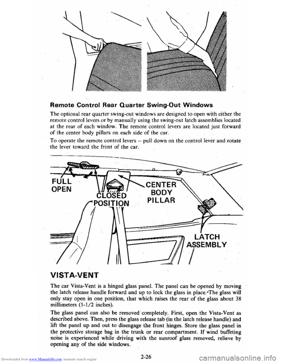
The optional rear quarter swing~oul windows are designed to open with either the
r e m 'ote control levers Of by manually using the swing-out latch assemblies located
at the rear of each window. The remote control levers are located just forward
o f the center
bod y pillars on each side of the car.
T o operate the remote control levers .-pull down on the cont ro l lever and rotate
the lever toward the front of the car.
OPEN
VISTA-VENT
CENTER
BODY
PILLAR
1========7.~ TCH r: ASSEMBLY
/
The car Vista-Vent is a hinged glass'panel. The panel can be opened by moving
the latch release handle forward and up
to lock the glass in place . ·The glass will
only. stay open in one position, that which raises the fear of the glass about 38 millimeters (1-112 inches).
The glass
panel' can also be removed completely . First, open the Vista-Vent as
described above.
Then, press the glass release tab (in the latch release handle) and
lift the panel up and out to disengage the front hinges . Store the glass panel in
the protective storage bag in the trunk or rear companment. If wind buffeting
noise is experienced while driving with the sunroof glass removed. relieve by opening any of the side· windows .
2-26
Page 44 of 95
Downloaded from www.Manualslib.com manuals search engine CAUTION: To help avoid personal injury and/or equipment damage-
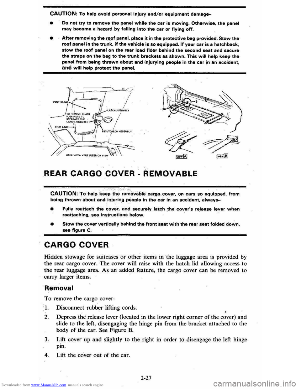
• Do not try to remove the panel while the car is moving. Otherwise. the panel may become a hazard by falling into the car or flying off.
• After removing the rQof panel, place it in the protective bag provided. Stow the roof panel in the trunk. if the vehicle is so equipped. If your car is a hatchback. stow the roof panel on the rear load floor behind the second seat and secure the straps on the bag to the trunk brackets as shown. This will help keep the panel from being thrown about andinjurying people in the car in an accident, and will help protect the panel.
I LAlCH ASIl~MElLV
®/ , MClI~HION MSl .. SLv
I
REAR CARGO COVER· REMOVABLE
CAUTION: To help keep the remova61e cargo cover, on cars so equipped, from being thrown about and injuring people in the car in an accident, always-
• Fully reattach the cover, and securely latch the cover's release lever when reattaching, see instructions below.
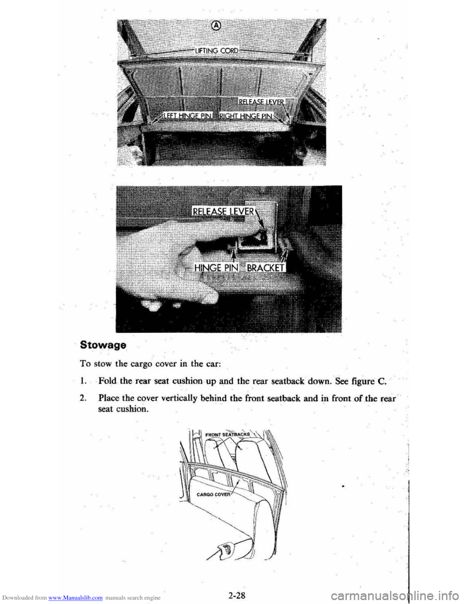
• Stow the cover vertically behind the front seat with the rear seat folded down. see figure C.
CARGO COVER
Hidden stowage for suitcases or other items in the luggage area is provided by
the rear cargo cover. The cover will raise with the hatch lid allowing access to
the rear luggage area. As an added feature. the cargo cover can be removed to
carry larger items.
Removal
To remove the cargo cover:
1. Disconnect rubber lifting cords.
2. Depress the release lever (located in the lower right corner of the cover) and
slide to the left, disengaging the hinge pin from the bracket attached to the
body
of the car. See Figure B.
3. Lift cover up and slightly to the right in order to disengage the left hinge
pin.
4. Lift the cover out of the car.
2-27
Page 45 of 95
Downloaded from www.Manualslib.com manuals search engine Stowage
To sto w the cargo cover in the car:
1. Fold . the rear seat cushion , up and the Tear seatba ck ' down. See figure C.
2 .
Plac e the cover vertically behind the front seatback and in &ootof the rear
seat cu shion.
2 -28
1 !
Page 46 of 95
Downloaded from www.Manualslib.com manuals search engine Insta"ation
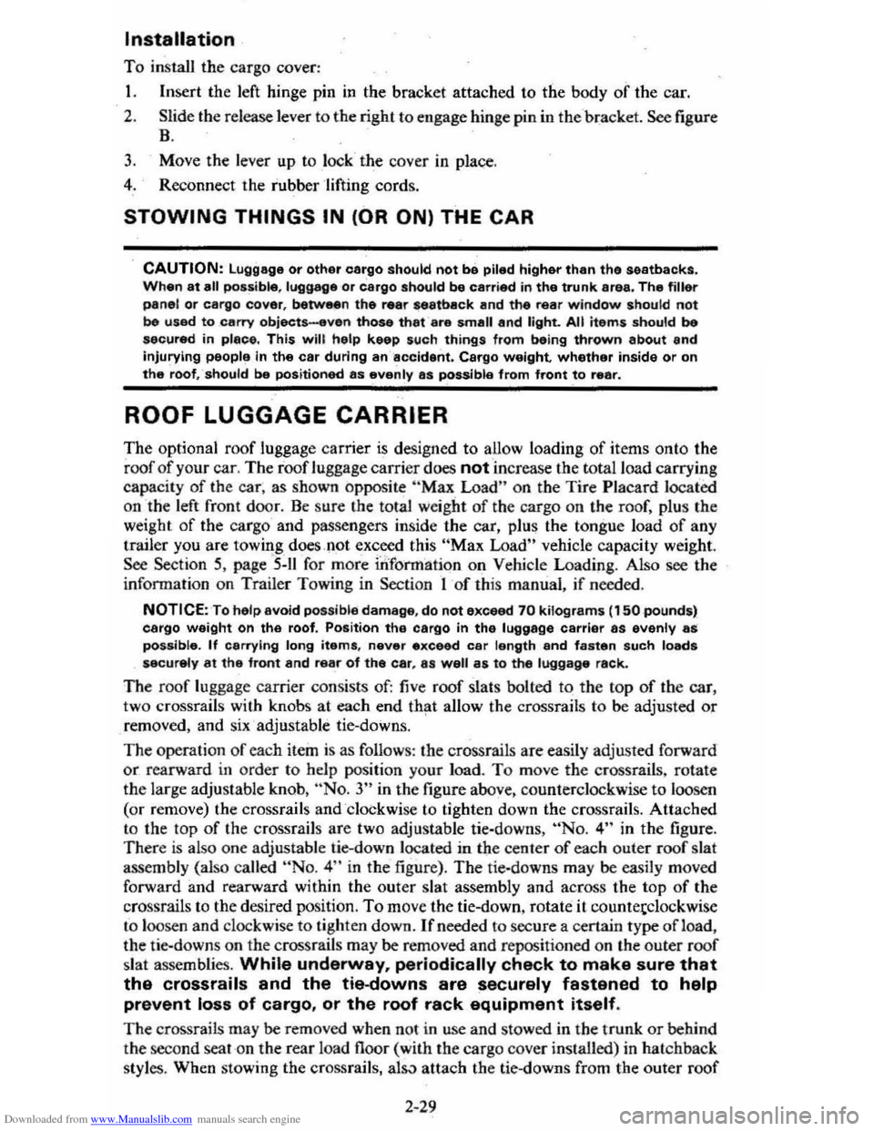
To install the cargo cover:
1. Insert the left hinge pin in the bracket attached to the body of the car.
2. Slide the release lever to the right to engage hinge pin in the 'bracket. See figure
B.
3. Move the lever up to lock the cover in place.
4. Reconnect the rubber 'lifting cords.
STOWING THINGS IN (OR ON) THE CAR
CAUTION: luggage or other cergo should not be piled higher than the seatbacks, When at all possible, luggage or cargo should be C8rrifHj in the trunk area. The filler panel or cargo cover, between the rear 88atback and the rear window should not be used to carry objects-even those that are small and light. All nems should be secured in place. This will help keep such things from being thrown about and Injurying people in the car during an accident. Cargo weight whether inside or on the roof, should be positioned as evenly as possible from front to rear.
ROOF LUGGAGE CARRIER
The optional roof luggage carrier is designed to allow loading of items onto the
roof
of your car. The roof luggage carrier does not increase the total load carrying
capacity of th e car , as shown opposite "Max Load" on the Tire Placard located
on the left front door. Be sure the total weight of the cargo on the roof, plus the
weight
of the cargo and passe ngers inside the car, plus the tongue load of any
trailer you are towing does
,1;10t exc_eed this "Max Load" vehicle capacity weight. See Section 5, page "5-11 for more information on Vehicle Loading . Also see the
infonnation on Trailer Towing
in Section 1 of this manual . if needed .
NOTICE:To helpayoid pOSSible damage, do not exceed 70 kilograms (1 50 pounds), cargo weight on the roof. Position the cargo in the luggage carrier as evenly as: pOssible. If carrying long items, never exceed car length and fasten such loads securely at the front and rear of the car, as well as to the luggage rack.
The roof luggage carrier consists of: five roof slats bolted to the top of the car,
two crossrails with knobs at each end th~t allow the crossrails to be adjusted or removed, and six' adjustable tie-downs.
The operation
of each item is as follows: the crossrails are easily adjusted forward
or rearward in order to help position your load. To move the crossrails , rotate
the large adjustable knob, ··No. 3" in the figure above. counterclockwise to loosen
(or remove) the crossrails and 'clockwise to tighten down the cros srails. Attached
to the top
of the crossrails are two adjustable tie-downs, "No.4" in the figure.
Ther e is also one adjustable lie-down located in the center of each outer roof slat
assembly (also called
"No.4" in the figure) . The tie-downs may be easily moved
forward and rearward within the outer slat assembly and across the top
of the
crossrails to the desired position.
To move the tie-down . rotate it countetclockwise
to loosen and clockwise to tighten down. If needed to sec ure a certain type of lead,
the tie-downs on the
crossratls may be removed and repos itioned on the outer roof
slat assemblies. While underway, periodically check to make sure that
the crossrails and the tie-downs are securely fastened to help
prevent loss of cargo, or the roof rack equipment itself.
The crossrails may be removed when not in use and stowed in the trunk or behind
the second seat on the rear load floor (with the carg o cover installed) in hatchback
style
s. When stowing the cressrails, al5..1 attach the tie-downs from the outer roof
2-29
Page 47 of 95
![CHEVROLET CITATION 1980 1.G Service Manual Downloaded from www.Manualslib.com manuals search engine [I] ROOF RAIL ASM.
[1] CROSSRAILS
rnCROSSRAIL KNOBS
[!]TIE-DOWNS
slat assemblies to the ex ir a retairier provided on the to p of ea CHEVROLET CITATION 1980 1.G Service Manual Downloaded from www.Manualslib.com manuals search engine [I] ROOF RAIL ASM.
[1] CROSSRAILS
rnCROSSRAIL KNOBS
[!]TIE-DOWNS
slat assemblies to the ex ir a retairier provided on the to p of ea](/img/24/8083/w960_8083-46.png)
Downloaded from www.Manualslib.com manuals search engine [I] ROOF RAIL ASM.
[1] CROSSRAILS
rnCROSSRAIL KNOBS
[!]TIE-DOWNS
slat assemblies to the ex ir a retairier provided on the to p of eac h crossraiL
See you r Ch evrolet dealer for attachme nts to your Chev rolet luggage ca rrier to
h old bicycles, sk
is _and other it em s. and for straps to h eJp secure your cargo, whic h
a re avail"ab le a s accesso ries.
2-30
Page 48 of 95
Downloaded from www.Manualslib.com manuals search engine /
SECTION 3
IN CASE OF EMERGENCY
See also ",Engine Exhaust Gas Caution (Carbon Monoxide),' at the beginning of
"Starting and Operating," Section 2 of this manual.
FOUR·WAY HAZARD WARNING FLASHER
•. Use the warning flasher to warn other drivers any lime your vehicle -becomes
a traffic hazard, day or nighc.
• Avoid 'stopping on the roadway ,if possible.
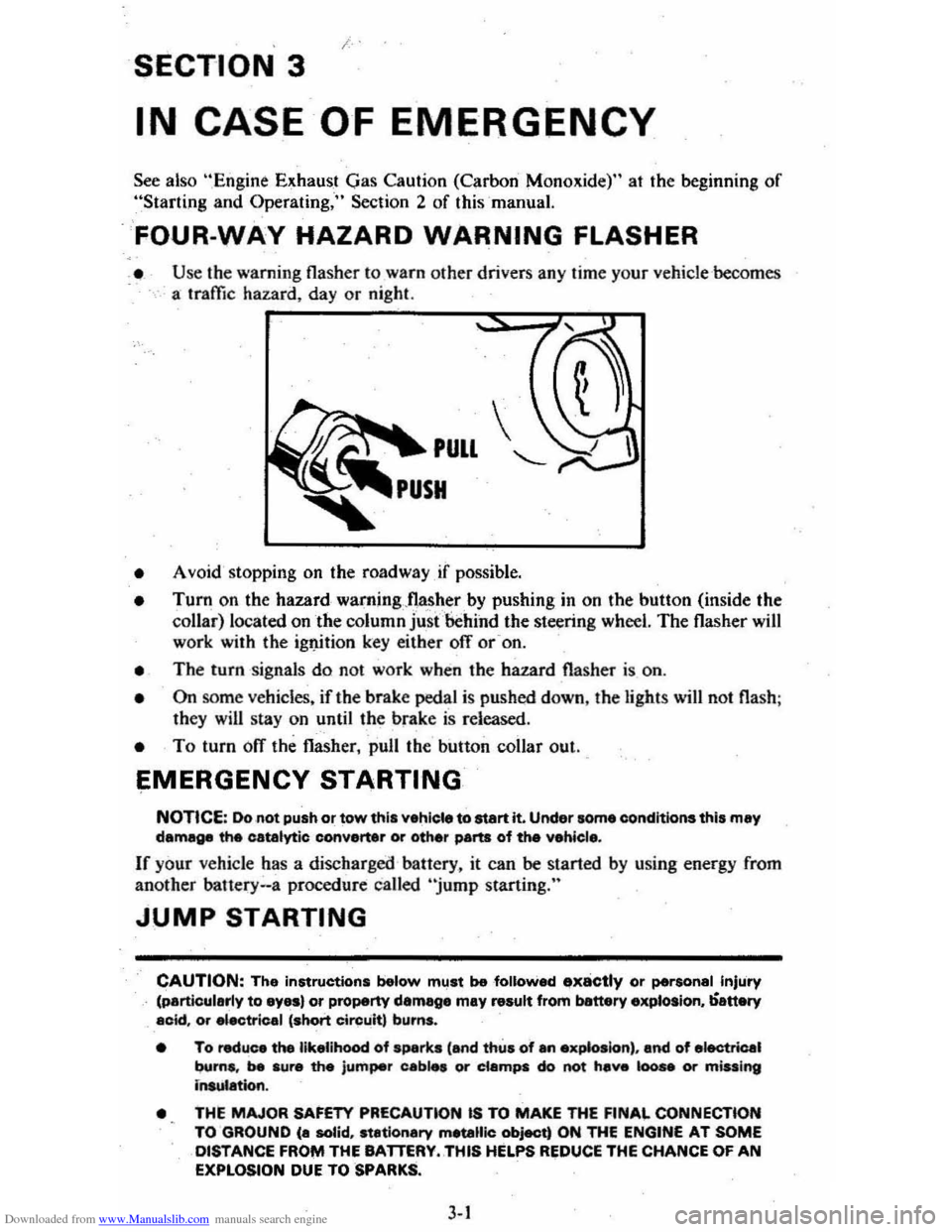
• Turn on the hazard waming"nas~,er by pushing in on the button (inside the collar) located on the column just 'behind the steering wheel. The flasher will work with the ig1J.ition key either ofT or -on.
• The turn signals do not work when the hazard flasher is on.
• On some vehicles. if the brake pedal is pushed down, the light s will not flash ;
they will stay on until the brake is released .
• To turn ofT the flasher, pull the button collar out ..
EMERGENCY STARTING
NOTICE: Do not push or tow this vehiele to start it. Under some eonditions this may damage the catalytic converter or other parts of the vehicl ••
If your vehicle has a discharged battery. it can be started by using energy from
another bauery .. a procedure called "jump starting."
JUMP STARTING
CAUTION: The instructions below mllst be followed ..,x8ctly or personal Injury (particularly to eyas) or property damege may result from banery explosion, ';-attery acid. or "ectrical 'short Circuit, burns.
• To reduce the likelihood of sparks 'and thus of an exp&oslon) , and of electrical
burns. be sure the jumper cab," or ciampa do not hev. 100 .. Of m;uing insulation.
•
THE MAJOR SAFETY PRECAUTlON IS TO MAKE THE FINAL CONNECTION
TO GROUND (a solid, stationary metallic object) ON THE ENGINE AT SOME DISTANCE FROI'II THE BATTERY .. THIS HELPS REDUCE THE CHANCE OF AN EXPLOSION DUE TO SPARKS.
3-1
Page 49 of 95
Downloaded from www.Manualslib.com manuals search engine • To lessen the chance of an explosion, never expose a battery to open flames
or electric sparks. Also do not smoke near a ,battery. Batteries give off a gas which is flammable and explosive.
• To lessen the risk of injury incase an explosion does occur, wear eye protection or shield your eyes when working near any battery. Do not lean over a battery.
• Do not allow battery fluid to contact eyes, skin, fabrics, or painted surfaces
because battery fluid is a corrOsiVe acid. Flush any contacted area with water immediately a,nd thoroughly. Also get medical help if eyes are affected.
• To lessen the riskofa short circuit. remove rings, metal watch bands and otl:ler metal jewelry. Also do not allow metal tools to contact at the same time the positive battery terminal (or any metal connected to this terminal) and any other metal em either "ehicle. Make certain when attaching the jumper cable clamps rothe positive terminals of the batteries that neither clamp contacts any other metal.
• This
vehicle has a 12 volt battery and a negative ground electrical system. Make sure that the other vehicle als~ has a 12 volt battery and that the negative terminal, is .'grounc::ted(attached to a metal, part of the vehicle). Its owner's manual may give you that information, If unsure of the other vehicle's voltage (or if the voltage and/or ground on the other vehicle are different from your vehicle). do not try to jump startas personal injury or severe damage to electrical and electronic parts may result.
• If the discharged battery has filler caps. check the fluid level. ( 00 not check with an Op~tn flame and db not smoke .) Add clear drinking water to the proper level if low, and replace the caps before jump starting.
I. Position, the vehicle with'the good (charged)ba,.ttery so that the jump starting
cables will reach.
Do not let the vehicles t"ouch.
2. Turn off all electric motors and accessories in both vehicles. Turn off all lights
except those needed to protect the vehicles or light up the work area. Turn
off the ignition, apply the parking brake firmly, and shift the automatic transaxleto "p"o.?ark) (manual transaxle to "N"(Neutral) in both vE-hicles.
3. Jumper Cable Connection Instructions (See illustration) .
• Connect the first jumper cable from the positive" +" (red) terininal on
one battery to the positive "+" (red) terminal on the other battery.
Never, connect "+" (red) to "~" (black), or '\" to "+".
• Next, connect one end of the second cable to the grounded negative "."
(black) tenninal of the good (charged) battery.
• Lastly, connect the othetend of the second jumper cable to a solid,
stationary, metallic point on the engine of the vehicle with the discharged
battery but at a
point away from the battery --450 millimeters (18 '1
inches) or more from the battery if possible. Do not connect it to or attach it near pulleys, fans, or other parts that will move wHen the engine
is started. Don't touctt hot manifolds as they _can cause severe burns. If hot or moving parts can be avoided, the MOUNTING BRACKETS for
the Delcotron generator,
or the air conditioner compressor, ,generally
make a good point for-this final ground attachment. Take care that the
jtimper cable does
hot contact moving parts on or near the generator
or compressor.)
4. Start the engine of the vehicle with the good (charged) battery and run the
engine at a moderate speed.
3-2
Page 50 of 95
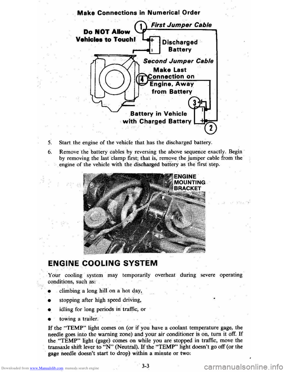
Downloaded from www.Manualslib.com manuals search engine Make Connections In Numerical Order
First Jumper Cable
Discharged
Battery
Make Last
onnectlon on
Engine. Away
from Battery
Battery in Vehicle
with Charged Battery LC"""=-
5. Start the engine of the vehicle that has the discharged battery.
6. Remove the battery cables by reversing the above sequence exactly. Begin
by removing the last clamp first; that is, remove the jumper cable· from the engine of the vehicle with the' discha:r,g:edbatTery as the' first step.
ENGINE COOLING SYSTEM
Your cooling system may temporarily overheat during severe operating
conditions, such as:
• climbing a long hilLon a hot qay,
•
stopping after high speed driving,
• idling for long periods' in' traffic, or
• towing a trailer.
If theUTEMP" light comes on (or if you have a coolant temperature gage, the
needle goes
into the warning zone) and your air conditioner is on, tum it off. If
the. 'ITEMP" light (gage) comes on while you are stopped in traffic, move the
transaxle shift lever to UN" (Neutral). If the "TBMP" light doesn't go off (or the
gage
needle doesn't start to drop) within a minute or two:
3-3