display CHEVROLET DYNASTY 1993 Owner's Guide
[x] Cancel search | Manufacturer: CHEVROLET, Model Year: 1993, Model line: DYNASTY, Model: CHEVROLET DYNASTY 1993Pages: 2438, PDF Size: 74.98 MB
Page 471 of 2438
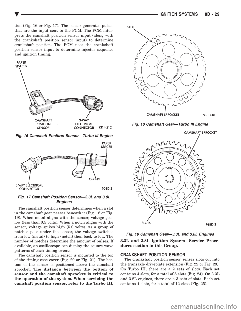
tion (Fig. 16 or Fig. 17). The sensor generates pulses
that are the input sent to the PCM. The PCM inter-
prets the camshaft position sensor input (along with
the crankshaft position sensor input) to determine
crankshaft position. The PCM uses the crankshaft
position sensor input to determine injector sequence
and ignition timing.
The camshaft position sensor determines when a slot
in the camshaft gear passes beneath it (Fig. 18 or Fig.
19). When metal aligns with the sensor, voltage goes
low (less than 0.5 volts). When a notch aligns with the
sensor, voltage spikes high (5.0 volts). As a group of
notches pass under the sensor, the voltage switches
from low (metal) to high (notch) then back to low. The
number of notches determine the amount of pulses. If
available, an oscilloscope can display the square wave
patterns of each timing events. The camshaft position sensor is mounted to the top
of the timing case cover (Fig. 20 or Fig. 21). The bot-
tom of the sensor is positioned above the camshaft
sprocket. The distance between the bottom of
sensor and the camshaft sprocket is critical to
the operation of the system. When servicing the
camshaft position sensor, refer to the Turbo III, 3.3L and 3.8L Ignition SystemÐService Proce-
dures section in this Group.
CRANKSHAFT POSITION SENSOR
The crankshaft position sensor senses slots cut into
the transaxle driveplate extension (Fig. 22 or Fig. 23).
On Turbo III, there ar e a 2 sets of slots. Each set
contains 4 slots, for a total of 8 slots (Fig. 24). On 3.3L
and 3.8L engines, there ar e a 3 sets of slots. Each set
contains 4 slots, for a total of 12 slots (Fig. 25).
Fig. 16 Camshaft Position SensorÐTurbo III Engine
Fig. 17 Camshaft Position SensorÐ3.3L and 3.8L Engines
Fig. 18 Camshaft GearÐTurbo III Engine
Fig. 19 Camshaft GearÐ3.3L and 3.8L Engines
Ä IGNITION SYSTEMS 8D - 29
Page 493 of 2438
INSTRUMENT PANEL AND GAUGES
CONTENTS
page page
AA BODY .............................. 1
AC AND AY BODIES .................... 23 AG AND AJ BODIES
.................... 42
AP BODY ............................. 58
AA BODY INDEX
page page
Cluster and Gauge Service and Testing ........ 2
Electronic Cluster ........................ 13
Fuel GaugeÐFlexible Fuel .................. 2
Gauges ................................. 7
General Information ........................ 1 Instrument Panel
......................... 21
Interior Lamp Replacement ................. 21
Mechanical/Electronic Cluster Removal ......... 5
Switch and Panel Component Service ......... 15
GENERAL INFORMATION
INSTRUMENT CLUSTERS
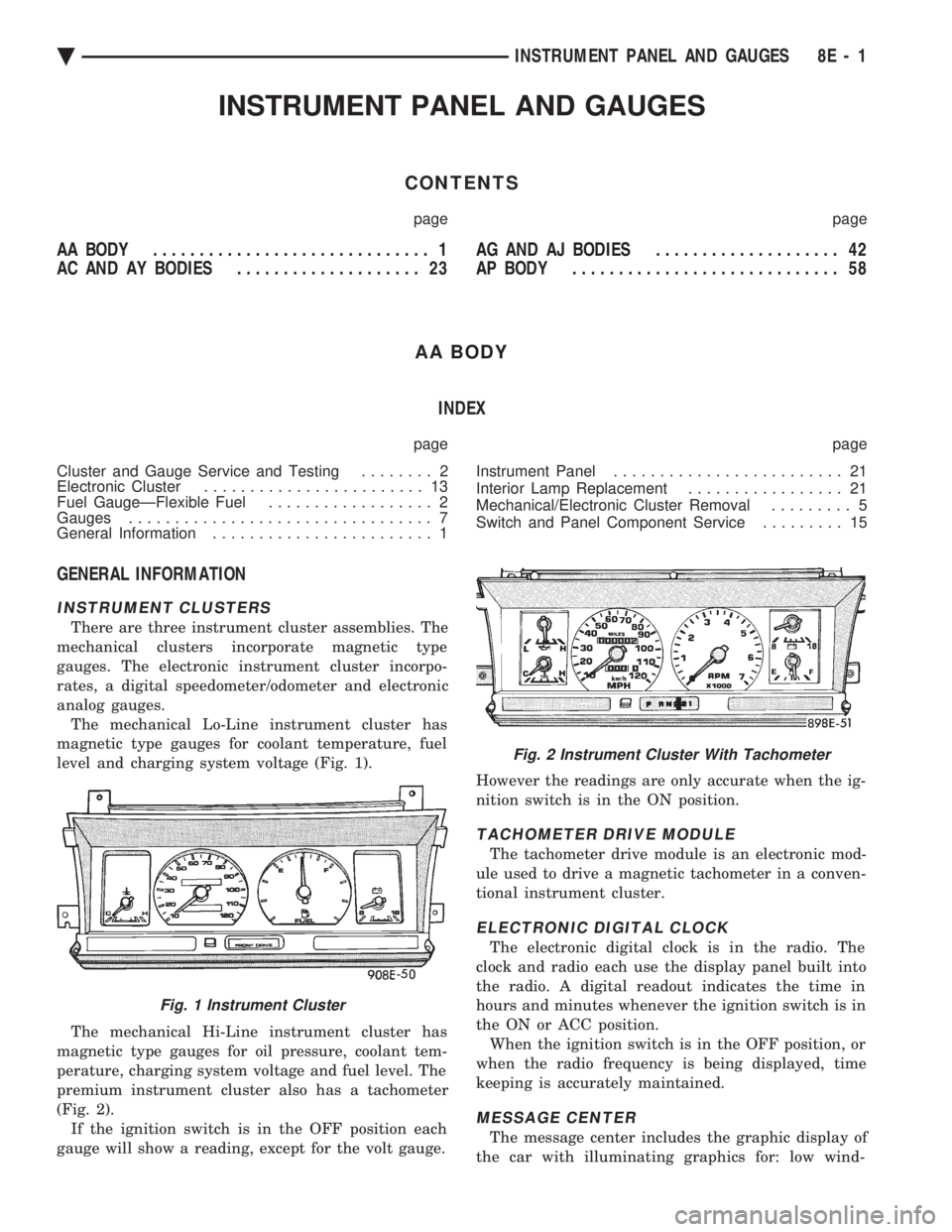
There are three instrument cluster assemblies. The
mechanical clusters incorporate magnetic type
gauges. The electronic instrument cluster incorpo-
rates, a digital speedometer/odometer and electronic
analog gauges. The mechanical Lo-Line instrument cluster has
magnetic type gauges for coolant temperature, fuel
level and charging system voltage (Fig. 1).
The mechanical Hi-Line instrument cluster has
magnetic type gauges for oil pressure, coolant tem-
perature, charging system voltage and fuel level. The
premium instrument cluster also has a tachometer
(Fig. 2). If the ignition switch is in the OFF position each
gauge will show a reading, except for the volt gauge. However the readings are only accurate when the ig-
nition switch is in the ON position.
TACHOMETER DRIVE MODULE
The tachometer drive module is an electronic mod-
ule used to drive a magnetic tachometer in a conven-
tional instrument cluster.
ELECTRONIC DIGITAL CLOCK
The electronic digital clock is in the radio. The
clock and radio each use the display panel built into
the radio. A digital readout indicates the time in
hours and minutes whenever the ignition switch is in
the ON or ACC position. When the ignition switch is in the OFF position, or
when the radio frequency is being displayed, time
keeping is accurately maintained.
MESSAGE CENTER
The message center includes the graphic display of
the car with illuminating graphics for: low wind-
Fig. 1 Instrument Cluster
Fig. 2 Instrument Cluster With Tachometer
Ä INSTRUMENT PANEL AND GAUGES 8E - 1
Page 494 of 2438
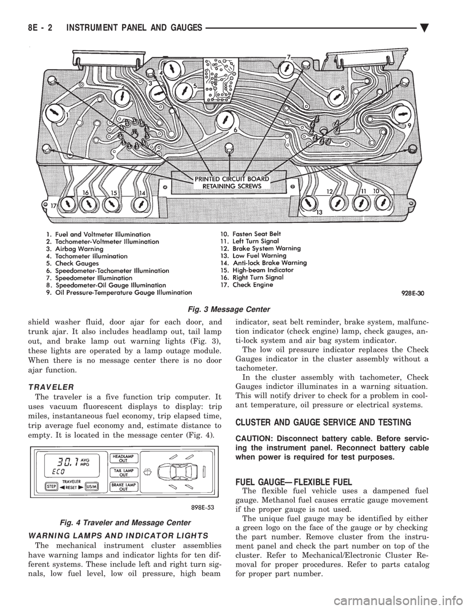
shield washer fluid, door ajar for each door, and
trunk ajar. It also includes headlamp out, tail lamp
out, and brake lamp out warning lights (Fig. 3),
these lights are operated by a lamp outage module.
When there is no message center there is no door
ajar function.
TRAVELER
The traveler is a five function trip computer. It
uses vacuum fluorescent displays to display: trip
miles, instantaneous fuel economy, trip elapsed time,
trip average fuel economy and, estimate distance to
empty. It is located in the message center (Fig. 4).
WARNING LAMPS AND INDICATOR LIGHTS
The mechanical instrument cluster assemblies
have warning lamps and indicator lights for ten dif-
ferent systems. These include left and right turn sig-
nals, low fuel level, low oil pressure, high beam indicator, seat belt reminder, brake system, malfunc-
tion indicator (check engine) lamp, check gauges, an-
ti-lock system and air bag system indicator. The low oil pressure indicator replaces the Check
Gauges indicator in the cluster assembly without a
tachometer. In the cluster assembly with tachometer, Check
Gauges indictor illuminates in a warning situation.
This will notify driver to check for a problem in cool-
ant temperature, oil pressure or electrical systems.
CLUSTER AND GAUGE SERVICE AND TESTING
CAUTION: Disconnect battery cable. Before servic-
ing the instrument panel. Reconnect battery cable
when power is required for test purposes.
FUEL GAUGEÐFLEXIBLE FUEL
The flexible fuel vehicle uses a dampened fuel
gauge. Methanol fuel causes erratic gauge movement
if the proper gauge is not used. The unique fuel gauge may be identified by either
a green logo on the face of the gauge or by checking
the part number. Remove cluster from the instru-
ment panel and check the part number on top of the
cluster. Refer to Mechanical/Electronic Cluster Re-
moval for proper procedures. Refer to parts catalog
for proper part number.
Fig. 3 Message Center
Fig. 4 Traveler and Message Center
8E - 2 INSTRUMENT PANEL AND GAUGES Ä
Page 505 of 2438
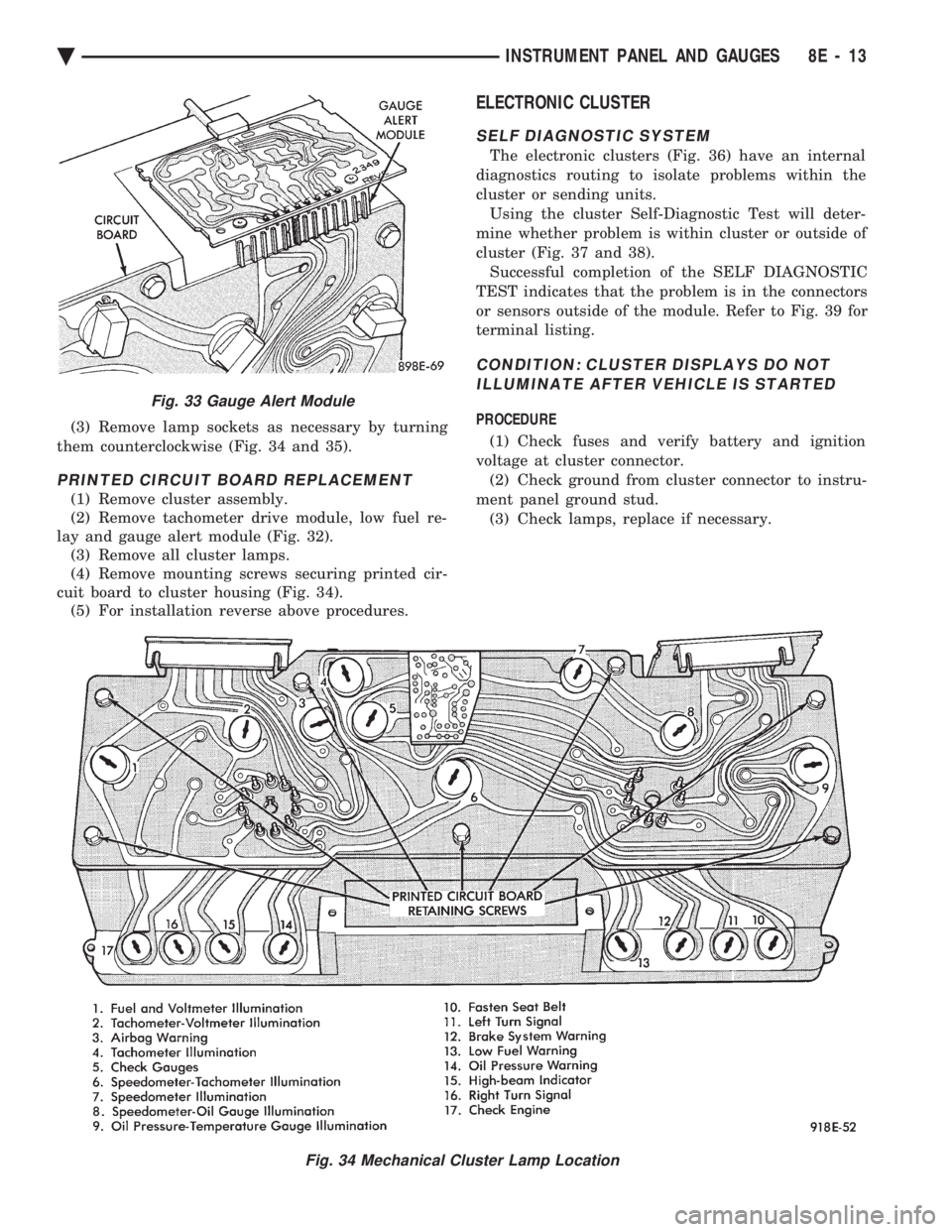
(3) Remove lamp sockets as necessary by turning
them counterclockwise (Fig. 34 and 35).
PRINTED CIRCUIT BOARD REPLACEMENT
(1) Remove cluster assembly.
(2) Remove tachometer drive module, low fuel re-
lay and gauge alert module (Fig. 32). (3) Remove all cluster lamps.
(4) Remove mounting screws securing printed cir-
cuit board to cluster housing (Fig. 34). (5) For installation reverse above procedures.
ELECTRONIC CLUSTER
SELF DIAGNOSTIC SYSTEM
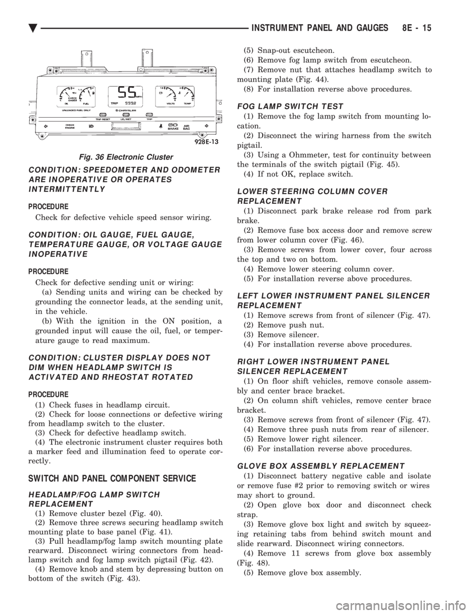
The electronic clusters (Fig. 36) have an internal
diagnostics routing to isolate problems within the
cluster or sending units. Using the cluster Self-Diagnostic Test will deter-
mine whether problem is within cluster or outside of
cluster (Fig. 37 and 38). Successful completion of the SELF DIAGNOSTIC
TEST indicates that the problem is in the connectors
or sensors outside of the module. Refer to Fig. 39 for
terminal listing.
CONDITION: CLUSTER DISPLAYS DO NOT ILLUMINATE AFTER VEHICLE IS STARTED
PROCEDURE
(1) Check fuses and verify battery and ignition
voltage at cluster connector. (2) Check ground from cluster connector to instru-
ment panel ground stud. (3) Check lamps, replace if necessary.
Fig. 34 Mechanical Cluster Lamp Location
Fig. 33 Gauge Alert Module
Ä INSTRUMENT PANEL AND GAUGES 8E - 13
Page 507 of 2438
CONDITION: SPEEDOMETER AND ODOMETER ARE INOPERATIVE OR OPERATESINTERMITTENTLY
PROCEDURE
Check for defective vehicle speed sensor wiring.
CONDITION: OIL GAUGE, FUEL GAUGE, TEMPERATURE GAUGE, OR VOLTAGE GAUGEINOPERATIVE
PROCEDURE
Check for defective sending unit or wiring: (a) Sending units and wiring can be checked by
grounding the connector leads, at the sending unit,
in the vehicle. (b) With the ignition in the ON position, a
grounded input will cause the oil, fuel, or temper-
ature gauge to read maximum.
CONDITION: CLUSTER DISPLAY DOES NOT DIM WHEN HEADLAMP SWITCH ISACTIVATED AND RHEOSTAT ROTATED
PROCEDURE
(1) Check fuses in headlamp circuit.
(2) Check for loose connections or defective wiring
from headlamp switch to the cluster. (3) Check for defective headlamp switch.
(4) The electronic instrument cluster requires both
a marker feed and illumination feed to operate cor-
rectly.
SWITCH AND PANEL COMPONENT SERVICE
HEADLAMP/FOG LAMP SWITCH REPLACEMENT
(1) Remove cluster bezel (Fig. 40).
(2) Remove three screws securing headlamp switch
mounting plate to base panel (Fig. 41). (3) Pull headlamp/fog lamp switch mounting plate
rearward. Disconnect wiring connectors from head-
lamp switch and fog lamp switch pigtail (Fig. 42). (4) Remove knob and stem by depressing button on
bottom of the switch (Fig. 43). (5) Snap-out escutcheon.
(6) Remove fog lamp switch from escutcheon.
(7) Remove nut that attaches headlamp switch to
mounting plate (Fig. 44). (8) For installation reverse above procedures.
FOG LAMP SWITCH TEST
(1) Remove the fog lamp switch from mounting lo-
cation. (2) Disconnect the wiring harness from the switch
pigtail. (3) Using a Ohmmeter, test for continuity between
the terminals of the switch pigtail (Fig. 45). (4) If not OK, replace switch.
LOWER STEERING COLUMN COVERREPLACEMENT
(1) Disconnect park brake release rod from park
brake. (2) Remove fuse box access door and remove screw
from lower column cover (Fig. 46). (3) Remove screws from lower cover, four across
the top and two on bottom. (4) Remove lower steering column cover.
(5) For installation reverse above procedures.
LEFT LOWER INSTRUMENT PANEL SILENCER REPLACEMENT
(1) Remove screws from front of silencer (Fig. 47).
(2) Remove push nut.
(3) Remove silencer.
(4) For installation reverse above procedures.
RIGHT LOWER INSTRUMENT PANEL SILENCER REPLACEMENT
(1) On floor shift vehicles, remove console assem-
bly and center brace bracket. (2) On column shift vehicles, remove center brace
bracket. (3) Remove screws from front of silencer (Fig. 47).
(4) Remove three push nuts from rear of silencer.
(5) Remove lower right silencer.
(6) For installation reverse above procedures.
GLOVE BOX ASSEMBLY REPLACEMENT
(1) Disconnect battery negative cable and isolate
or remove fuse #2 prior to removing switch or wires
may short to ground. (2) Open glove box door and disconnect check
strap. (3) Remove glove box light and switch by squeez-
ing retaining tabs from behind switch mount and
slide rearward. Disconnect wiring connectors. (4) Remove 11 screws from glove box assembly
(Fig. 48). (5) Remove glove box assembly.
Fig. 36 Electronic Cluster
Ä INSTRUMENT PANEL AND GAUGES 8E - 15
Page 515 of 2438
AC AND AY BODIES INDEX
page page
Electronic Cluster ........................ 34
Gauges ................................ 28
General Information ....................... 23
Interior Lamp Replacement ................. 41 Mechanical Cluster and Gauge Service
........ 24
Mechanical/Electronic Cluster Removal ........ 25
Switch and Panel Component Service ......... 37
GENERAL INFORMATION
MECHANICAL CLUSTER
The mechanical cluster includes a fuel, oil pres-
sure, coolant temperature, and voltmeter gauges. All
incorporate magnetic type gauges. When the ignition
switch is in the OFF position, the gauges will show a
reading; however, the readings are only accurate
when the ignition switch is in the ON position. The mechanical cluster also includes an electric
speedometer, driven by pulses from the vehicle speed
sensor (Fig. 1).
ELECTRONIC CLUSTER
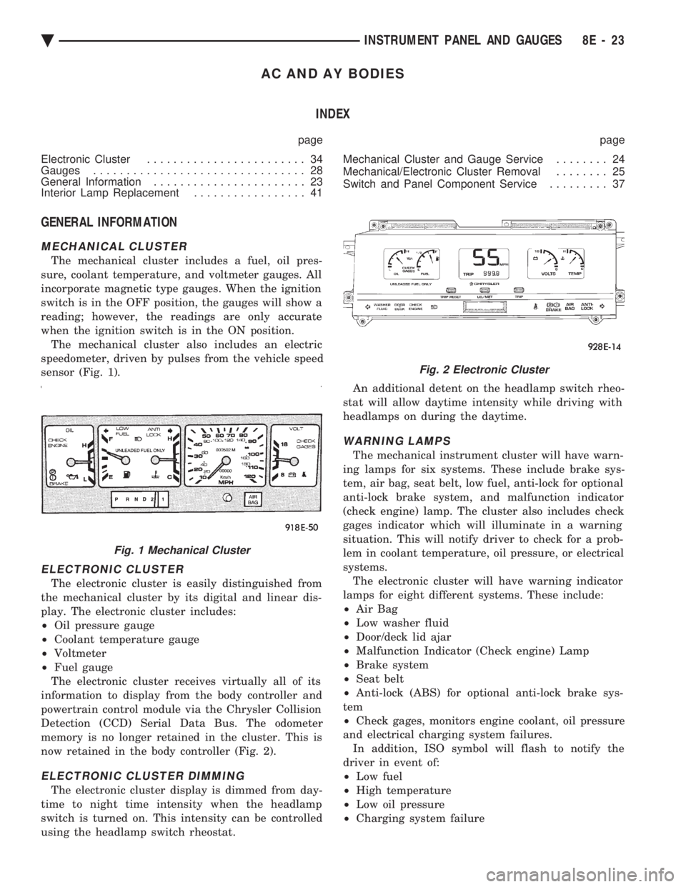
The electronic cluster is easily distinguished from
the mechanical cluster by its digital and linear dis-
play. The electronic cluster includes:
² Oil pressure gauge
² Coolant temperature gauge
² Voltmeter
² Fuel gauge
The electronic cluster receives virtually all of its
information to display from the body controller and
powertrain control module via the Chrysler Collision
Detection (CCD) Serial Data Bus. The odometer
memory is no longer retained in the cluster. This is
now retained in the body controller (Fig. 2).
ELECTRONIC CLUSTER DIMMING
The electronic cluster display is dimmed from day-
time to night time intensity when the headlamp
switch is turned on. This intensity can be controlled
using the headlamp switch rheostat. An additional detent on the headlamp switch rheo-
stat will allow daytime intensity while driving with
headlamps on during the daytime.
WARNING LAMPS
The mechanical instrument cluster will have warn-
ing lamps for six systems. These include brake sys-
tem, air bag, seat belt, low fuel, anti-lock for optional
anti-lock brake system, and malfunction indicator
(check engine) lamp. The cluster also includes check
gages indicator which will illuminate in a warning
situation. This will notify driver to check for a prob-
lem in coolant temperature, oil pressure, or electrical
systems. The electronic cluster will have warning indicator
lamps for eight different systems. These include:
² Air Bag
² Low washer fluid
² Door/deck lid ajar
² Malfunction Indicator (Check engine) Lamp
² Brake system
² Seat belt
² Anti-lock (ABS) for optional anti-lock brake sys-
tem
² Check gages, monitors engine coolant, oil pressure
and electrical charging system failures. In addition, ISO symbol will flash to notify the
driver in event of:
² Low fuel
² High temperature
² Low oil pressure
² Charging system failure
Fig. 1 Mechanical Cluster
Fig. 2 Electronic Cluster
Ä INSTRUMENT PANEL AND GAUGES 8E - 23
Page 516 of 2438
MESSAGE CENTER
The message center is a car graphic warning lamp
module. This conventional warning system and lo-
cated above the headlamp switch.
ELECTRONIC DIGITAL CLOCK
The electronic digital clock is in the radio. The
clock and radio each use the display panel built into
the radio. A digital readout indicates the time in
hours and minutes whenever the ignition switch is in
the ON or ACC position. When the ignition switch is in the OFF position, or
when the radio frequency is being displayed, time
keeping is accurately maintained. The procedure for setting the clock varies slightly
with each radio. The correct procedure is described
under the individual radio operating instructions re-
ferred to in the Owner's Manual supplied with the
vehicle.
AIR BAG WARNING SYSTEM
For testing of this system refer to Group 8M, Re-
straint Systems.
MECHANICAL CLUSTER AND GAUGE SERVICE
CAUTION: Disconnect negative battery cable, in en-
gine compartment, before servicing instrument
panel. When power is required for test purposes,
reconnect battery cable for the test only.
Disconnect negative battery cable after test and be-
fore continuing service procedures.
SENDING UNIT TEST
When a problem occurs with a cluster gauge, be-
fore disassembling the cluster to check the gauge,
check for a defective sending unit or wiring. (1) Sending units and wiring can be checked by
grounding the connector leads, at the sending unit,
in the vehicle. (2) With the ignition in the ON position; a
grounded input will cause the oil, fuel or tempera-
ture gauge to read at or above maximum.
CHECK GAUGES WARNING LAMP TESTS
The check gauges warning lamp is illuminated by
the low oil pressure sending unit switch or the body
controller when there is high temperature or charg-
ing system failure. To test the lamp, turn ignition key to the ON po-
sition without starting the vehicle. The low oil pres-
sure switch is grounded and the light will be on
indefinitely. If the lamp fails to light, pull the cluster and check
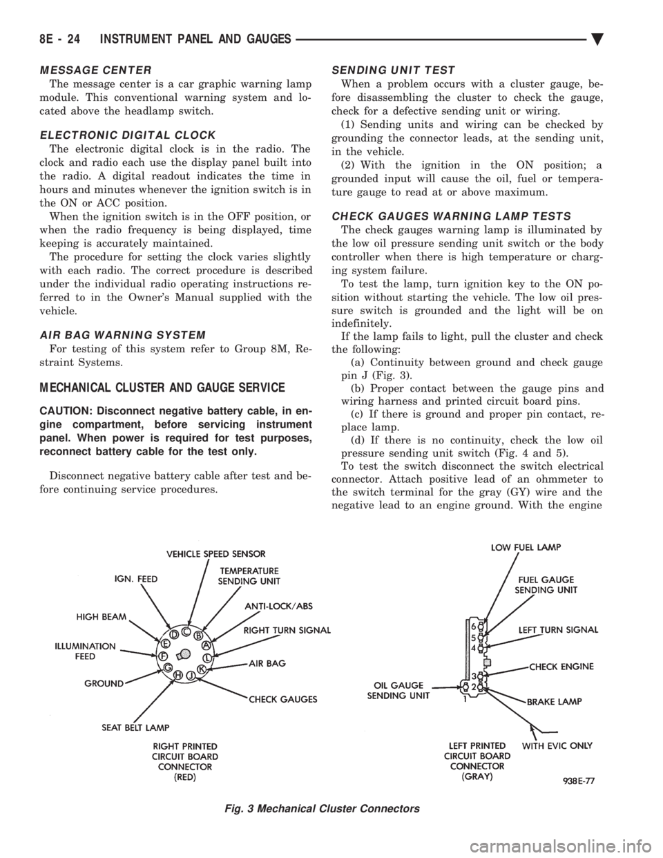
the following: (a) Continuity between ground and check gauge
pin J (Fig. 3). (b) Proper contact between the gauge pins and
wiring harness and printed circuit board pins. (c) If there is ground and proper pin contact, re-
place lamp. (d) If there is no continuity, check the low oil
pressure sending unit switch (Fig. 4 and 5).
To test the switch disconnect the switch electrical
connector. Attach positive lead of an ohmmeter to
the switch terminal for the gray (GY) wire and the
negative lead to an engine ground. With the engine
Fig. 3 Mechanical Cluster Connectors
8E - 24 INSTRUMENT PANEL AND GAUGES Ä
Page 526 of 2438
ELECTRONIC CLUSTER
SELF DIAGNOSTIC SYSTEM
The electronic clusters have an internal diagnostics
routing to isolate problems within the cluster or CCD
Bus. Using the cluster Self-Diagnostic Test will deter-
mine whether the problem is within the cluster or
outside of cluster (Fig. 29 and 30). Successful completion of the Self Diagnostic Test
indicates that the problem is in the CCD Bus, inter-
facing modules, connectors, or sensors outside of the
cluster. Refer to Fig. 31 for terminal listing.
CONDITION: CLUSTER DISPLAYS DO NOT ILLUMINATE AFTER VEHICLE IS STARTED
PROCEDURE
(1) Check fuses and verify battery and ignition
voltage at cluster connector. (2) Check ground from cluster connector to instru-
ment panel ground stud.
CONDITION: CLUSTER ASTERISK (*) FLASHES, CLUSTER DISPLAYS NOTINDICATING CORRECT DATA.
PROCEDURE
CCD bus problem. Use the Body Chassis Diagnos-
tic Manual to diagnose CCD Bus.
CONDITION: SPEEDOMETER AND ODOMETER ARE INOPERATIVE OR OPERATESINTERMITTENTLY
PROCEDURE
(1) If speedometer reads 0, or odometer is blank,
and cluster asterisk is flashing, use the Body Chassis
Diagnostic Manual to diagnose CCD Bus problem. (2) If cluster asterisk is not flashing, check for de-
fective vehicle speed sensor or speed sensor wiring.
CONDITION: OIL GAUGE, FUEL GAUGE, TEMPERATURE GAUGE, OR VOLTAGE GAUGEINOPERATIVE
PROCEDURE
If any gauge gives no indication and cluster aster-
isk is flashing, use the Body Chassis Manual to diag-
nose CCD Bus problem. If cluster asterisk is not flashing:
(1) Check for defective sending unit or wiring. (a) Sending units and wiring can be checked by
grounding the connector leads, at the sending unit,
in the vehicle. (b) With the ignition in the ON position, a
grounded input will cause the oil, fuel, or temper-
ature gauge to read maximum. (2) If the problem is with the oil, temperature, or
fuel gauge, check the body controller. If the problem
is with the voltage gauge, check the powertrain con-
trol module operation.
CONDITION: CLUSTER DISPLAY DOES NOT DIM WHEN HEADLAMP SWITCH ISACTIVATED AND RHEOSTAT ROTATED
PROCEDURE
If the cluster asterisk is flashing, Refer to the Body
Chassis Diagnostic Manual to diagnose the CCD Bus. If the cluster asterisk is not flashing:
(1) Check fuses in headlamp circuit.
(2) Check for loose connections or defective wiring
for headlamp switch to body controller. (3) Check for defective headlamp switch. The elec-
tronic instrument cluster receives the display inten-
sity status from the body controller via the CCD Bus.
CONDITION: SEAT BELT WARNING LAMP DOES NOT ILLUMINATE
PROCEDURE
Turn on ignition. Lamp should illuminate for six
seconds. If not: (1) Check for burned out lamp and retest.
(2) Replace cluster.
CONDITION: LOW WASHER, DOOR/DECK, OR MALFUNCTION INDICATOR (CHECK ENGINE)LAMP, DO NOT ILLUMINATE
PROCEDURE
(1) Perform cluster self-diagnostics to determine if
lamp will illuminate. If lamp does not, check for
burned out lamp, replace and retest. (2) If cluster asterisk is flashing, Refer to the Body
Chassis Diagnostic Manual to diagnose CCD Bus. (3) If cluster asterisk is not flashing:(a) For low washer fluid or door/deck, check in-
puts to body controller. (b) For malfunction indicator (check engine),
check powertrain control module operation.
CONDITION: ODOMETER DISPLAY IS BLANK. THE ODOMETER VALUE IS NO LONGERRETAINED IN THIS ELECTRONIC CLUSTER.THIS TAKES PLACE IN THE BODYCONTROLLER
PROCEDURE
(1) If cluster asterisk is flashing, Refer to the Body
Chassis Diagnostic Manual to diagnose CCD Bus. (2) If cluster asterisk is not flashing, perform clus-
ter self-diagnostics. If code 921 appears in the odom-
eter display, replace body controller for odometer
failure.
8E - 34 INSTRUMENT PANEL AND GAUGES Ä
Page 534 of 2438
AG AND AJ BODIES INDEX
page page
Cigar Lighter Removal ..................... 55
Cluster and Gauge Service and Testing ....... 43
Electronic Cluster ........................ 50
Electronic Vehicle Information Center (EVIC) .... 42
Engine Compartment Node ................. 55
Gauges ................................ 44 General Information
....................... 42
Instrument Panel Roll Down Procedure ........ 56
Interior Lamp Removal .................... 57
Mechanical/Electronic Cluster Removal ........ 43
Switch and Panel Component Service ......... 51
Switch Pod Assembly Removal .............. 43
GENERAL INFORMATION
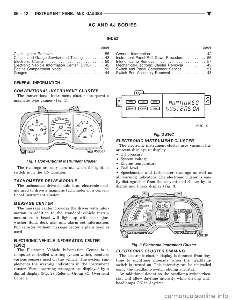
CONVENTIONAL INSTRUMENT CLUSTER
The conventional instrument cluster incorporates
magnetic type gauges (Fig. 1).
The readings are only accurate when the ignition
switch is in the ON position.
TACHOMETER DRIVE MODULE
The tachometer drive module is an electronic mod-
ule used to drive a magnetic tachometer in a conven-
tional instrument cluster.
MESSAGE CENTER
The message center provides the driver with infor-
mation in addition to the standard vehicle instru-
mentation. A bezel will light up with door ajar,
washer fluid, deck ajar and alarm set information.
For vehicles without message center a plain bezel is
used.
ELECTRONIC VEHICLE INFORMATION CENTER
(EVIC)
The Electronic Vehicle Information Center is a
computer controlled warning system which, monitors
various sensors used on the vehicle. The system sup-
plements the warning indicators in the instrument
cluster. Visual warning messages are displayed by a
digital display (Fig. 2). Refer to Group 8C, Overhead
Console.
ELECTRONIC INSTRUMENT CLUSTER
The electronic instrument cluster uses vacuum flu-
orescent displays to display:
² Oil pressure
² System voltage
² Engine temperature
² Fuel level
² Speedometer and tachometer readings as well as
all warning indicators. The electronic cluster is eas-
ily distinguished from the conventional cluster by its
digital and linear display (Fig. 3.
ELECTRONIC CLUSTER DIMMING
The electronic cluster display is dimmed from day-
time to nighttime intensity when the head]lamp
switch is turned on. This intensity can be controlled
using the headlamp switch sliding rheostat. An additional detent on the headlamp switch rheo-
stat will allow daytime intensity while driving with
headlamps ON in daytime.
Fig. 1 Conventional Instrument Cluster
Fig. 2 EVIC
Fig. 3 Electronic Instrument Cluster
8E - 42 INSTRUMENT PANEL AND GAUGES Ä
Page 535 of 2438
ELECTRONIC DIGITAL CLOCK
The electronic digital clock is in the radio. The
clock and radio each use the display panel built into
the radio. A digital readout indicates the time in
hours and minutes whenever the ignition switch is in
the ON or ACC position. When the ignition switch is in the ON or OFF po-
sition, or when the radio frequency is being dis-
played, time keeping is accurately maintained. The procedure for setting the clock varies slightly
with each radio. The correct procedure is described
under the individual radio operating instructions re-
ferred to in the Owner's manual supplied with the
vehicle.
WARNING LAMPS
The AG & AJ Body instrument clusters have warn-
ing lamps or indicators with the electronic cluster for
six different systems. These include low oil pressure,
check gauges, brake system, air bag, seat belt, mal-
function indicator (check engine) lamp.
CLUSTER AND GAUGE SERVICE AND TESTING
CAUTION: Disconnect negative battery cable, in en-
gine compartment, before servicing instrument
panel. When power is required for test purposes,
reconnect battery cable for test only. Disconnect negative battery cable after test and be-
fore continuing service procedures. It is not necessary to remove instrument cluster
from vehicle for gauge replacement. Gauges must be pulled straight out, when remov-
ing or pins may be damaged.
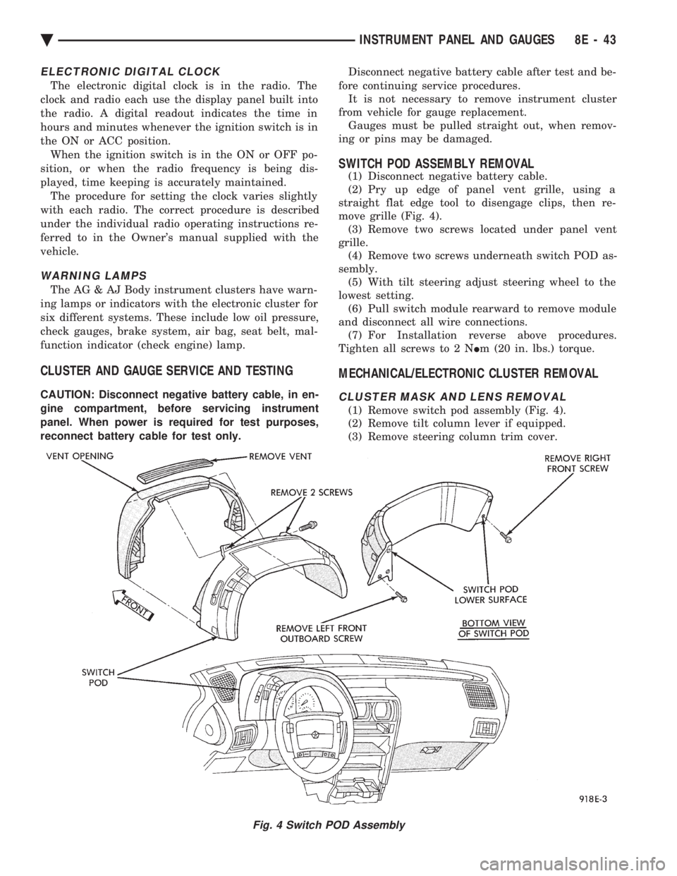
SWITCH POD ASSEMBLY REMOVAL
(1) Disconnect negative battery cable.
(2) Pry up edge of panel vent grille, using a
straight flat edge tool to disengage clips, then re-
move grille (Fig. 4). (3) Remove two screws located under panel vent
grille. (4) Remove two screws underneath switch POD as-
sembly. (5) With tilt steering adjust steering wheel to the
lowest setting. (6) Pull switch module rearward to remove module
and disconnect all wire connections. (7) For Installation reverse above procedures.
Tighten all screws to 2 N Im (20 in. lbs.) torque.
MECHANICAL/ELECTRONIC CLUSTER REMOVAL
CLUSTER MASK AND LENS REMOVAL
(1) Remove switch pod assembly (Fig. 4).
(2) Remove tilt column lever if equipped.
(3) Remove steering column trim cover.
Fig. 4 Switch POD Assembly
Ä INSTRUMENT PANEL AND GAUGES 8E - 43