trunk CHEVROLET DYNASTY 1993 Service Manual
[x] Cancel search | Manufacturer: CHEVROLET, Model Year: 1993, Model line: DYNASTY, Model: CHEVROLET DYNASTY 1993Pages: 2438, PDF Size: 74.98 MB
Page 123 of 2438
REAR LEVELING DIAGNOSTIC PROCEDURES
SELF-DIAGNOSTICS
A self-diagnostic procedure is available for the ser-
vice technician to use to detect system malfunctions.
BEFORE DIAGNOSTICS TEST
Check the 20 amp fuse (position W40) and the 30
amp circuit breaker (position W5) to be assured they
are functional components. Check all connectors that link the system into the
main body wiring harness. These include compressor,
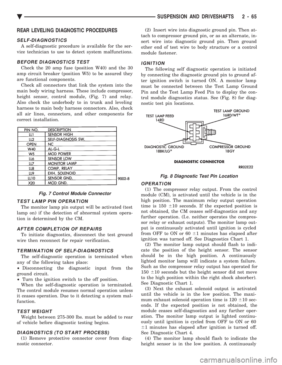
height sensor, control module, (Fig. 7) and relay.
Also check the underbody to in trunk and leveling
harness to main body harness connectors. Also, check
all air lines, connectors, and other components for
correct installation.
TEST LAMP PIN OPERATION
The monitor lamp pin output will be activated (test
lamp on) if the detection of abnormal system opera-
tion is determined by the CM.
AFTER COMPLETION OF REPAIRS
To initiate diagnostics, disconnect the test ground
wire then reconnect for repair verification.
TERMINATION OF SELF-DIAGNOSTICS
The self-diagnostic operation is terminated when
any of the following takes place:
² Disconnecting the diagnostic input from the
ground circuit.
² Turn the ignition switch to the off position.
When the self-diagnostic operation is terminated.
The control module resumes normal operation unless
it ceases operation. Due to it detecting a system mal-
function.
TEST WEIGHT
Weight between 275-300 lbs. must be added to rear
of vehicle before diagnostic testing begins.
DIAGNOSTICS (TO START PROCESS)
(1) Remove protective connector cover from diag-
nostic connector. (2) Insert wire into diagnostic ground pin. Then at-
tach to compressor ground pin, or as an alternate, in-
sert wire into diagnostic ground pin. Then ground
other end of test wire to body structure or a control
module fastener.
IGNITION
The following self diagnostic operation is initiated
by connecting the diagnostic ground pin to ground af-
ter ignition switch is turned ON. A monitor lamp
must be connected between the Test Lamp Ground
Pin and the Test Lamp Feed Pin to display the con-
trol module diagnostics status. See (Fig. 8) for diag-
nostic test pin locations.
OPERATION
(1) The compressor relay output. From the control
module (CM), is activated until the vehicle is in the
high position. The maximum relay output operation
time is 150 610 seconds. If the expected position is
not obtained, the CM ceases self-diagnostics and any
further operation. (I.e. neither operates the compres-
sor relay or exhaust outputs). The monitor lamp out-
put is continuously activated until ignition is cycled
from OFF to ON or 60 61 minutes has elapsed after
ignition was turned off. See Diagnostics Chart 1. (2) The monitor lamp output should flash to indi-
cate the position of the height sensor. The sensor
should be in the high position. A continuously
lighted monitor lamp will indicate a system failure.
Such as the compressor relay output has operated for
150 610 seconds but the height sensor did not move
to the high position within the right shock absorber).
See Diagnostic Chart 1. (3) Next the exhaust solenoid output is activated
until the vehicle is in the low position. The maxi-
mum exhaust solenoid operation time is 120 610 sec-
onds. If the expected position is not obtained, the
module ceases self-diagnostics and any further oper-
ation. The monitor lamp output is lighted continu-
ously until ignition is cycled from OFF to ON or 60
6 1 minutes has elapsed after ignition is turned off.
See Diagnostic Chart 4. (4) The monitor lamp should flash to indicate the
height sensor is in the low position. A continuouslyFig. 7 Control Module Connector
Fig. 8 Diagnostic Test Pin Location
Ä SUSPENSION AND DRIVESHAFTS 2 - 65
Page 130 of 2438
CONTROL MODULE
REMOVAL
(1) Disconnect negative battery cable.
(2) Remove right side trunk trim panel.
(3) Remove electrical connectors from control mod-
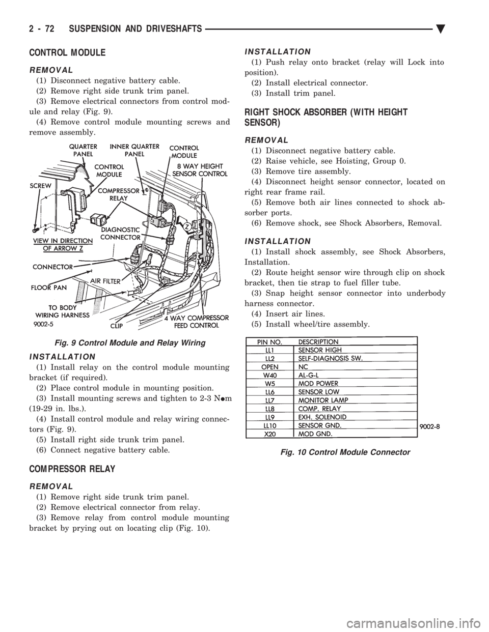
ule and relay (Fig. 9). (4) Remove control module mounting screws and
remove assembly.
INSTALLATION
(1) Install relay on the control module mounting
bracket (if required). (2) Place control module in mounting position.
(3) Install mounting screws and tighten to 2-3 N Im
(19-29 in. lbs.). (4) Install control module and relay wiring connec-
tors (Fig. 9). (5) Install right side trunk trim panel.
(6) Connect negative battery cable.
COMPRESSOR RELAY
REMOVAL
(1) Remove right side trunk trim panel.
(2) Remove electrical connector from relay.
(3) Remove relay from control module mounting
bracket by prying out on locating clip (Fig. 10).
INSTALLATION
(1) Push relay onto bracket (relay will Lock into
position). (2) Install electrical connector.
(3) Install trim panel.
RIGHT SHOCK ABSORBER (WITH HEIGHT
SENSOR)
REMOVAL
(1) Disconnect negative battery cable.
(2) Raise vehicle, see Hoisting, Group 0.
(3) Remove tire assembly.
(4) Disconnect height sensor connector, located on
right rear frame rail. (5) Remove both air lines connected to shock ab-
sorber ports. (6) Remove shock, see Shock Absorbers, Removal.
INSTALLATION
(1) Install shock assembly, see Shock Absorbers,
Installation. (2) Route height sensor wire through clip on shock
bracket, then tie strap to fuel filler tube. (3) Snap height sensor connector into underbody
harness connector. (4) Insert air lines.
(5) Install wheel/tire assembly.
Fig. 9 Control Module and Relay Wiring
Fig. 10 Control Module Connector
2 - 72 SUSPENSION AND DRIVESHAFTS Ä
Page 132 of 2438
FRONT AND REAR AIR SPRINGS
The front and rear air springs are essentially pneu-
matic cylinders that replace the steel coil springs.
The air filled springs allow the vehicle suspension
height to be adjusted for all weight conditions. The air springs allow for the reduction of spring
rates to improve vehicle ride characteristics.
FRONT/REAR SPRING SOLENOIDS
The front and rear solenoids control air flow in and
out of the front and rear springs. The Air Suspension
Control Module (ASCM) opens the solenoids when
the system requires air to be added to or exhausted
from the air springs. The solenoids operate at a cur-
rent draw range of 0.6 to 1.5 amps.
HEIGHT SENSOR
A magnetic switch type sensor. Located in the
right rear shock absorber and left and right front
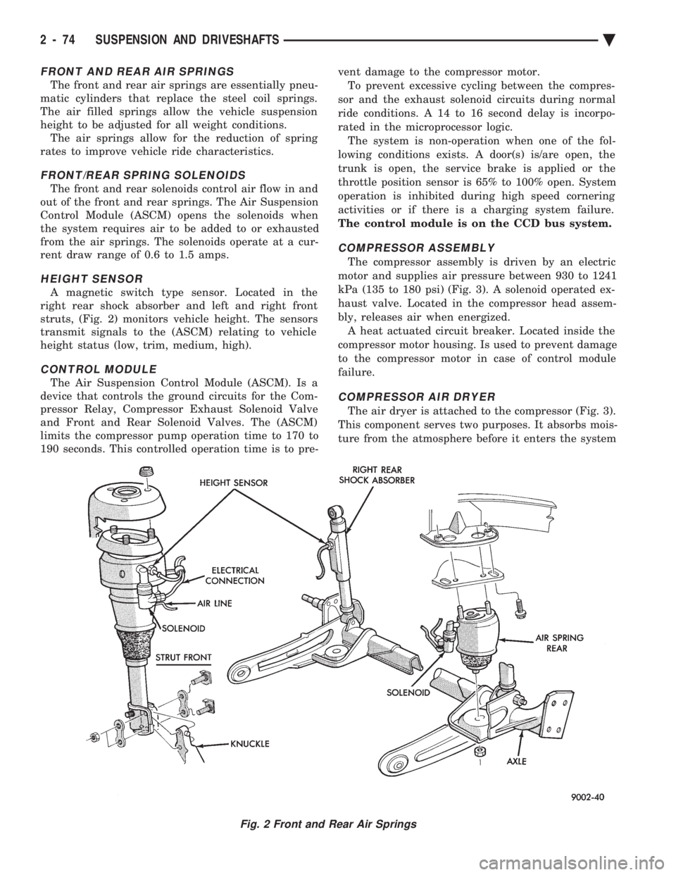
struts, (Fig. 2) monitors vehicle height. The sensors
transmit signals to the (ASCM) relating to vehicle
height status (low, trim, medium, high).
CONTROL MODULE
The Air Suspension Control Module (ASCM). Is a
device that controls the ground circuits for the Com-
pressor Relay, Compressor Exhaust Solenoid Valve
and Front and Rear Solenoid Valves. The (ASCM)
limits the compressor pump operation time to 170 to
190 seconds. This controlled operation time is to pre- vent damage to the compressor motor.
To prevent excessive cycling between the compres-
sor and the exhaust solenoid circuits during normal
ride conditions. A 14 to 16 second delay is incorpo-
rated in the microprocessor logic. The system is non-operation when one of the fol-
lowing conditions exists. A door(s) is/are open, the
trunk is open, the service brake is applied or the
throttle position sensor is 65% to 100% open. System
operation is inhibited during high speed cornering
activities or if there is a charging system failure.
The control module is on the CCD bus system.
COMPRESSOR ASSEMBLY
The compressor assembly is driven by an electric
motor and supplies air pressure between 930 to 1241
kPa (135 to 180 psi) (Fig. 3). A solenoid operated ex-
haust valve. Located in the compressor head assem-
bly, releases air when energized. A heat actuated circuit breaker. Located inside the
compressor motor housing. Is used to prevent damage
to the compressor motor in case of control module
failure.
COMPRESSOR AIR DRYER
The air dryer is attached to the compressor (Fig. 3).
This component serves two purposes. It absorbs mois-
ture from the atmosphere before it enters the system
Fig. 2 Front and Rear Air Springs
2 - 74 SUSPENSION AND DRIVESHAFTS Ä
Page 136 of 2438
(3) Check solenoid to volume canister joint.
² Front strut to solenoid valve connection.
² Rear spring to solenoid valve connection.
(4) Check air line for ruptures, cuts, splits or heat
damage. Use a soap and water solution or a liquid de-
veloped for leak detection.
SYSTEM OPERATION
ENGINE RUN OPERATION
The system will compensate for load
addition/removal when.
² The trunk and all doors are closed.
² The engine speed exceeds 600 R.P.M.
² Throttle angle is less than 65 degrees.
² The brake is not applied.
² You are not cornering above 10 mph.
² There is not a charging system problem with the
vehicle.
ENGINE OFF OPERATION
After passengers/load is removed from the vehicle
the system will correct the vehicle attitude after:
² The trunk and all doors are closed.
² The ignition switch is in the OFF position.
Opening the a door or trunk wakes up the body
computer and the air suspension module. The air
suspension system is now capable of leveling, if
required.
LONG TERM IGNITION OFF OPERATION
The system is capable of one an additional leveling
cycle. After 2 continuous hours of ignition key off and
no door open or trunk open activities. This feature is
implemented to eliminate possible ice freeze-up be-
tween the tire and the inner fender shield.
SYSTEM OPERATION INHIBITORS
The air suspension system is inhibited when:
² The trunk is open.
² A door(s) is/are open.
² The brake pedal is engaged.
² The throttle is at the wide open position.
² The charging system fails.
The maximum compressor pump or exhaust
time is 3 minutes.
SYSTEM FAILURES
Vehicles equipped with air suspension and overhead
console. Will alert the driver of an air suspension
system malfunction. A warning Check Air Suspension
will appear on the overhead console screen.
SAFETY CONCERNS
WARNING: REAR AIR SPRINGS MUST BE DEFLATED
BEFORE BEING REMOVED FROM THE VEHICLE.
WARNING: OPEN TRUNK, OR DOOR(S) OR REMOVE
GROUND STRAP FROM BATTERY BEFORE HOIST-
ING OR JACKING A VEHICLE DURING MECHANICAL
REPAIRS.
WARNING: IF THE VEHICLE NEEDS SERVICE OR
REPAIR OF THE REAR SHOCK ABSORBERS OR
REAR AXLE PIVOT BUSHINGS. THE REAR AIR
SPRINGS MUST HAVE THE AIR PRESSURE RE-
MOVED BEFORE THE VEHICLE CAN BE SERVICED
SAFELY.
SHIPPING MODE
(1) Removing shipping height signal for customer
use.
² Use DRB II tester and 1991 Chassis (Air Suspen-
sion) service cartridge.
² Follow DRB II requirements to cancel shipping
height message in the body computer.
² Connect the Ignition Off Draw (I.O.D.) circuit.
The connection of the IOD circuit will cancel
the Shipping height signal. (2) Return to shipping height.
² Set shipping command in the body computer using
the DRB II and the 1991 Chassis (Air suspension)
service cartridge.
² Disconnect the I.O.D. connector.
DIAGNOSIS
INITIAL DIAGNOSTIC CHECK
(1) Check for blown or missing fuses.
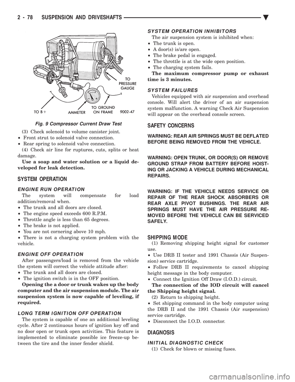
Fig. 9 Compressor Current Draw Test
2 - 78 SUSPENSION AND DRIVESHAFTS Ä
Page 137 of 2438
(2) Check all connectors for correct assembly. Check
all connectors for incorrectly installed termi-
nals. (3) Check pin #21 for minimum of 9.5 volts.
(4) Check pin #20 for minimum of 9.5 volts (with
ignition key on). (5) Check voltage at pins #5 and #16. The measure-
ment should exceed 0 volts. (6) Check pin #19 for continuity.
(7) The engine speed should exceed 680 rpm during
idle. All doors and trunk must be closed for the
system to function.
DIAGNOSTICS PROCEDURES
(1) Use the D.R.B. II tester and the 1991 air suspen-
sion diagnostic service cartridge to begin the trouble-
shooting process. (2) Use the D.R.B. mating connector under the dash
(drivers side) to plug-in the D.R.B. II test connector
(Fig. 10). (3) The tester will conduct a complete check of the
suspension system status. (4) The tester will list the steps to follow to access
and diagnose the failure. (5) A Volt/Ohm meter can be used for some diagnos-
tic testing.
HEIGHT SENSOR CHECK
If a sensor signal/signals are missing. Follow the
repair procedure listed below. (1) Check ground circuit continuity. (Remember
front and rear grounds are on different circuits. (2) For front ground circuit continuity check circuit
S 33. (3) For rear ground circuit continuity check circuit
X20. (4) Refer to control module pin out chart and wiring
diagram (see Group 8F in wiring diagram manual) for
individual circuit details. (5) If open circuits are not found replace the compo-
nent. Complete circuit testing and connector assem-
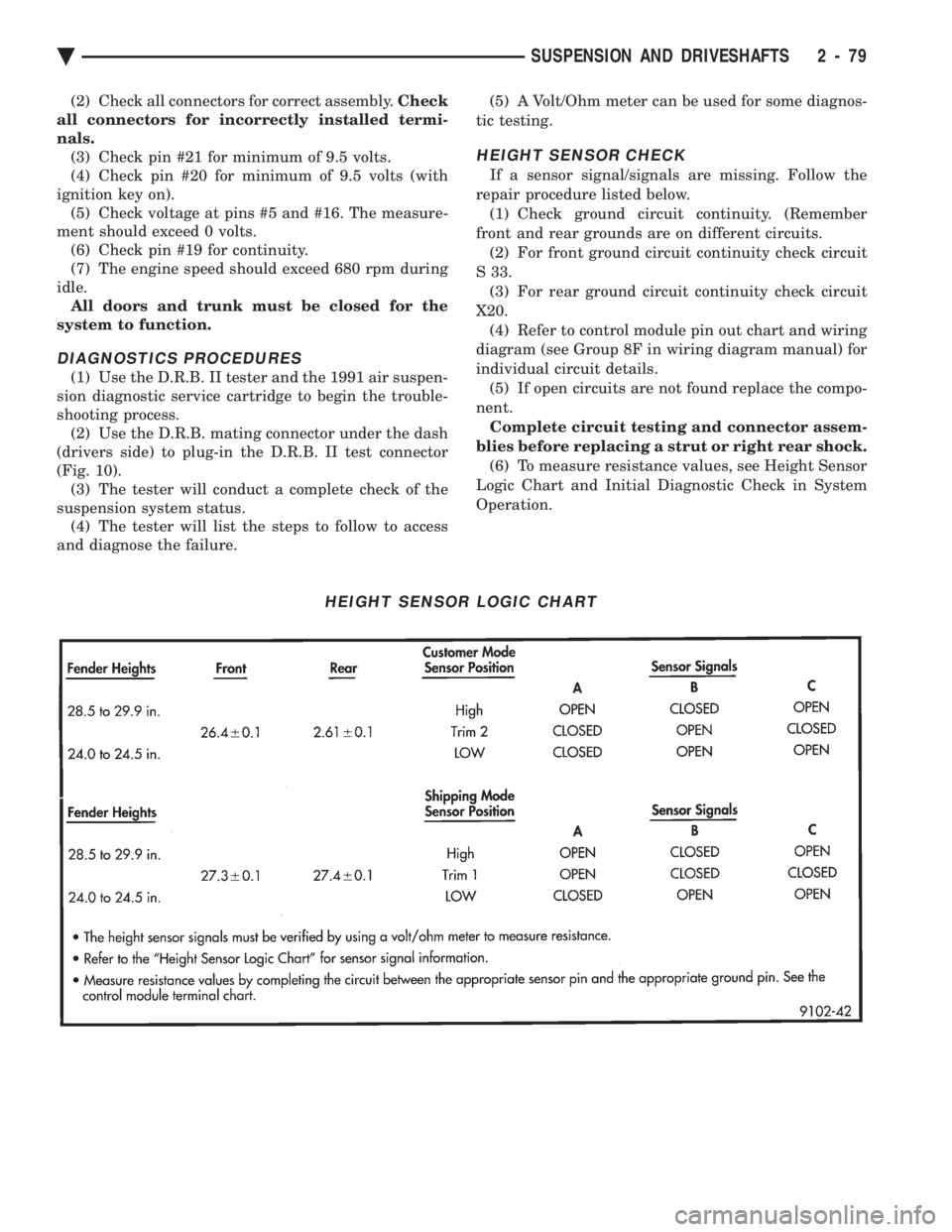
blies before replacing a strut or right rear shock. (6) To measure resistance values, see Height Sensor
Logic Chart and Initial Diagnostic Check in System
Operation.
HEIGHT SENSOR LOGIC CHART
Ä SUSPENSION AND DRIVESHAFTS 2 - 79
Page 143 of 2438
SERVICE PROCEDURES
CONTROL MODULE (ASCM)
REMOVAL (1) Disconnect negative battery cable.
(2) Remove right side trunk trim panel.
(3) Remove electrical connectors from control mod-
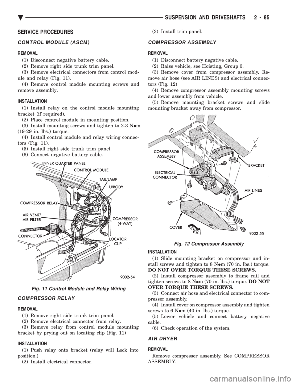
ule and relay (Fig. 11). (4) Remove control module mounting screws and
remove assembly.
INSTALLATION
(1) Install relay on the control module mounting
bracket (if required). (2) Place control module in mounting position.
(3) Install mounting screws and tighten to 2-3 N Im
(19-29 in. lbs.) torque. (4) Install control module and relay wiring connec-
tors (Fig. 11). (5) Install right side trunk trim panel.
(6) Connect negative battery cable.
COMPRESSOR RELAY
REMOVAL
(1) Remove right side trunk trim panel.
(2) Remove electrical connector from relay.
(3) Remove relay from control module mounting
bracket by prying out on locating clip (Fig. 11)
INSTALLATION (1) Push relay onto bracket (relay will Lock into
position.) (2) Install electrical connector. (3) Install trim panel.
COMPRESSOR ASSEMBLY
REMOVAL
(1) Disconnect battery negative cable.
(2) Raise vehicle, see Hoisting, Group 0.
(3) Remove cover from compressor assembly. Re-
move air hose (see AIR LINES) and electrical connec-
tors (Fig. 12) (4) Remove compressor assembly mounting screws
and lower assembly from vehicle. (5) Remove mounting bracket screws and slide
mounting bracket away from compressor.
INSTALLATION (1) Slide mounting bracket on compressor and in-
stall screws and tighten to 8 N Im (70 in. lbs.) torque.
DO NOT OVER TORQUE THESE SCREWS. (2) Install compressor assembly to frame rail and
tighten screws to 8 N Im (70 in. lbs.) torque. DO NOT
OVER TORQUE THESE SCREWS. (3) Connect air hose and electrical connector to com-
pressor assembly. (4) Install cover on compressor assembly and tighten
screws to 6 N Im (40 in. lbs.) torque.
(5) Lower vehicle and connect battery negative
cable. (6) Check operation of the system.
AIR DRYER
REMOVAL
Remove compressor assembly. See COMPRESSOR
ASSEMBLY.
Fig. 11 Control Module and Relay Wiring
Fig. 12 Compressor Assembly
Ä SUSPENSION AND DRIVESHAFTS 2 - 85
Page 381 of 2438
IGNITION OFF DRAW (IOD)
GENERAL INFORMATION
A normal electrical system will draw from 5 to 30
milliamperes from the battery. This is with the ignition
in the OFF position, and all non-ignition controlled cir-
cuits in proper working order. The amount of IOD will
depend on body model and electrical components. A ve-
hicle that has not been operated for an extended period
of approximately 20 days may discharge the battery to
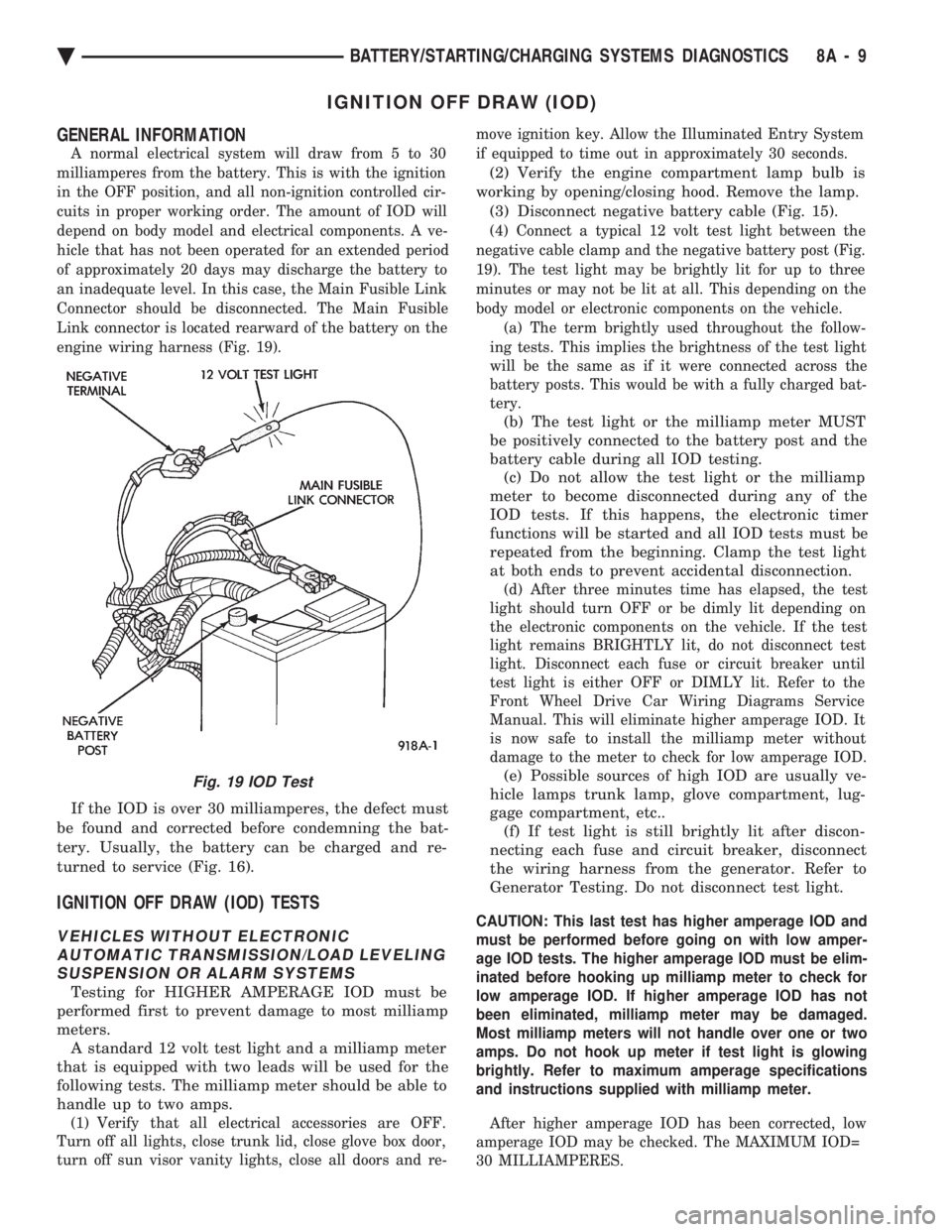
an inadequate level. In this case, the Main Fusible Link
Connector should be disconnected. The Main Fusible
Link connector is located rearward of the battery on the
engine wiring harness (Fig. 19).
If the IOD is over 30 milliamperes, the defect must
be found and corrected before condemning the bat-
tery. Usually, the battery can be charged and re-
turned to service (Fig. 16).
IGNITION OFF DRAW (IOD) TESTS
VEHICLES WITHOUT ELECTRONIC AUTOMATIC TRANSMISSION/LOAD LEVELINGSUSPENSION OR ALARM SYSTEMS
Testing for HIGHER AMPERAGE IOD must be
performed first to prevent damage to most milliamp
meters. A standard 12 volt test light and a milliamp meter
that is equipped with two leads will be used for the
following tests. The milliamp meter should be able to
handle up to two amps.
(1) Verify that all electrical accessories are OFF.
Turn off all lights, close trunk lid, close glove box door,
turn off sun visor vanity lights, close all doors and re- move ignition key. Allow the Illuminated Entry System
if equipped to time out in approximately 30 seconds.
(2) Verify the engine compartment lamp bulb is
working by opening/closing hood. Remove the lamp. (3) Disconnect negative battery cable (Fig. 15).
(4) Connect a typical 12 volt test light between the
negative cable clamp and the negative battery post (Fig.
19). The test light may be brightly lit for up to three
minutes or may not be lit at all. This depending on the
body model or electronic components on the vehicle. (a) The term brightly used throughout the follow-
ing tests. This implies the brightness of the test light
will be the same as if it were connected across the
battery posts. This would be with a fully charged bat-
tery.
(b) The test light or the milliamp meter MUST
be positively connected to the battery post and the
battery cable during all IOD testing. (c) Do not allow the test light or the milliamp
meter to become disconnected during any of the
IOD tests. If this happens, the electronic timer
functions will be started and all IOD tests must be
repeated from the beginning. Clamp the test light
at both ends to prevent accidental disconnection.
(d) After three minutes time has elapsed, the test
light should turn OFF or be dimly lit depending on
the electronic components on the vehicle. If the test
light remains BRIGHTLY lit, do not disconnect test
light. Disconnect each fuse or circuit breaker until
test light is either OFF or DIMLY lit. Refer to the
Front Wheel Drive Car Wiring Diagrams Service
Manual. This will eliminate higher amperage IOD. It
is now safe to install the milliamp meter without
damage to the meter to check for low amperage IOD.
(e) Possible sources of high IOD are usually ve-
hicle lamps trunk lamp, glove compartment, lug-
gage compartment, etc.. (f) If test light is still brightly lit after discon-
necting each fuse and circuit breaker, disconnect
the wiring harness from the generator. Refer to
Generator Testing. Do not disconnect test light.
CAUTION: This last test has higher amperage IOD and
must be performed before going on with low amper-
age IOD tests. The higher amperage IOD must be elim-
inated before hooking up milliamp meter to check for
low amperage IOD. If higher amperage IOD has not
been eliminated, milliamp meter may be damaged.
Most milliamp meters will not handle over one or two
amps. Do not hook up meter if test light is glowing
brightly. Refer to maximum amperage specifications
and instructions supplied with milliamp meter.
After higher amperage IOD has been corrected, low
amperage IOD may be checked. The MAXIMUM IOD=
30 MILLIAMPERES.
Fig. 19 IOD Test
Ä BATTERY/STARTING/CHARGING SYSTEMS DIAGNOSTICS 8A - 9
Page 382 of 2438
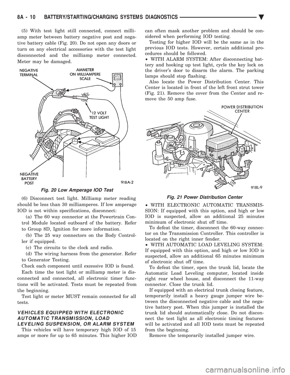
(5) With test light still connected, connect milli-
amp meter between battery negative post and nega-
tive battery cable (Fig. 20). Do not open any doors or
turn on any electrical accessories with the test light
disconnected and the milliamp meter connected.
Meter may be damaged.
(6) Disconnect test light. Milliamp meter reading
should be less than 30 milliamperes. If low amperage
IOD is not within specifications, disconnect: (a) The 60 way connector at the Powertrain Con-
trol Module located outboard of the battery. Refer
to Group 8D, Ignition for more information. (b) The 25 way connectors on the Body Control-
ler if equipped. (c) The circuits to the clock and radio.
(d) The wiring harness from the generator. Refer
to Generator Testing.
Check each component until excessive IOD is found.
Each time the test light or milliamp meter is dis-
connected and connected, all electronic timer func-
tions will be activated. Tests must be repeated from
the beginning. Test light or meter MUST remain connected for all
tests.
VEHICLES EQUIPPED WITH ELECTRONIC AUTOMATIC TRANSMISSION, LOADLEVELING SUSPENSION, OR ALARM SYSTEM
This vehicles will have temporary high IOD of 15
amps or more for up to 65 minutes. This higher IOD can often mask another problem and should be con-
sidered when performing IOD testing. Testing for higher IOD will be the same as in the
previous IOD tests. However, certain additional pro-
cedures should be followed.
² WITH ALARM SYSTEM: After disconnecting bat-
tery and hooking up test light, cycle the key lock on
the driver's door to disarm the alarm. The parking
lamps should stop flashing. Also locate the Power Distribution Center. This
Center is located in front of the left front strut tower
(Fig. 21). Remove the cover from the Center and re-
move the 50 amp fuse.
² WITH ELECTRONIC AUTOMATIC TRANSMIS-
SION: If equipped with this option, and high or low
IOD is suspected, allow an additional 25 minutes
minimum of electronic shut off time. To defeat the timer, disconnect the 60-way connec-
tor on the Transmission Controller. This controller is
located on the right inner fender.
² WITH AUTOMATIC LOAD LEVELING SYSTEM:
If equipped with this option, and high or low IOD is
suspected, allow an additional 65 minutes minimum
of electronic shut off time. To defeat the timer, open the trunk lid, locate the
Automatic Load Leveling computer, located inside
right rear wheel house, and disconnect the 11-way
connector. Close the trunk lid. If equipped with an electrical trunk closing feature,
temporarily install a heavy gauge jumper wire be-
tween the disconnected negative cable and the nega-
tive battery post. When this jumper is installed the
trunk lid should automatically close. Do not discon-
nect the test light as all electronic timing features
will be activated and all IOD tests must be repeated
from the beginning. Remove the temporarily installed jumper wire.
Fig. 20 Low Amperage IOD Test
Fig. 21 Power Distribution Center
8A - 10 BATTERY/STARTING/CHARGING SYSTEMS DIAGNOSTICS Ä
Page 424 of 2438
VISUAL MESSAGES
Following are the visual messages and the condi-
tions under which, the messages will be given:
² Keys in ignition
² Exterior lamps on
These messages will appear if the conditions are
present and the driver's door is open while the igni-
tion switch is in the OFF, LOCK, or ACC positions.
A tone will sound until the condition is corrected or
the door is closed.
² Passenger door ajar
² Driver door ajar
² Trunk ajar
² Park brake engaged
² Right rear door ajar
² Left rear door ajar
These messages will appear if a condition is de-
tected after the vehicle is in motion. When the con-
dition is corrected, a short tone will sound to
acknowledge the action. LOW OIL PRESSURE
If this message is displayed while the vehicle is at
cruising speeds, immediate attention is required. If
this message appears at idle speed, increase the idle
speed and the message should go off. If the message
remains on, immediate attention is required. ENGINE TEMP CRITICAL
This message appears when a sensor has determined
that the engine coolant is overheating. If this message
comes on and stays on, immediate action is required.
COOLANT LEVEL LOW
LOW FUEL LEVEL
LOW BRAKE FLUID
WASHER FLUID LOW
These messages will appear if a continuous warn-
ing condition is detected while the engine is running.
Inspection is required. To clear this message from
the display, after the condition is corrected, the igni-
tion switch must be turned OFF. CHECK TRANS
This message will appear if a continuous warning
condition is detected while the engine is running. Im-
mediate attention is recommended. To clear this mes-
sage from the display, after the condition has been
corrected, the ignition switch must be turned OFF. VOLTAGE IMPROPER
This message will appear if a continuous warning
condition is detected. Immediate attention is re-
quired. To clear this message from the display, after
the condition has been corrected, the ignition switch
must be turned OFF. TURN SIGNAL ON
This message will appear if the turn signal is left
on while vehicle speed is over 15 mph and the vehi-
cle has traveled over one-half mile. FASTEN SEAT BELTS An intermittent chime tone will sound for several
seconds if the seat belt is not fastened. CHK ENGINE OIL LEVEL
If this message is delivered, a check of the engine
oil dipstick is suggested. To clear this message, after
the condition is corrected, the ignition switch must
be turned OFF. HEADLAMP OUT
BRAKE LAMP OUT
TAIL LAMP OUT
These conditions are monitored only when the lamps
are on. The message will remain, even after the lamp is
replaced, until the lamp is turned on and operates.
SERVICE REMINDER
The maintenance reminder statement is programmed
to provide general information only. Refer to Group 0,
Lubrication & Maintenance for specific vehicle require-
ments.
The service reminder message is displayed at 7,500
miles or 12 months intervals, which ever comes first. MONITORED SYSTEMS OK
If there is no warning condition to report, the mes-
sage Monitored Systems OK is displayed (Fig. 2).
AUTOMATIC CALIBRATION SET PROCEDURE
The engine compartment node will continuously
and automatically recalibrate the compass under nor-
mal driving conditions. As long as the vehicle is
turning, the engine compartment node will record
new compass data. This new data will be used to
recalibrate the compass at a rate of at least once per
full (360 degree) turn of the vehicle. Automatic cali-
bration does not require operator interface.
MANUAL CALIBRATION SET PROCEDURE
Manual compass calibration has been replaced by
automatic calibration set procedure. The manual cal-
ibration set procedure is available, but no longer
serves any useful purpose.
EVIC SELF CHECK DIAGNOSTICS
Ignition switch ON, the EVIC not displaying any
message, may imply a system failure and not an
EVIC failure. Turn the ignition OFF, close all vehi-
cle doors and wait at least 60 seconds before begin-
ning test. Turn ignition switch to the ON position.
Pressing the TEMP, FUEL and INFO buttons at the
same time shall provide the visual message MOD-
ULE SELF CHECK for two seconds. Following at
two second interval there will be messages:
² E2-0 SELF CHECK
² E3-0 SELF CHECK
² END OF SELF CHECK
Showing the microcomputer is working properly.
When the self check mode and message shows:
² E2-1
² E3-2
This would show a fault exists in the EVIC's micro-
computer and the EVIC should be replaced (Fig. 3).
8C - 8 OVERHEAD CONSOLE Ä
Page 431 of 2438
VISUAL MESSAGES
Following are the visual messages and the condi-
tions under which, the messages will be given:
² Keys in ignition
² Exterior lamps on
These messages will appear if the conditions are
present and the driver's door is open while the igni-
tion switch is in the OFF, LOCK, or ACC positions.
A tone will sound until the condition is corrected or
the door is closed.
² Passenger door ajar
² Driver door ajar
² Trunk ajar
² Park brake engaged
² Right rear door ajar
² Left rear door ajar
These messages will appear if a condition is de-
tected after the vehicle is in motion. When the con-
dition is corrected, a short tone will sound to
acknowledge the action. LOW OIL PRESSURE
If this message is displayed while the vehicle is at
cruising speeds, immediate attention is required. If
this message appears at idle speed, increase the idle
speed and the message should go off. If the message
remains on, immediate attention is required. ENGINE TEMP CRITICAL
This message appears when a sensor has deter-
mined that the engine coolant is overheating. If this
message comes on and stays on, immediate action is
required. COOLANT LEVEL LOW
LOW FUEL LEVEL
LOW BRAKE FLUID WASHER FLUID LOW
These messages will appear if a continuous warn-
ing condition is detected while the engine is running.
Inspection is required. To clear this message from
the display, after the condition is corrected, the igni-
tion switch must be turned OFF. CHECK TRANS
This message will appear if a continuous warning
condition is detected while the engine is running. Im-
mediate attention is recommended. To clear this mes-
sage from the display, after the condition has been
corrected, the ignition switch must be turned OFF. VOLTAGE IMPROPER
This message will appear if a continuous warning
condition is detected. Immediate attention is re-
quired. To clear this message from the display, after
the condition has been corrected, the ignition switch
must be turned OFF. TURN SIGNAL ON
This message will appear if the turn signal is left
on while vehicle speed is over 15 mph and the vehi-
cle has traveled over one-half mile. FASTEN SEAT BELTS
An intermittent chime tone will sound for several
seconds if the seat belt is not fastened. CHK ENGINE OIL LEVEL
If this message is delivered, a check of the engine
oil dipstick is suggested. To clear this message, after
the condition is corrected, the ignition switch must
be turned OFF. HEADLAMP OUT
BRAKE LAMP OUT
TAIL LAMP OUT
These conditions are monitored only when the
lamps are on. The message will remain, even after
the lamp is replaced, until the lamp is turned on and
operates. SERVICE REMINDER
The maintenance reminder statement is pro-
grammed to provide general information only. Refer
to Group 0, Lubrication & Maintenance for specific
vehicle requirements. The service reminder message is displayed at 7,500
miles or 12 months intervals, which ever comes first. MONITORED SYSTEMS OK
If there is no warning condition to report, the mes-
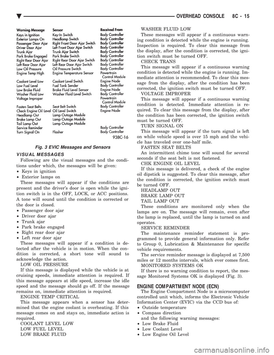
sage Monitored Systems OK is displayed (Fig. 3).
ENGINE COMPARTMENT NODE (ECN)
The Engine Compartment Node is a microcomputer
controlled unit which, informs the Electronic Vehicle
Information Center (EVIC) via the CCD bus of:
² Outside temperature
² Compass direction
and the following warning messages:
² Low Brake Fluid
² Low Coolant Level
² Low Engine Oil Level
Fig. 3 EVIC Messages and Sensors
Ä OVERHEAD CONSOLE 8C - 15