brakes CHEVROLET DYNASTY 1993 Service Manual
[x] Cancel search | Manufacturer: CHEVROLET, Model Year: 1993, Model line: DYNASTY, Model: CHEVROLET DYNASTY 1993Pages: 2438, PDF Size: 74.98 MB
Page 269 of 2438
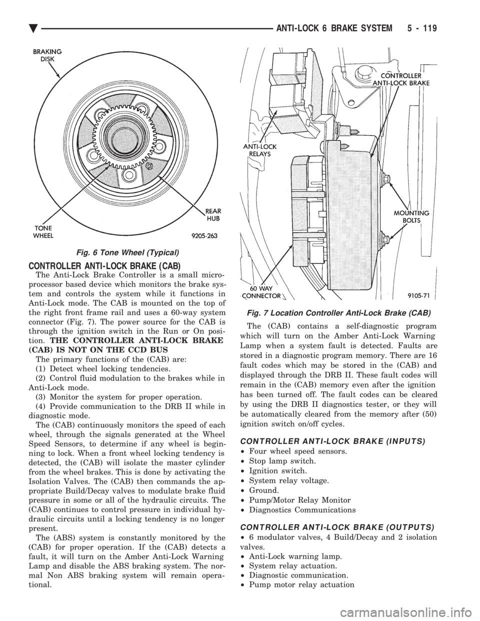
CONTROLLER ANTI-LOCK BRAKE (CAB)
The Anti-Lock Brake Controller is a small micro-
processor based device which monitors the brake sys-
tem and controls the system while it functions in
Anti-Lock mode. The CAB is mounted on the top of
the right front frame rail and uses a 60-way system
connector (Fig. 7). The power source for the CAB is
through the ignition switch in the Run or On posi-
tion. THE CONTROLLER ANTI-LOCK BRAKE
(CAB) IS NOT ON THE CCD BUS The primary functions of the (CAB) are:
(1) Detect wheel locking tendencies.
(2) Control fluid modulation to the brakes while in
Anti-Lock mode. (3) Monitor the system for proper operation.
(4) Provide communication to the DRB II while in
diagnostic mode. The (CAB) continuously monitors the speed of each
wheel, through the signals generated at the Wheel
Speed Sensors, to determine if any wheel is begin-
ning to lock. When a front wheel locking tendency is
detected, the (CAB) will isolate the master cylinder
from the wheel brakes. This is done by activating the
Isolation Valves. The (CAB) then commands the ap-
propriate Build/Decay valves to modulate brake fluid
pressure in some or all of the hydraulic circuits. The
(CAB) continues to control pressure in individual hy-
draulic circuits until a locking tendency is no longer
present. The (ABS) system is constantly monitored by the
(CAB) for proper operation. If the (CAB) detects a
fault, it will turn on the Amber Anti-Lock Warning
Lamp and disable the ABS braking system. The nor-
mal Non ABS braking system will remain opera-
tional. The (CAB) contains a self-diagnostic program
which will turn on the Amber Anti-Lock Warning
Lamp when a system fault is detected. Faults are
stored in a diagnostic program memory. There are 16
fault codes which may be stored in the (CAB) and
displayed through the DRB II. These fault codes will
remain in the (CAB) memory even after the ignition
has been turned off. The fault codes can be cleared
by using the DRB II diagnostics tester, or they will
be automatically cleared from the memory after (50)
ignition switch on/off cycles.
CONTROLLER ANTI-LOCK BRAKE (INPUTS)
² Four wheel speed sensors.
² Stop lamp switch.
² Ignition switch.
² System relay voltage.
² Ground.
² Pump/Motor Relay Monitor
² Diagnostics Communications
CONTROLLER ANTI-LOCK BRAKE (OUTPUTS)
²6 modulator valves, 4 Build/Decay and 2 isolation
valves.
² Anti-Lock warning lamp.
² System relay actuation.
² Diagnostic communication.
² Pump motor relay actuation
Fig. 6 Tone Wheel (Typical)
Fig. 7 Location Controller Anti-Lock Brake (CAB)
Ä ANTI-LOCK 6 BRAKE SYSTEM 5 - 119
Page 271 of 2438
Lamp Relay opens the Anti-Lock Warning Lamp Re-
lay switch. This breaks the ground path to the Am-
ber Anti-Lock Warning Lamp and the light is turned
off. The (CAB) by itself, also has the ability to turn on
the Amber Anti-Lock Warning Lamp. The (CAB) can
turn on the Amber Anti-Lock Warning Lamp by pro-
viding a ground at pin 15.
ANTI-LOCK WARNING LAMP ON
System Relay and Anti-Lock Warning Lamp
Relay De-Energized. When the Amber Anti-Lock Warning Lamp is on,
there is no electrical current flow from the (CAB) at
pin 57. The System Relay coil is NOT energized. No
electrical current flows to pin 47 and 41 (modulator
valve power), or to the Anti-Lock Warning Lamp Re-
lay coil. Thus, the Amber Anti-Lock Warning Lamp
is not energized. The Amber Anti-Lock Warning Lamp is grounded through the Anti-Lock Warning
Lamp Relay contacts. The Amber Anti-Lock Warning
Lamp is turned on.
HYDRAULIC CIRCUITS AND VALVE OPERATION
Through the following operation descriptions and
diagrams. The function of the various hydraulic con-
trol valves in the ABS system will be described. The
fluid control valves mentioned below, control the flow
of pressurized brake fluid to the wheel brakes during
the different modes of Anti-Lock braking. For explanation purposes we will assume all speed
sensors are sending the same wheel speed informa-
tion, requiring the same hydraulic fluid modulation
at the same rate.
NORMAL BRAKING
ISOLATION VALVES
Open to primary and secondary master cylinder
fluid supply (Fig. 1)
BUILD/DECAY VALVES Closed (Fig. 1)
The brake pedal is applied. The travel of the brake
pedal closes primary and secondary circuits from the
master cylinder fluid supply. Brake fluid from the
primary and secondary circuits flows through the
open isolation valves, through the build/decay valves
to the wheel brakes.
ABS BRAKING-BUILD PRESSURE
ISOLATION VALVES
Closed, isolating wheel brakes from master cylin-
der primary and secondary fluid supply. Through
open build valves (Fig. 2).
BUILD/DECAY VALVES Open (Fig. 2)
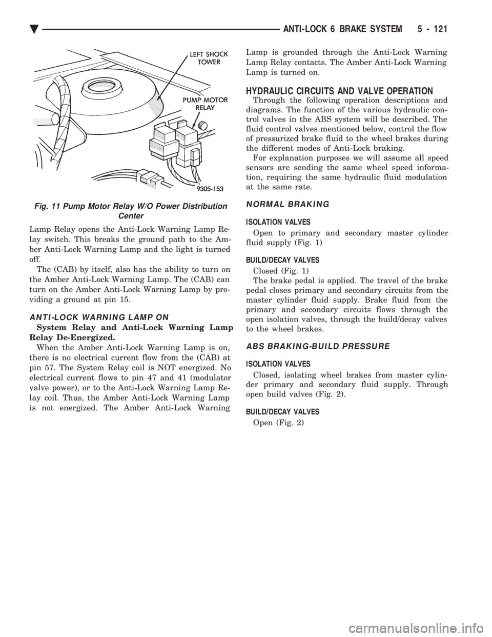
Fig. 11 Pump Motor Relay W/O Power Distribution Center
Ä ANTI-LOCK 6 BRAKE SYSTEM 5 - 121
Page 273 of 2438
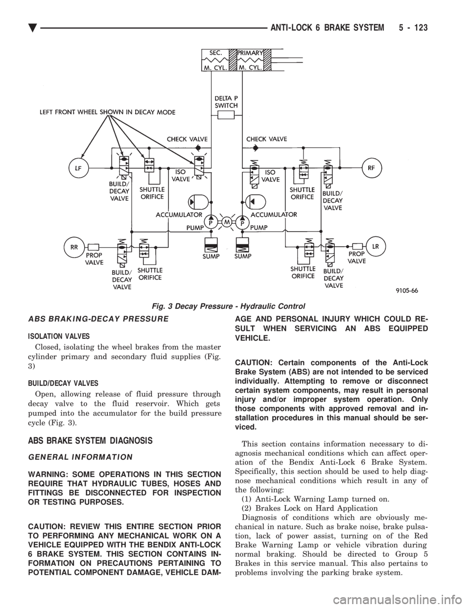
ABS BRAKING-DECAY PRESSURE
ISOLATION VALVES Closed, isolating the wheel brakes from the master
cylinder primary and secondary fluid supplies (Fig.
3)
BUILD/DECAY VALVES
Open, allowing release of fluid pressure through
decay valve to the fluid reservoir. Which gets
pumped into the accumulator for the build pressure
cycle (Fig. 3).
ABS BRAKE SYSTEM DIAGNOSIS
GENERAL INFORMATION
WARNING: SOME OPERATIONS IN THIS SECTION
REQUIRE THAT HYDRAULIC TUBES, HOSES AND
FITTINGS BE DISCONNECTED FOR INSPECTION
OR TESTING PURPOSES.
CAUTION: REVIEW THIS ENTIRE SECTION PRIOR
TO PERFORMING ANY MECHANICAL WORK ON A
VEHICLE EQUIPPED WITH THE BENDIX ANTI-LOCK
6 BRAKE SYSTEM. THIS SECTION CONTAINS IN-
FORMATION ON PRECAUTIONS PERTAINING TO
POTENTIAL COMPONENT DAMAGE, VEHICLE DAM- AGE AND PERSONAL INJURY WHICH COULD RE-
SULT WHEN SERVICING AN ABS EQUIPPED
VEHICLE.
CAUTION: Certain components of the Anti-Lock
Brake System (ABS) are not intended to be serviced
individually. Attempting to remove or disconnect
certain system components, may result in personal
injury and/or improper system operation. Only
those components with approved removal and in-
stallation procedures in this manual should be ser-
viced.
This section contains information necessary to di-
agnosis mechanical conditions which can affect oper-
ation of the Bendix Anti-Lock 6 Brake System.
Specifically, this section should be used to help diag-
nose mechanical conditions which result in any of
the following: (1) Anti-Lock Warning Lamp turned on.
(2) Brakes Lock on Hard Application
Diagnosis of conditions which are obviously me-
chanical in nature. Such as brake noise, brake pulsa-
tion, lack of power assist, turning on of the Red
Brake Warning Lamp or vehicle vibration during
normal braking. Should be directed to Group 5
Brakes in this service manual. This also pertains to
problems involving the parking brake system.
Fig. 3 Decay Pressure - Hydraulic Control
Ä ANTI-LOCK 6 BRAKE SYSTEM 5 - 123
Page 277 of 2438
WARNING: WHEN BLEEDING THE MODULATOR
ASSEMBLY WEAR SAFETY GLASSES. A CLEAR
BLEED TUBE MUST BE ATTACHED TO THE
BLEEDER SCREWS AND SUBMERGED IN A CLEAR
CONTAINER FILLED PART WAY WITH CLEAN
BRAKE FLUID. DIRECT THE FLOW OF BRAKE
FLUID AWAY FROM THE PAINTED SURFACES OF
THE VEHICLE. BRAKE FLUID AT HIGH PRESSURE
MAY COME OUT OF THE BLEEDER SCREWS,
WHEN OPENED.
When bleeding the Modulator Assembly. The fol-
lowing bleeding sequence MUSTbe followed to in-
sure complete and adequate bleeding of the brakes
hydraulic system. The Modulator Assembly can be
bled using a Manual bleeding procedure or standard
Pressure Bleeding Equipment. If the brake system is to be bled using pressure
bleeding equipment. Refer to Bleeding Brake System,
in the Service Adjustments section at the beginning
of this group, for proper equipment usage and proce-
dures.
MODULATOR ASSEMBLY BLEEDING SEQUENCE
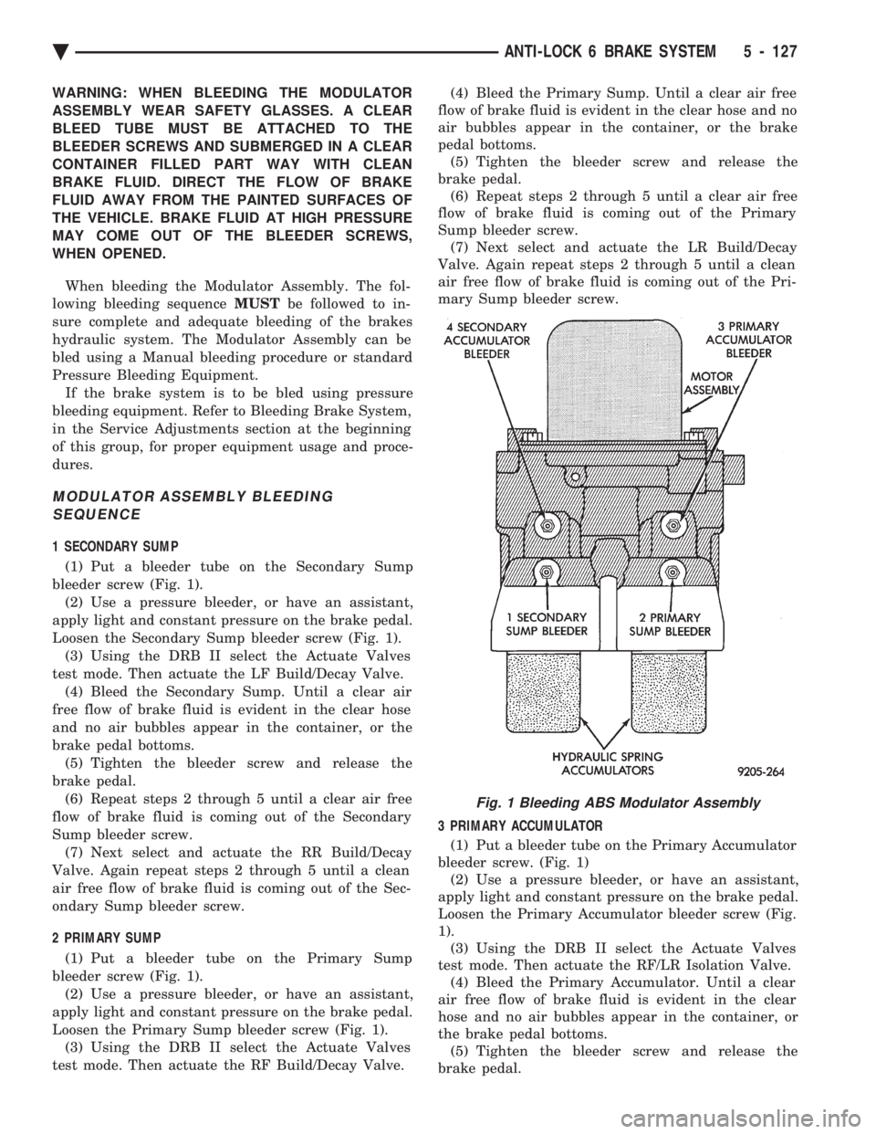
1 SECONDARY SUMP
(1) Put a bleeder tube on the Secondary Sump
bleeder screw (Fig. 1). (2) Use a pressure bleeder, or have an assistant,
apply light and constant pressure on the brake pedal.
Loosen the Secondary Sump bleeder screw (Fig. 1). (3) Using the DRB II select the Actuate Valves
test mode. Then actuate the LF Build/Decay Valve. (4) Bleed the Secondary Sump. Until a clear air
free flow of brake fluid is evident in the clear hose
and no air bubbles appear in the container, or the
brake pedal bottoms. (5) Tighten the bleeder screw and release the
brake pedal. (6) Repeat steps 2 through 5 until a clear air free
flow of brake fluid is coming out of the Secondary
Sump bleeder screw. (7) Next select and actuate the RR Build/Decay
Valve. Again repeat steps 2 through 5 until a clean
air free flow of brake fluid is coming out of the Sec-
ondary Sump bleeder screw.
2 PRIMARY SUMP
(1) Put a bleeder tube on the Primary Sump
bleeder screw (Fig. 1). (2) Use a pressure bleeder, or have an assistant,
apply light and constant pressure on the brake pedal.
Loosen the Primary Sump bleeder screw (Fig. 1). (3) Using the DRB II select the Actuate Valves
test mode. Then actuate the RF Build/Decay Valve. (4) Bleed the Primary Sump. Until a clear air free
flow of brake fluid is evident in the clear hose and no
air bubbles appear in the container, or the brake
pedal bottoms. (5) Tighten the bleeder screw and release the
brake pedal. (6) Repeat steps 2 through 5 until a clear air free
flow of brake fluid is coming out of the Primary
Sump bleeder screw. (7) Next select and actuate the LR Build/Decay
Valve. Again repeat steps 2 through 5 until a clean
air free flow of brake fluid is coming out of the Pri-
mary Sump bleeder screw.
3 PRIMARY ACCUMULATOR
(1) Put a bleeder tube on the Primary Accumulator
bleeder screw. (Fig. 1) (2) Use a pressure bleeder, or have an assistant,
apply light and constant pressure on the brake pedal.
Loosen the Primary Accumulator bleeder screw (Fig.
1). (3) Using the DRB II select the Actuate Valves
test mode. Then actuate the RF/LR Isolation Valve. (4) Bleed the Primary Accumulator. Until a clear
air free flow of brake fluid is evident in the clear
hose and no air bubbles appear in the container, or
the brake pedal bottoms. (5) Tighten the bleeder screw and release the
brake pedal.
Fig. 1 Bleeding ABS Modulator Assembly
Ä ANTI-LOCK 6 BRAKE SYSTEM 5 - 127
Page 287 of 2438
BRAKES
CONTENTS
page page
BENDIX ANTILOCK 4 BRAKE SYSTEM ...... 12
GENERAL INFORMATION .................. 1 HYDRAULIC SYSTEM CONTROL VALVES . . . 10
SERVICE ADJUSTMENTS
.................. 3
GENERAL INFORMATION
Throughout this group, references may be made to
a particular vehicle by letter or number designation.
A chart showing the break down of these designa-
tions is included in the Introduction Section at the
front of this service manual. Standard brake equipment consists of:
² Double pin floating caliper disc front brakes.
² Rear automatic adjusting drum brakes.
² Differential valve with a brake warning switch.
² Master cylinder.
² Vacuum power booster.
² Double pin floating caliper rear disc brakes are
available on some models. The Bendix Antilock 4 Brake System, uses the fol-
lowing standard brake system components. Master
cylinder, power booster, caliper assemblies, braking
discs, pedal assembly, brake lines and hoses. The
unique parts of the Bendix Antilock 4 Brake System
consists of the following components, modulator as-
sembly, unique proportioning valves, unique junction
block, wheel speed sensors, tone wheels, and elec-
tronic control unit. These components will be de-
scribed in detail in the Bendix Antilock 4 Brake
System section in this service manual supplement. The hydraulic system, (Fig. 1) on the Bendix Anti-
lock 4 brake system is diagonally split. Diagonally
split hydraulic brake systems, have the left front and
right rear brakes on one hydraulic system and the
right front and left rear on the other. A diagonally
split hydraulic brake system, will maintain half of
the vehicles braking capability if there is a failure in
either half of the hydraulic system. The Bendix Antilock 4 Brake System uses two
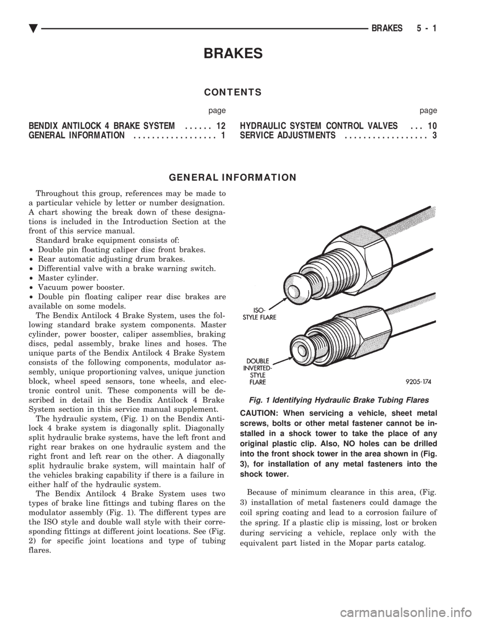
types of brake line fittings and tubing flares on the
modulator assembly (Fig. 1). The different types are
the ISO style and double wall style with their corre-
sponding fittings at different joint locations. See (Fig.
2) for specific joint locations and type of tubing
flares. CAUTION: When servicing a vehicle, sheet metal
screws, bolts or other metal fastener cannot be in-
stalled in a shock tower to take the place of any
original plastic clip. Also, NO holes can be drilled
into the front shock tower in the area shown in (Fig.
3), for installation of any metal fasteners into the
shock tower.
Because of minimum clearance in this area, (Fig.
3) installation of metal fasteners could damage the
coil spring coating and lead to a corrosion failure of
the spring. If a plastic clip is missing, lost or broken
during servicing a vehicle, replace only with the
equivalent part listed in the Mopar parts catalog.
Fig. 1 Identifying Hydraulic Brake Tubing Flares
Ä BRAKES 5 - 1
Page 288 of 2438
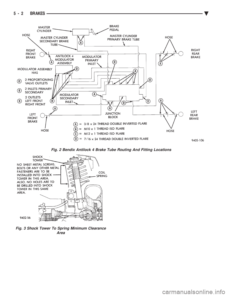
Fig. 2 Bendix Antilock 4 Brake Tube Routing And Fitting Locations
Fig. 3 Shock Tower To Spring Minimum Clearance Area
5 - 2 BRAKES Ä
Page 289 of 2438
SERVICE ADJUSTMENTS INDEX
page page
Bleeding Bendix Antilock 4 Brake System ....... 3
Master Cylinder Fluid Level .................. 3 Testing for Fluid Contamination
............... 4
MASTER CYLINDER FLUID LEVEL
Check master cylinder reservoir brake fluid level a
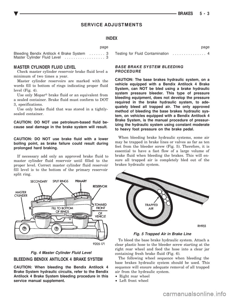
minimum of two times a year. Master cylinder reservoirs are marked with the
words fill to bottom of rings indicating proper fluid
level (Fig. 4). Use only Mopar tbrake fluid or an equivalent from
a sealed container. Brake fluid must conform to DOT
3, specifications. Use only brake fluid that was stored in a tightly-
sealed container.
CAUTION: DO NOT use petroleum-based fluid be-
cause seal damage in the brake system will result.
CAUTION: DO NOT use brake fluid with a lower
boiling point, as brake failure could result during
prolonged hard braking.
If necessary add only an approved brake fluid to
master cylinder fluid reservoir until filled to the
proper level. Correct master cylinder fluid reservoir
fill level is to the bottom of the primary reservoir
split ring.
BLEEDING BENDIX ANTILOCK 4 BRAKE SYSTEM
CAUTION: When bleeding the Bendix Antilock 4
Brake System hydraulic circuits, refer to the Bendix
Antilock 4 Brake System bleeding procedure in this
service manual supplement.
BASE BRAKE SYSTEM BLEEDING PROCEDURE
CAUTION: The base brakes hydraulic system, on a
vehicle equipped with a Bendix Antilock 4 Brake
System, can NOT be bled using a brake hydraulic
system pressure bleeder. This type of pressure
bleeding equipment, does not develop the pressure
required in the brake hydraulic system, to ade-
quately bleed all trapped air. The only approved
method of bleeding the base brakes hydraulic sys-
tem, on vehicles equipped with a Bendix Antilock 4
Brake System, is the manual procedure of pressur-
izing the hydraulic system using constant moderate
to heavy foot pressure on the brake pedal.
When bleeding brake hydraulic systems, some air
may be trapped in brake lines or valves as far as ten
feet from the bleeder screw (Fig. 5). Therefore, it is
essential to have a fast flow of a large volume of
brake fluid when bleeding the brakes. This will en-
sure all trapped air is completely bled out of the
brakes hydraulic system.
To bleed the base brake hydraulic system. Attach a
clear plastic hose to the bleeder screw starting at the
right rear wheel and feed the hose into a clear jar
containing fresh brake fluid (Fig. 6). The following wheel sequence when bleeding the
base brakes hydraulic system should be used. This
sequence will ensure adequate removal of all trapped
air from the hydraulic system.
² Right rear wheel
² Left front wheel
Fig. 4 Master Cylinder Fluid Level
Fig. 5 Trapped Air in Brake Line
Ä BRAKES 5 - 3
Page 290 of 2438
² Left rear wheel
² Right front wheel
(1) Pump brake pedal three or four times, then
hold a constant moderate to heavy foot pressure on
the brake pedal.
CAUTION: Just cracking the bleeder screw often re-
stricts fluid flow, and a slow, weak fluid discharge
will NOT get all the air out.
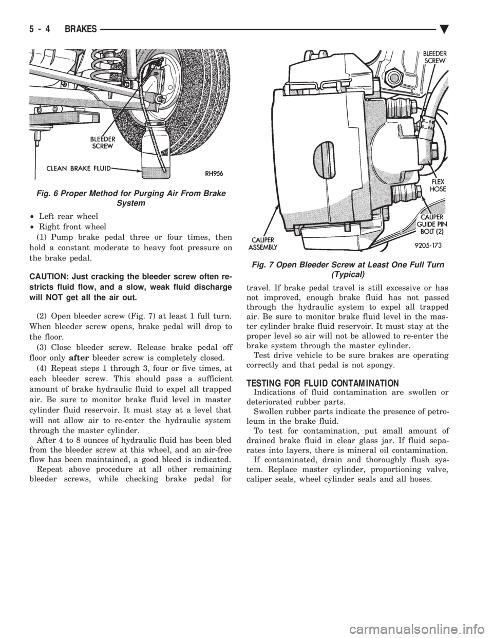
(2) Open bleeder screw (Fig. 7) at least 1 full turn.
When bleeder screw opens, brake pedal will drop to
the floor. (3) Close bleeder screw. Release brake pedal off
floor only afterbleeder screw is completely closed.
(4) Repeat steps 1 through 3, four or five times, at
each bleeder screw. This should pass a sufficient
amount of brake hydraulic fluid to expel all trapped
air. Be sure to monitor brake fluid level in master
cylinder fluid reservoir. It must stay at a level that
will not allow air to re-enter the hydraulic system
through the master cylinder. After 4 to 8 ounces of hydraulic fluid has been bled
from the bleeder screw at this wheel, and an air-free
flow has been maintained, a good bleed is indicated. Repeat above procedure at all other remaining
bleeder screws, while checking brake pedal for travel. If brake pedal travel is still excessive or has
not improved, enough brake fluid has not passed
through the hydraulic system to expel all trapped
air. Be sure to monitor brake fluid level in the mas-
ter cylinder brake fluid reservoir. It must stay at the
proper level so air will not be allowed to re-enter the
brake system through the master cylinder. Test drive vehicle to be sure brakes are operating
correctly and that pedal is not spongy.
TESTING FOR FLUID CONTAMINATION
Indications of fluid contamination are swollen or
deteriorated rubber parts. Swollen rubber parts indicate the presence of petro-
leum in the brake fluid. To test for contamination, put small amount of
drained brake fluid in clear glass jar. If fluid sepa-
rates into layers, there is mineral oil contamination. If contaminated, drain and thoroughly flush sys-
tem. Replace master cylinder, proportioning valve,
caliper seals, wheel cylinder seals and all hoses.
Fig. 6 Proper Method for Purging Air From Brake System
Fig. 7 Open Bleeder Screw at Least One Full Turn(Typical)
5 - 4 BRAKES Ä
Page 291 of 2438

BASIC DIAGNOSIS GUIDE
Ä BRAKES 5 - 5
Page 292 of 2438

BRAKE SYSTEM DIAGNOSTICS
5 - 6 BRAKES Ä