brake light CHEVROLET DYNASTY 1993 User Guide
[x] Cancel search | Manufacturer: CHEVROLET, Model Year: 1993, Model line: DYNASTY, Model: CHEVROLET DYNASTY 1993Pages: 2438, PDF Size: 74.98 MB
Page 173 of 2438
WHEEL CYLINDERS INDEX
page page
General Information ....................... 23
Installing Wheel Cylinders .................. 24 Service Procedures
....................... 23
GENERAL INFORMATION
The piston boots are of the push-on type and pre-
vent moisture from entering the wheel cylinder. To perform service operations or inspections of the
rear wheel brake cylinders. It will be necessary to re-
move the cylinders from the support plate and disas-
semble on the bench.
CAUTION: Wheel cylinders with cup expanders
must have cup expanders after any service proce-
dures (reconditioning or replacement).
SERVICE PROCEDURES
REMOVING WHEEL CYLINDERS FROM BRAKE SUPPORT PLATES
With brake drums removed, inspect the wheel cyl-
inder boots for evidence of a brake fluid leak. Then
block the brake pedal in the stroke position, and vi-
sually check the boots for cuts, tears, or heat cracks.
If any of these conditions exist, the wheel cylinders
should be completely cleaned, inspected and new
parts installed. (A slight amount of fluid on the boot
may not be a leak, but may be preservative fluid
used at assembly.) (1) In case of a leak, remove brake shoes, (replace
if soaked with grease or brake fluid.) (2) Thoroughly clean area of wheel cylinder, where
hydraulic brake line connects to wheel cylinder. Dis-
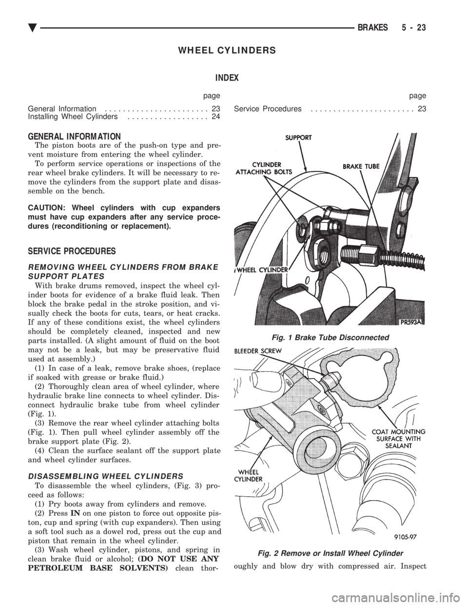
connect hydraulic brake tube from wheel cylinder
(Fig. 1). (3) Remove the rear wheel cylinder attaching bolts
(Fig. 1). Then pull wheel cylinder assembly off the
brake support plate (Fig. 2). (4) Clean the surface sealant off the support plate
and wheel cylinder surfaces.
DISASSEMBLING WHEEL CYLINDERS
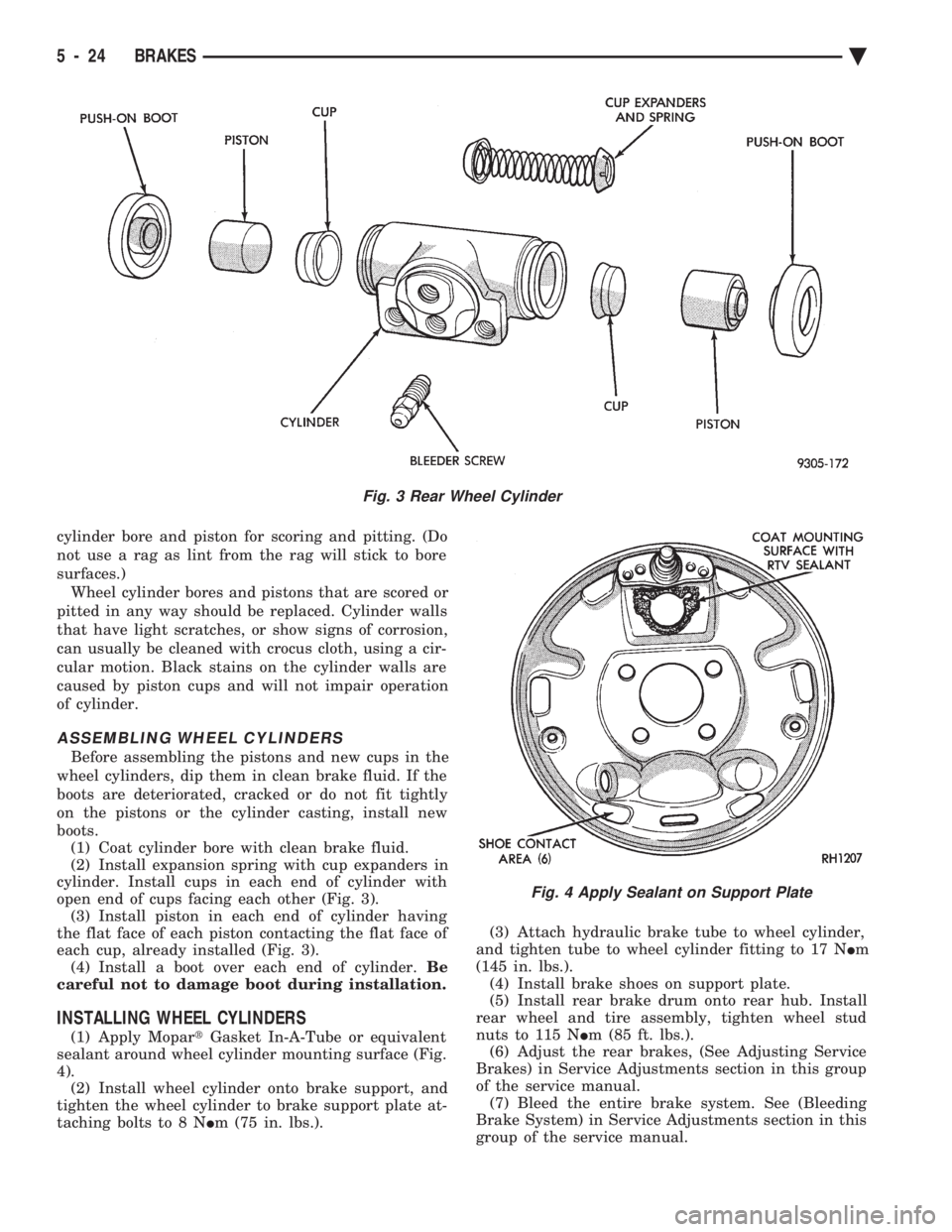
To disassemble the wheel cylinders, (Fig. 3) pro-
ceed as follows: (1) Pry boots away from cylinders and remove.
(2) Press INon one piston to force out opposite pis-
ton, cup and spring (with cup expanders). Then using
a soft tool such as a dowel rod, press out the cup and
piston that remain in the wheel cylinder. (3) Wash wheel cylinder, pistons, and spring in
clean brake fluid or alcohol; (DO NOT USE ANY
PETROLEUM BASE SOLVENTS) clean thor- oughly and blow dry with compressed air. Inspect
Fig. 1 Brake Tube Disconnected
Fig. 2 Remove or Install Wheel Cylinder
Ä
BRAKES 5 - 23
Page 174 of 2438
cylinder bore and piston for scoring and pitting. (Do
not use a rag as lint from the rag will stick to bore
surfaces.) Wheel cylinder bores and pistons that are scored or
pitted in any way should be replaced. Cylinder walls
that have light scratches, or show signs of corrosion,
can usually be cleaned with crocus cloth, using a cir-
cular motion. Black stains on the cylinder walls are
caused by piston cups and will not impair operation
of cylinder.
ASSEMBLING WHEEL CYLINDERS
Before assembling the pistons and new cups in the
wheel cylinders, dip them in clean brake fluid. If the
boots are deteriorated, cracked or do not fit tightly
on the pistons or the cylinder casting, install new
boots. (1) Coat cylinder bore with clean brake fluid.
(2) Install expansion spring with cup expanders in
cylinder. Install cups in each end of cylinder with
open end of cups facing each other (Fig. 3). (3) Install piston in each end of cylinder having
the flat face of each piston contacting the flat face of
each cup, already installed (Fig. 3). (4) Install a boot over each end of cylinder. Be
careful not to damage boot during installation.
INSTALLING WHEEL CYLINDERS
(1) Apply Mopar tGasket In-A-Tube or equivalent
sealant around wheel cylinder mounting surface (Fig.
4). (2) Install wheel cylinder onto brake support, and
tighten the wheel cylinder to brake support plate at-
taching bolts to 8 N Im (75 in. lbs.). (3) Attach hydraulic brake tube to wheel cylinder,
and tighten tube to wheel cylinder fitting to 17 N Im
(145 in. lbs.). (4) Install brake shoes on support plate.
(5) Install rear brake drum onto rear hub. Install
rear wheel and tire assembly, tighten wheel stud
nuts to 115 N Im (85 ft. lbs.).
(6) Adjust the rear brakes, (See Adjusting Service
Brakes) in Service Adjustments section in this group
of the service manual. (7) Bleed the entire brake system. See (Bleeding
Brake System) in Service Adjustments section in this
group of the service manual.
Fig. 3 Rear Wheel Cylinder
Fig. 4 Apply Sealant on Support Plate
5 - 24 BRAKES Ä
Page 176 of 2438
HYDRAULIC SYSTEM CONTROL VALVES INDEX
page page
ABS Brake Proportioning Valve Operation ...... 27
General Information ....................... 26
Hydraulic System Service Procedures ......... 27 Non-ABS Proportioning Unit Operation
........ 26
Pressure Differential Warning Light Switch ...... 26
Testing ABS Proportioning Valves ............ 29
GENERAL INFORMATION
Most models not equipped with an Anti-Lock brak-
ing system have a combination hydraulic system con-
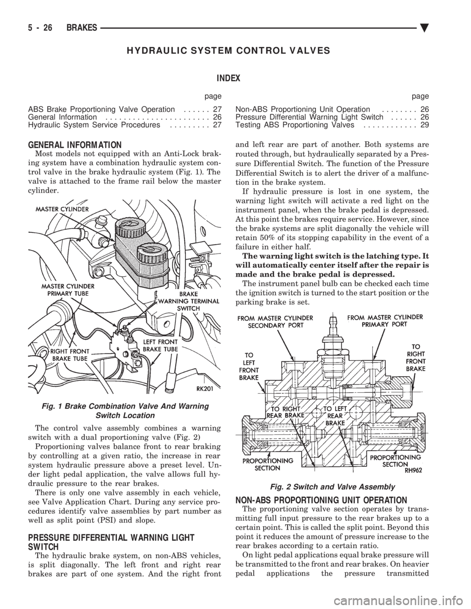
trol valve in the brake hydraulic system (Fig. 1). The
valve is attached to the frame rail below the master
cylinder.
The control valve assembly combines a warning
switch with a dual proportioning valve (Fig. 2) Proportioning valves balance front to rear braking
by controlling at a given ratio, the increase in rear
system hydraulic pressure above a preset level. Un-
der light pedal application, the valve allows full hy-
draulic pressure to the rear brakes. There is only one valve assembly in each vehicle,
see Valve Application Chart. During any service pro-
cedures identify valve assemblies by part number as
well as split point (PSI) and slope.
PRESSURE DIFFERENTIAL WARNING LIGHT
SWITCH
The hydraulic brake system, on non-ABS vehicles,
is split diagonally. The left front and right rear
brakes are part of one system. And the right front and left rear are part of another. Both systems are
routed through, but hydraulically separated by a Pres-
sure Differential Switch. The function of the Pressure
Differential Switch is to alert the driver of a malfunc-
tion in the brake system. If hydraulic pressure is lost in one system, the
warning light switch will activate a red light on the
instrument panel, when the brake pedal is depressed.
At this point the brakes require service. However, since
the brake systems are split diagonally the vehicle will
retain 50% of its stopping capability in the event of a
failure in either half. The warning light switch is the latching type. It
will automatically center itself after the repair is
made and the brake pedal is depressed. The instrument panel bulb can be checked each time
the ignition switch is turned to the start position or the
parking brake is set.
NON-ABS PROPORTIONING UNIT OPERATION
The proportioning valve section operates by trans-
mitting full input pressure to the rear brakes up to a
certain point. This is called the split point. Beyond this
point it reduces the amount of pressure increase to the
rear brakes according to a certain ratio. On light pedal applications equal brake pressure will
be transmitted to the front and rear brakes. On heavier
pedal applications the pressure transmitted
Fig. 1 Brake Combination Valve And Warning Switch Location
Fig. 2 Switch and Valve Assembly
5 - 26 BRAKES Ä
Page 177 of 2438
to the rear will be lower than the front brakes. This will
prevent premature rear wheel lock-up and skid. If
hydraulic pressure is lost in one half of the diagonally
split system, the operation of the proportioning valve
in the remaining half is not effected.
ABS BRAKE PROPORTIONING VALVE OPERATION
On vehicles using the ABS braking system, screw in
proportioning valves are used in place of the conven-
tional differential pressure/proportioning valve. Each rear brake circuit has its own screw-in propor-
tioning valve which is attached to the rear brake outlet
ports of the hydraulic assembly. These valves limit
brake pressure to the rear brakes after a certain
pressure is reached. This improves front to rear brake
balance during normal braking.
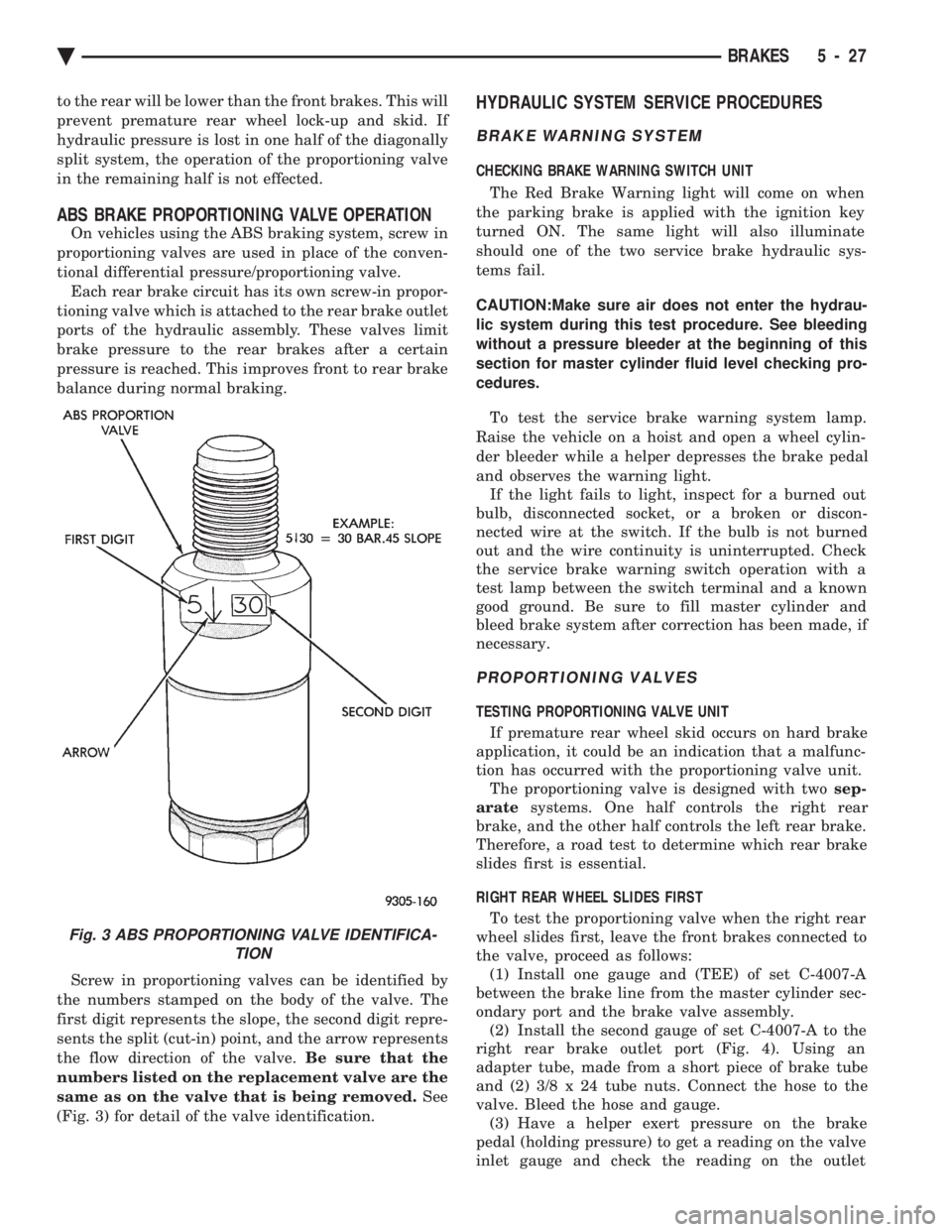
Screw in proportioning valves can be identified by
the numbers stamped on the body of the valve. The
first digit represents the slope, the second digit repre-
sents the split (cut-in) point, and the arrow represents
the flow direction of the valve. Be sure that the
numbers listed on the replacement valve are the
same as on the valve that is being removed. See
(Fig. 3) for detail of the valve identification.
HYDRAULIC SYSTEM SERVICE PROCEDURES
BRAKE WARNING SYSTEM
CHECKING BRAKE WARNING SWITCH UNIT
The Red Brake Warning light will come on when
the parking brake is applied with the ignition key
turned ON. The same light will also illuminate
should one of the two service brake hydraulic sys-
tems fail.
CAUTION:Make sure air does not enter the hydrau-
lic system during this test procedure. See bleeding
without a pressure bleeder at the beginning of this
section for master cylinder fluid level checking pro-
cedures.
To test the service brake warning system lamp.
Raise the vehicle on a hoist and open a wheel cylin-
der bleeder while a helper depresses the brake pedal
and observes the warning light. If the light fails to light, inspect for a burned out
bulb, disconnected socket, or a broken or discon-
nected wire at the switch. If the bulb is not burned
out and the wire continuity is uninterrupted. Check
the service brake warning switch operation with a
test lamp between the switch terminal and a known
good ground. Be sure to fill master cylinder and
bleed brake system after correction has been made, if
necessary.
PROPORTIONING VALVES
TESTING PROPORTIONING VALVE UNIT
If premature rear wheel skid occurs on hard brake
application, it could be an indication that a malfunc-
tion has occurred with the proportioning valve unit. The proportioning valve is designed with two sep-
arate systems. One half controls the right rear
brake, and the other half controls the left rear brake.
Therefore, a road test to determine which rear brake
slides first is essential.
RIGHT REAR WHEEL SLIDES FIRST To test the proportioning valve when the right rear
wheel slides first, leave the front brakes connected to
the valve, proceed as follows: (1) Install one gauge and (TEE) of set C-4007-A
between the brake line from the master cylinder sec-
ondary port and the brake valve assembly. (2) Install the second gauge of set C-4007-A to the
right rear brake outlet port (Fig. 4). Using an
adapter tube, made from a short piece of brake tube
and (2) 3/8 x 24 tube nuts. Connect the hose to the
valve. Bleed the hose and gauge. (3) Have a helper exert pressure on the brake
pedal (holding pressure) to get a reading on the valve
inlet gauge and check the reading on the outlet
Fig. 3 ABS PROPORTIONING VALVE IDENTIFICA- TION
Ä BRAKES 5 - 27
Page 191 of 2438
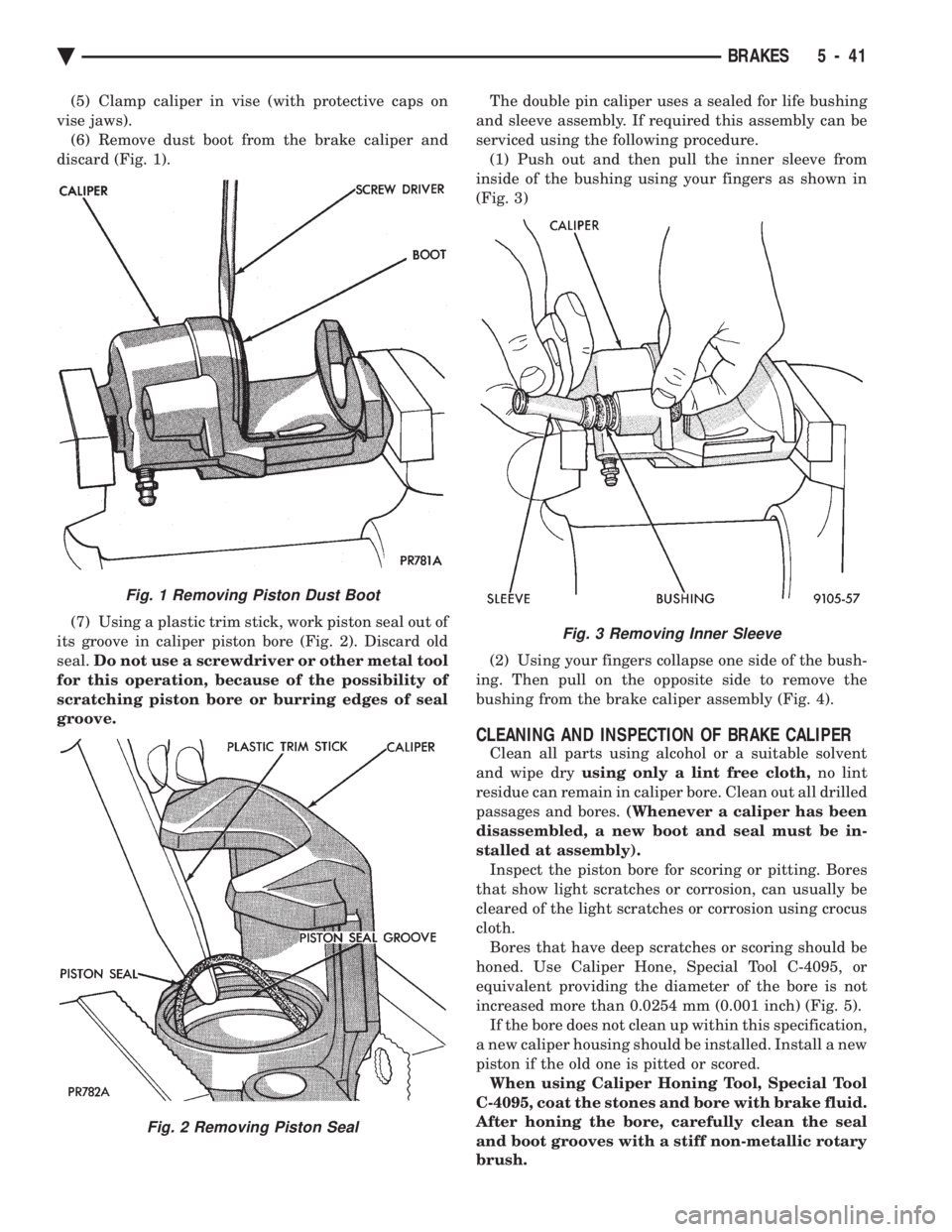
(5) Clamp caliper in vise (with protective caps on
vise jaws). (6) Remove dust boot from the brake caliper and
discard (Fig. 1).
(7) Using a plastic trim stick, work piston seal out of
its groove in caliper piston bore (Fig. 2). Discard old
seal. Do not use a screwdriver or other metal tool
for this operation, because of the possibility of
scratching piston bore or burring edges of seal
groove. The double pin caliper uses a sealed for life bushing
and sleeve assembly. If required this assembly can be
serviced using the following procedure. (1) Push out and then pull the inner sleeve from
inside of the bushing using your fingers as shown in
(Fig. 3)
(2) Using your fingers collapse one side of the bush-
ing. Then pull on the opposite side to remove the
bushing from the brake caliper assembly (Fig. 4).
CLEANING AND INSPECTION OF BRAKE CALIPER
Clean all parts using alcohol or a suitable solvent
and wipe dry using only a lint free cloth, no lint
residue can remain in caliper bore. Clean out all drilled
passages and bores. (Whenever a caliper has been
disassembled, a new boot and seal must be in-
stalled at assembly). Inspect the piston bore for scoring or pitting. Bores
that show light scratches or corrosion, can usually be
cleared of the light scratches or corrosion using crocus
cloth. Bores that have deep scratches or scoring should be
honed. Use Caliper Hone, Special Tool C-4095, or
equivalent providing the diameter of the bore is not
increased more than 0.0254 mm (0.001 inch) (Fig. 5). If the bore does not clean up within this specification,
a new caliper housing should be installed. Install a new
piston if the old one is pitted or scored. When using Caliper Honing Tool, Special Tool
C-4095, coat the stones and bore with brake fluid.
After honing the bore, carefully clean the seal
and boot grooves with a stiff non-metallic rotary
brush.
Fig. 1 Removing Piston Dust Boot
Fig. 2 Removing Piston Seal
Fig. 3 Removing Inner Sleeve
Ä BRAKES 5 - 41
Page 199 of 2438
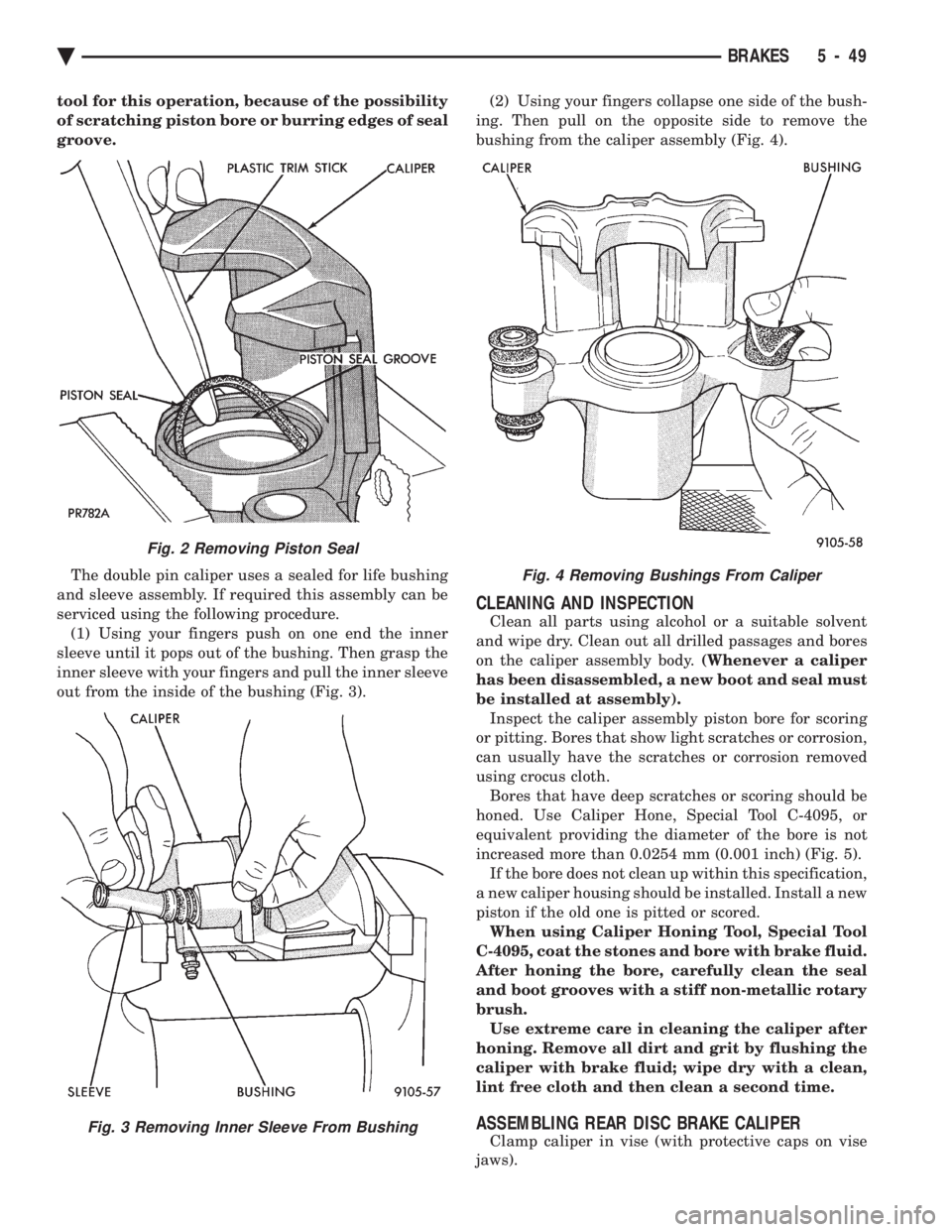
tool for this operation, because of the possibility
of scratching piston bore or burring edges of seal
groove. The double pin caliper uses a sealed for life bushing
and sleeve assembly. If required this assembly can be
serviced using the following procedure. (1) Using your fingers push on one end the inner
sleeve until it pops out of the bushing. Then grasp the
inner sleeve with your fingers and pull the inner sleeve
out from the inside of the bushing (Fig. 3). (2) Using your fingers collapse one side of the bush-
ing. Then pull on the opposite side to remove the
bushing from the caliper assembly (Fig. 4).
CLEANING AND INSPECTION
Clean all parts using alcohol or a suitable solvent
and wipe dry. Clean out all drilled passages and bores
on the caliper assembly body. (Whenever a caliper
has been disassembled, a new boot and seal must
be installed at assembly). Inspect the caliper assembly piston bore for scoring
or pitting. Bores that show light scratches or corrosion,
can usually have the scratches or corrosion removed
using crocus cloth. Bores that have deep scratches or scoring should be
honed. Use Caliper Hone, Special Tool C-4095, or
equivalent providing the diameter of the bore is not
increased more than 0.0254 mm (0.001 inch) (Fig. 5). If the bore does not clean up within this specification,
a new caliper housing should be installed. Install a new
piston if the old one is pitted or scored. When using Caliper Honing Tool, Special Tool
C-4095, coat the stones and bore with brake fluid.
After honing the bore, carefully clean the seal
and boot grooves with a stiff non-metallic rotary
brush. Use extreme care in cleaning the caliper after
honing. Remove all dirt and grit by flushing the
caliper with brake fluid; wipe dry with a clean,
lint free cloth and then clean a second time.
ASSEMBLING REAR DISC BRAKE CALIPER
Clamp caliper in vise (with protective caps on vise
jaws).
Fig. 2 Removing Piston Seal
Fig. 3 Removing Inner Sleeve From Bushing
Fig. 4 Removing Bushings From Caliper
Ä BRAKES 5 - 49
Page 204 of 2438
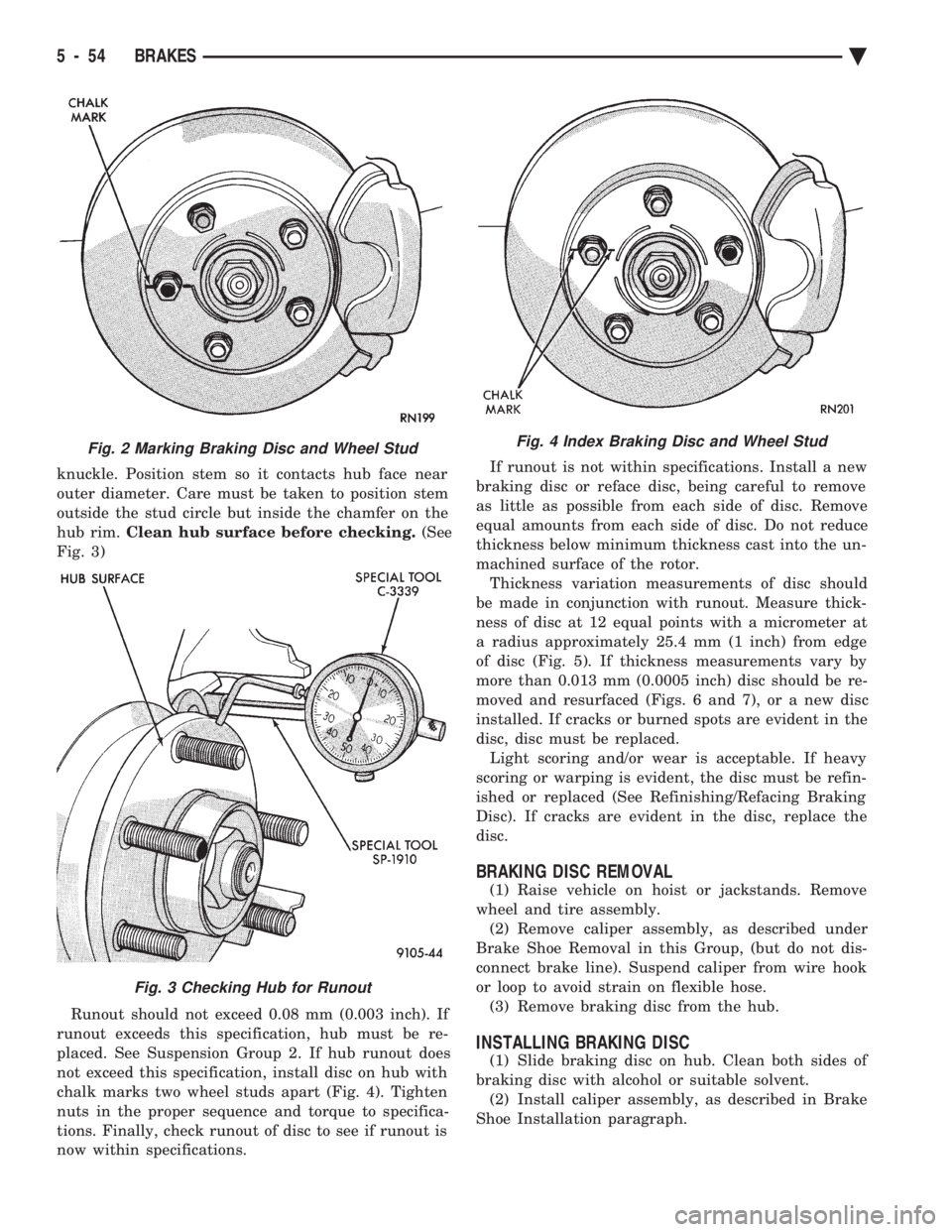
knuckle. Position stem so it contacts hub face near
outer diameter. Care must be taken to position stem
outside the stud circle but inside the chamfer on the
hub rim. Clean hub surface before checking. (See
Fig. 3)
Runout should not exceed 0.08 mm (0.003 inch). If
runout exceeds this specification, hub must be re-
placed. See Suspension Group 2. If hub runout does
not exceed this specification, install disc on hub with
chalk marks two wheel studs apart (Fig. 4). Tighten
nuts in the proper sequence and torque to specifica-
tions. Finally, check runout of disc to see if runout is
now within specifications. If runout is not within specifications. Install a new
braking disc or reface disc, being careful to remove
as little as possible from each side of disc. Remove
equal amounts from each side of disc. Do not reduce
thickness below minimum thickness cast into the un-
machined surface of the rotor. Thickness variation measurements of disc should
be made in conjunction with runout. Measure thick-
ness of disc at 12 equal points with a micrometer at
a radius approximately 25.4 mm (1 inch) from edge
of disc (Fig. 5). If thickness measurements vary by
more than 0.013 mm (0.0005 inch) disc should be re-
moved and resurfaced (Figs. 6 and 7), or a new disc
installed. If cracks or burned spots are evident in the
disc, disc must be replaced. Light scoring and/or wear is acceptable. If heavy
scoring or warping is evident, the disc must be refin-
ished or replaced (See Refinishing/Refacing Braking
Disc). If cracks are evident in the disc, replace the
disc.
BRAKING DISC REMOVAL
(1) Raise vehicle on hoist or jackstands. Remove
wheel and tire assembly. (2) Remove caliper assembly, as described under
Brake Shoe Removal in this Group, (but do not dis-
connect brake line). Suspend caliper from wire hook
or loop to avoid strain on flexible hose. (3) Remove braking disc from the hub.
INSTALLING BRAKING DISC
(1) Slide braking disc on hub. Clean both sides of
braking disc with alcohol or suitable solvent. (2) Install caliper assembly, as described in Brake
Shoe Installation paragraph.
Fig. 2 Marking Braking Disc and Wheel Stud
Fig. 3 Checking Hub for Runout
Fig. 4 Index Braking Disc and Wheel Stud
5 - 54 BRAKES Ä
Page 207 of 2438
PARKING BRAKES INDEX
page page
Adjust Parking Brake (AG & AJ Body) ........ 61
General Information ....................... 57
Installing Parking Brake Front Cable (AA, AC, AP AY Body) ............................. 62
Installing Parking Brake Shoes .............. 64
Parking Brake Hand Lever Assembly Removal and Installation ............................ 63
Rear Parking Brake Cable Installation ......... 62 Rear Parking Brake Cable Removal (AA, AC, AP,
AY Body) ............................. 61
Removal and Installation Parking Brake Shoes . . 63
Removing Parking Brake Front Cable (AA, AC, AP, AY Body) ............................. 62
Self Adjusting Procedures (AG & AJ Body) ..... 61
Service Procedures ....................... 57
GENERAL INFORMATION
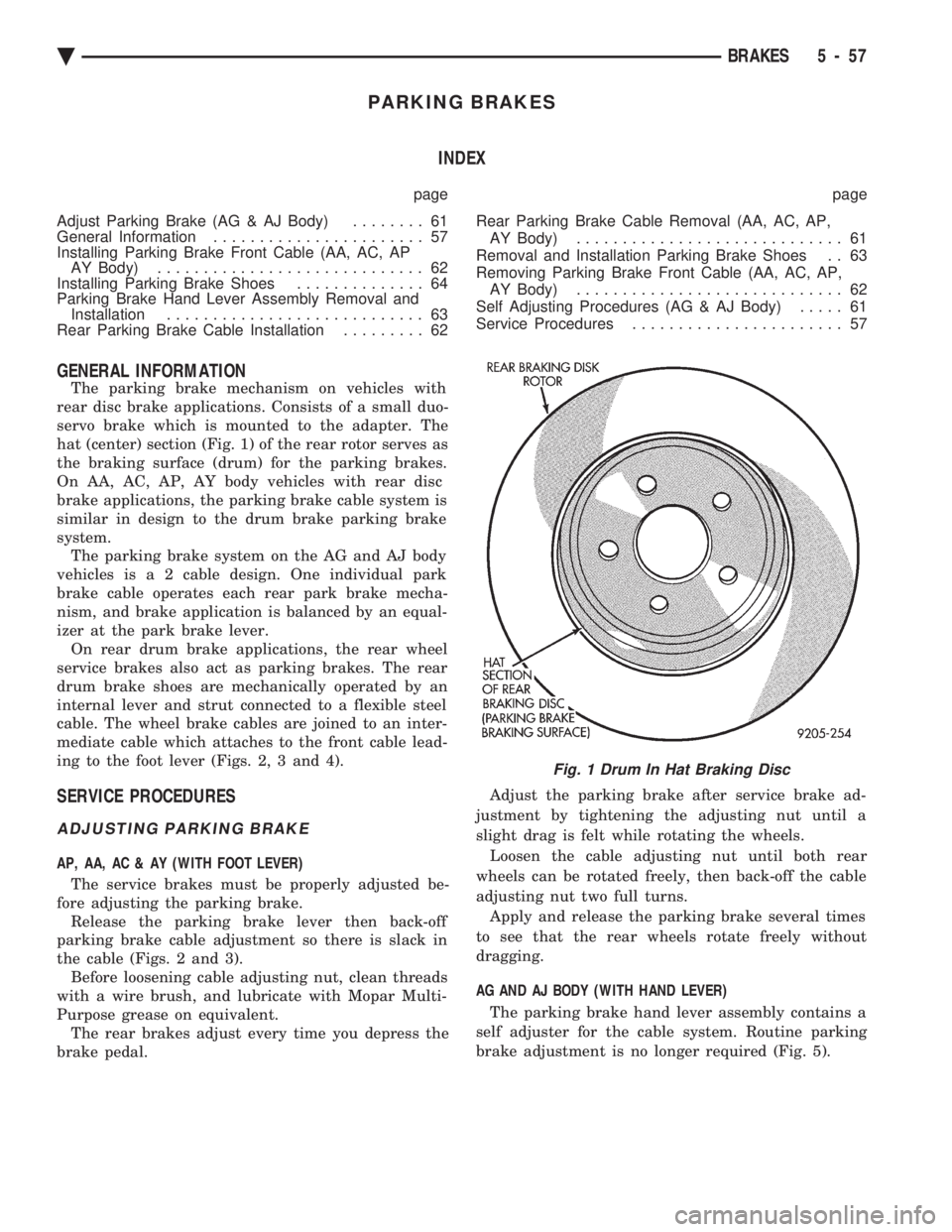
The parking brake mechanism on vehicles with
rear disc brake applications. Consists of a small duo-
servo brake which is mounted to the adapter. The
hat (center) section (Fig. 1) of the rear rotor serves as
the braking surface (drum) for the parking brakes.
On AA, AC, AP, AY body vehicles with rear disc
brake applications, the parking brake cable system is
similar in design to the drum brake parking brake
system. The parking brake system on the AG and AJ body
vehicles i s a 2 cable design. One individual park
brake cable operates each rear park brake mecha-
nism, and brake application is balanced by an equal-
izer at the park brake lever. On rear drum brake applications, the rear wheel
service brakes also act as parking brakes. The rear
drum brake shoes are mechanically operated by an
internal lever and strut connected to a flexible steel
cable. The wheel brake cables are joined to an inter-
mediate cable which attaches to the front cable lead-
ing to the foot lever (Figs. 2, 3 and 4).
SERVICE PROCEDURES
ADJUSTING PARKING BRAKE
AP, AA, AC & AY (WITH FOOT LEVER)
The service brakes must be properly adjusted be-
fore adjusting the parking brake. Release the parking brake lever then back-off
parking brake cable adjustment so there is slack in
the cable (Figs. 2 and 3). Before loosening cable adjusting nut, clean threads
with a wire brush, and lubricate with Mopar Multi-
Purpose grease on equivalent. The rear brakes adjust every time you depress the
brake pedal. Adjust the parking brake after service brake ad-
justment by tightening the adjusting nut until a
slight drag is felt while rotating the wheels. Loosen the cable adjusting nut until both rear
wheels can be rotated freely, then back-off the cable
adjusting nut two full turns. Apply and release the parking brake several times
to see that the rear wheels rotate freely without
dragging.
AG AND AJ BODY (WITH HAND LEVER) The parking brake hand lever assembly contains a
self adjuster for the cable system. Routine parking
brake adjustment is no longer required (Fig. 5).
Fig. 1 Drum In Hat Braking Disc
Ä BRAKES 5 - 57
Page 211 of 2438
WARNING: THE SELF ADJUSTING FEATURE OF THIS
PARKING BRAKE LEVER ASSEMBLY CONTAINS A
CLOCK SPRING LOADED TO APPROXIMATELY 30
POUNDS. CARE MUST BE TAKEN TO PREVENT EX-
CESSIVE JARRING OF THE ASSEMBLY. DO NOT
RELEASE THE SELF ADJUSTER LOCKOUT DEVICE
BEFORE INSTALLING CABLES INTO THE EQUAL-
IZER. KEEP HANDS OUT OF SELF ADJUSTER SEC-
TOR AND PAWL AREA. FAILURE TO OBSERVE CAU-
TION IN HANDLING THIS MECHANISM COULD LEAD
TO SERIOUS INJURY.
When repairs to the hand lever assembly or cable
system are required the self adjuster must be reloaded
and locked out.
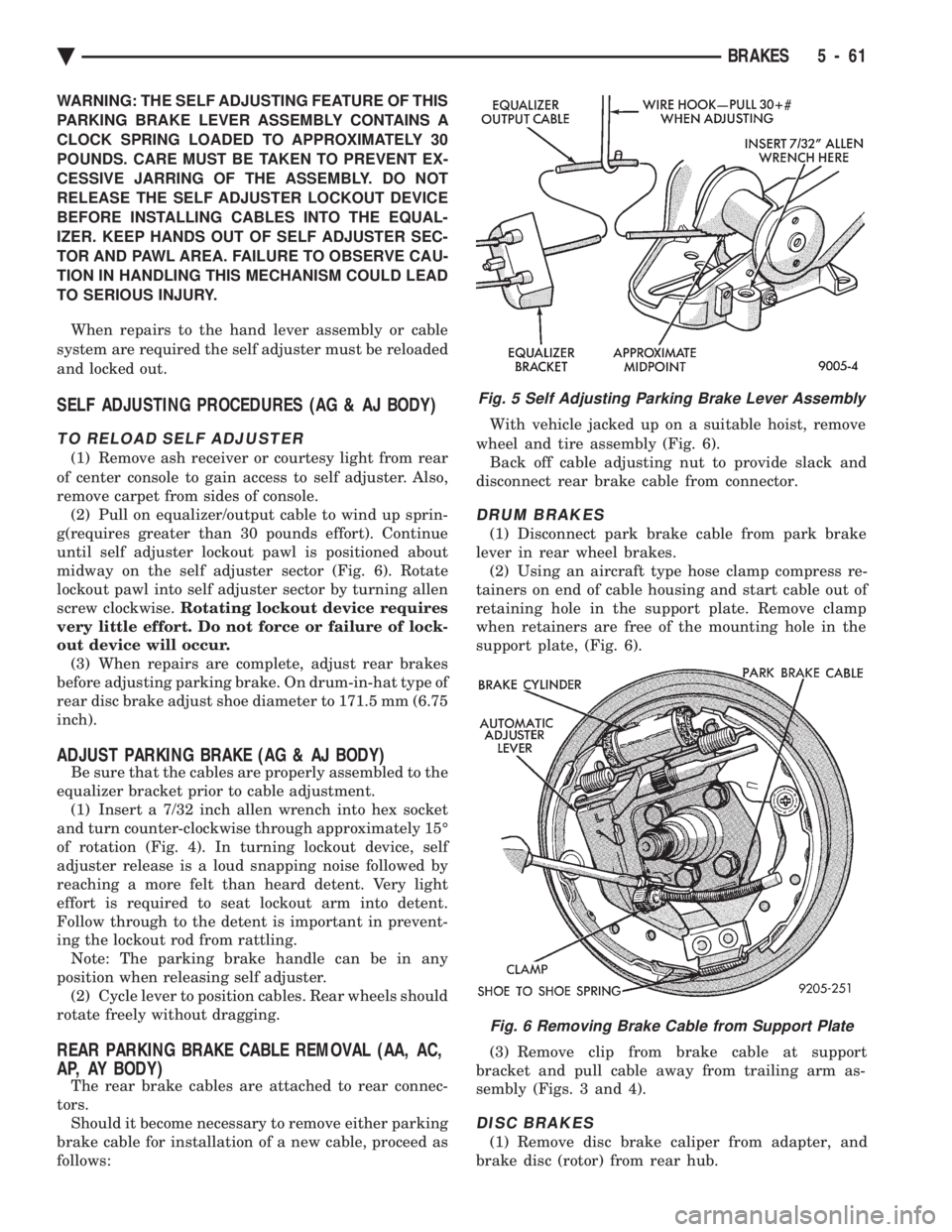
SELF ADJUSTING PROCEDURES (AG & AJ BODY)
TO RELOAD SELF ADJUSTER
(1) Remove ash receiver or courtesy light from rear
of center console to gain access to self adjuster. Also,
remove carpet from sides of console. (2) Pull on equalizer/output cable to wind up sprin-
g(requires greater than 30 pounds effort). Continue
until self adjuster lockout pawl is positioned about
midway on the self adjuster sector (Fig. 6). Rotate
lockout pawl into self adjuster sector by turning allen
screw clockwise. Rotating lockout device requires
very little effort. Do not force or failure of lock-
out device will occur. (3) When repairs are complete, adjust rear brakes
before adjusting parking brake. On drum-in-hat type of
rear disc brake adjust shoe diameter to 171.5 mm (6.75
inch).
ADJUST PARKING BRAKE (AG & AJ BODY)
Be sure that the cables are properly assembled to the
equalizer bracket prior to cable adjustment. (1) Insert a 7/32 inch allen wrench into hex socket
and turn counter-clockwise through approximately 15É
of rotation (Fig. 4). In turning lockout device, self
adjuster release is a loud snapping noise followed by
reaching a more felt than heard detent. Very light
effort is required to seat lockout arm into detent.
Follow through to the detent is important in prevent-
ing the lockout rod from rattling. Note: The parking brake handle can be in any
position when releasing self adjuster. (2) Cycle lever to position cables. Rear wheels should
rotate freely without dragging.
REAR PARKING BRAKE CABLE REMOVAL (AA, AC,
AP, AY BODY)
The rear brake cables are attached to rear connec-
tors. Should it become necessary to remove either parking
brake cable for installation of a new cable, proceed as
follows: With vehicle jacked up on a suitable hoist, remove
wheel and tire assembly (Fig. 6). Back off cable adjusting nut to provide slack and
disconnect rear brake cable from connector.
DRUM BRAKES
(1) Disconnect park brake cable from park brake
lever in rear wheel brakes. (2) Using an aircraft type hose clamp compress re-
tainers on end of cable housing and start cable out of
retaining hole in the support plate. Remove clamp
when retainers are free of the mounting hole in the
support plate, (Fig. 6).
(3) Remove clip from brake cable at support
bracket and pull cable away from trailing arm as-
sembly (Figs. 3 and 4).
DISC BRAKES
(1) Remove disc brake caliper from adapter, and
brake disc (rotor) from rear hub.
Fig. 5 Self Adjusting Parking Brake Lever Assembly
Fig. 6 Removing Brake Cable from Support Plate
Ä BRAKES 5 - 61
Page 213 of 2438
PARKING BRAKE HAND LEVER ASSEMBLY
REMOVAL AND INSTALLATION
REMOVAL (AG AND AJ BODY)
Remove ash receiver or courtesy light from rear of
console. Remove carpet from sides of console. Remove
parking brake trim cover from passenger side of con-
sole (pulls off). Load and lockout parking brake self adjuster (Fig.
6). Disconnect rear cables from equalizer bracket. Remove the 3 hold down nuts and remove hand le-
ver assembly through opening created by removing
console trim cover. Passenger seat might have to be
removed. Also, if metal tab at bottom of console pre-
vents removal of hand brake assembly, bend tab out
of the way. (Bend the tab back to original position af-
terR&Rof hand brake).
INSTALLATION (AG AND AJ BODY)
Install hand lever assembly through side opening
in console and bolt into place. Connect rear parking brake cables to equalizer.
Adjust parking brakes.
Install console trim cover, carpet, passenger seat
and rear ash receiver or courtesy light.
REMOVAL AND INSTALLATION PARKING BRAKE
SHOES
ALL WITH REAR DISK BRAKES
(1) Remove rear disc brake caliper assembly from
adapter and braking disc (See Disc Brake Shoe Re-
moval). (2) Remove rear braking disc from rear hub (See
Removing Braking Disk). (3) Remove grease cap.
(4) Remove cotter pin, lock nut, hub bearing re-
taining nut, and washer. (5) Remove hub and bearings.(See Wheel Bearing
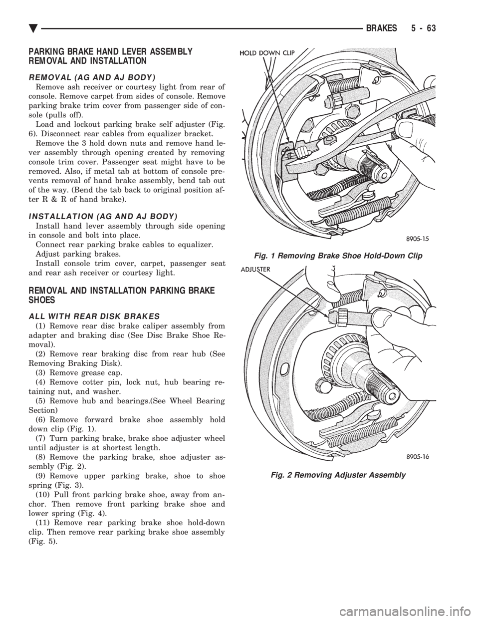
Section) (6) Remove forward brake shoe assembly hold
down clip (Fig. 1). (7) Turn parking brake, brake shoe adjuster wheel
until adjuster is at shortest length. (8) Remove the parking brake, shoe adjuster as-
sembly (Fig. 2). (9) Remove upper parking brake, shoe to shoe
spring (Fig. 3). (10) Pull front parking brake shoe, away from an-
chor. Then remove front parking brake shoe and
lower spring (Fig. 4). (11) Remove rear parking brake shoe hold-down
clip. Then remove rear parking brake shoe assembly
(Fig. 5).
Fig. 1 Removing Brake Shoe Hold-Down Clip
Fig. 2 Removing Adjuster Assembly
Ä BRAKES 5 - 63