brake light CHEVROLET DYNASTY 1993 Owner's Manual
[x] Cancel search | Manufacturer: CHEVROLET, Model Year: 1993, Model line: DYNASTY, Model: CHEVROLET DYNASTY 1993Pages: 2438, PDF Size: 74.98 MB
Page 216 of 2438
MASTER CYLINDER INDEX
page page
Brake Fluid Level Sensor .................. 66
General Information ....................... 66 Master Cylinder Service Procedures
.......... 67
Testing the Master Cylinder ................. 66
GENERAL INFORMATION
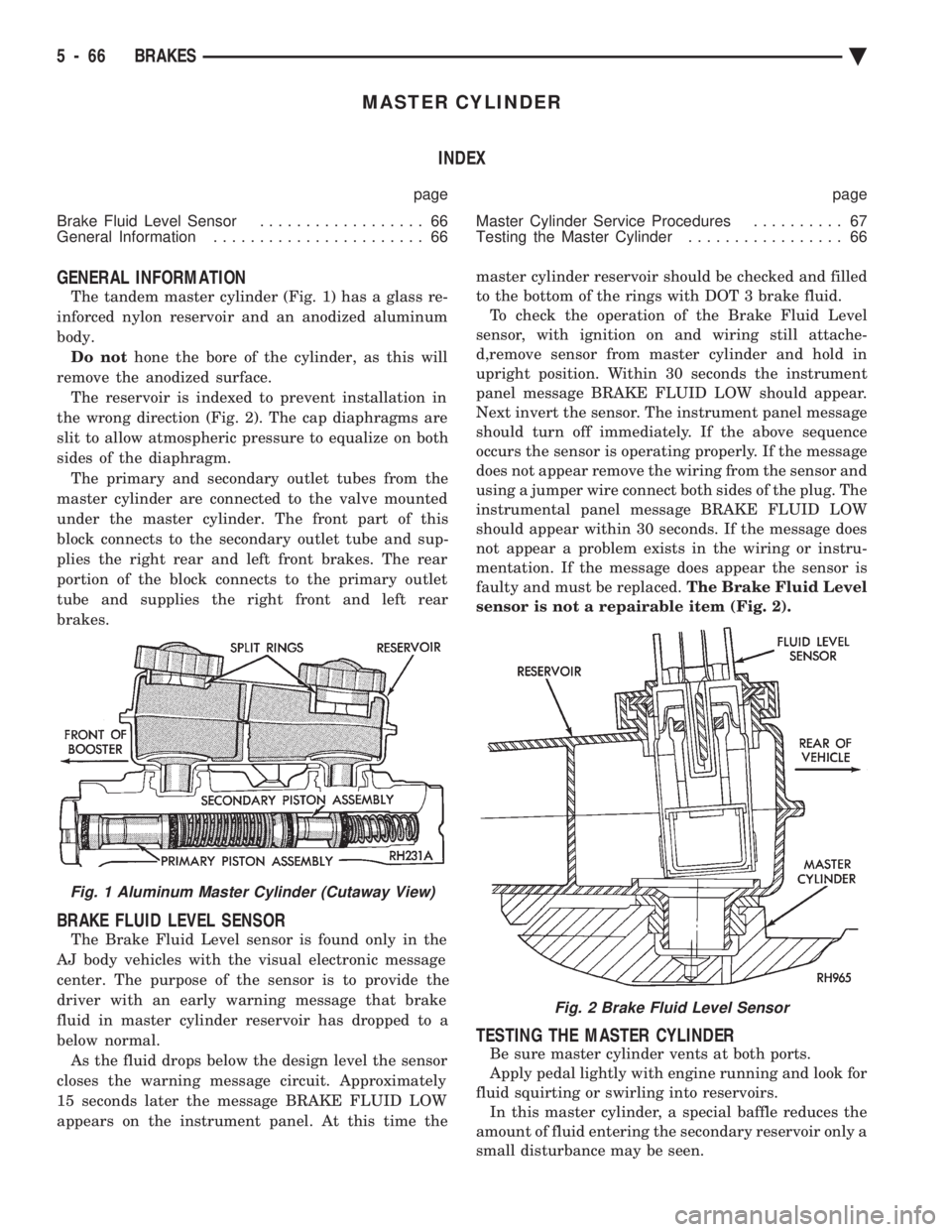
The tandem master cylinder (Fig. 1) has a glass re-
inforced nylon reservoir and an anodized aluminum
body. Do not hone the bore of the cylinder, as this will
remove the anodized surface. The reservoir is indexed to prevent installation in
the wrong direction (Fig. 2). The cap diaphragms are
slit to allow atmospheric pressure to equalize on both
sides of the diaphragm. The primary and secondary outlet tubes from the
master cylinder are connected to the valve mounted
under the master cylinder. The front part of this
block connects to the secondary outlet tube and sup-
plies the right rear and left front brakes. The rear
portion of the block connects to the primary outlet
tube and supplies the right front and left rear
brakes.
BRAKE FLUID LEVEL SENSOR
The Brake Fluid Level sensor is found only in the
AJ body vehicles with the visual electronic message
center. The purpose of the sensor is to provide the
driver with an early warning message that brake
fluid in master cylinder reservoir has dropped to a
below normal. As the fluid drops below the design level the sensor
closes the warning message circuit. Approximately
15 seconds later the message BRAKE FLUID LOW
appears on the instrument panel. At this time the master cylinder reservoir should be checked and filled
to the bottom of the rings with DOT 3 brake fluid. To check the operation of the Brake Fluid Level
sensor, with ignition on and wiring still attache-
d,remove sensor from master cylinder and hold in
upright position. Within 30 seconds the instrument
panel message BRAKE FLUID LOW should appear.
Next invert the sensor. The instrument panel message
should turn off immediately. If the above sequence
occurs the sensor is operating properly. If the message
does not appear remove the wiring from the sensor and
using a jumper wire connect both sides of the plug. The
instrumental panel message BRAKE FLUID LOW
should appear within 30 seconds. If the message does
not appear a problem exists in the wiring or instru-
mentation. If the message does appear the sensor is
faulty and must be replaced. The Brake Fluid Level
sensor is not a repairable item (Fig. 2).
TESTING THE MASTER CYLINDER
Be sure master cylinder vents at both ports.
Apply pedal lightly with engine running and look for
fluid squirting or swirling into reservoirs. In this master cylinder, a special baffle reduces the
amount of fluid entering the secondary reservoir only a
small disturbance may be seen.
Fig. 1 Aluminum Master Cylinder (Cutaway View)
Fig. 2 Brake Fluid Level Sensor
5 - 66 BRAKES Ä
Page 220 of 2438
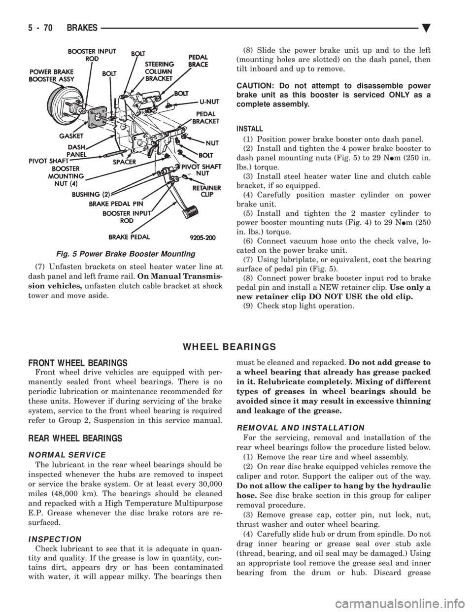
(7) Unfasten brackets on steel heater water line at
dash panel and left frame rail. On Manual Transmis-
sion vehicles, unfasten clutch cable bracket at shock
tower and move aside. (8) Slide the power brake unit up and to the left
(mounting holes are slotted) on the dash panel, then
tilt inboard and up to remove.
CAUTION: Do not attempt to disassemble power
brake unit as this booster is serviced ONLY as a
complete assembly.
INSTALL (1) Position power brake booster onto dash panel.
(2) Install and tighten the 4 power brake booster to
dash panel mounting nuts (Fig. 5) to 29 N Im (250 in.
lbs.) torque. (3) Install steel heater water line and clutch cable
bracket, if so equipped. (4) Carefully position master cylinder on power
brake unit. (5) Install and tighten the 2 master cylinder to
power booster mounting nuts (Fig. 4) to 29 N Im (250
in. lbs.) torque. (6) Connect vacuum hose onto the check valve, lo-
cated on the power brake unit. (7) Using lubriplate, or equivalent, coat the bearing
surface of pedal pin (Fig. 5). (8) Connect power brake booster input rod to brake
pedal pin and install a NEW retainer clip. Use only a
new retainer clip DO NOT USE the old clip. (9) Check stop light operation.
WHEEL BEARINGS
FRONT WHEEL BEARINGS
Front wheel drive vehicles are equipped with per-
manently sealed front wheel bearings. There is no
periodic lubrication or maintenance recommended for
these units. However if during servicing of the brake
system, service to the front wheel bearing is required
refer to Group 2, Suspension in this service manual.
REAR WHEEL BEARINGS
NORMAL SERVICE
The lubricant in the rear wheel bearings should be
inspected whenever the hubs are removed to inspect
or service the brake system. Or at least every 30,000
miles (48,000 km). The bearings should be cleaned
and repacked with a High Temperature Multipurpose
E.P. Grease whenever the disc brake rotors are re-
surfaced.
INSPECTION
Check lubricant to see that it is adequate in quan-
tity and quality. If the grease is low in quantity, con-
tains dirt, appears dry or has been contaminated
with water, it will appear milky. The bearings then must be cleaned and repacked.
Do not add grease to
a wheel bearing that already has grease packed
in it. Relubricate completely. Mixing of different
types of greases in wheel bearings should be
avoided since it may result in excessive thinning
and leakage of the grease.
REMOVAL AND INSTALLATION
For the servicing, removal and installation of the
rear wheel bearings follow the procedure listed below. (1) Remove the rear tire and wheel assembly.
(2) On rear disc brake equipped vehicles remove the
caliper and rotor. Support the caliper out of the way.
Do not allow the caliper to hang by the hydraulic
hose. See disc brake section in this group for caliper
removal procedure. (3) Remove grease cap, cotter pin, nut lock, nut,
thrust washer and outer wheel bearing. (4) Carefully slide hub or drum from spindle. Do not
drag inner bearing or grease seal over stub axle
(thread, bearing, and oil seal may be damaged.) Using
an appropriate tool remove the grease seal and inner
bearing from the drum or hub. Discard grease
Fig. 5 Power Brake Booster Mounting
5 - 70 BRAKES Ä
Page 224 of 2438
difference is that power assist is provided by hydrau-
lic power assist instead of the conventional vacuum
assist. If a wheel locking tendency is noticed during a
brake application, the system will enter Anti-Lock
mode. During Anti-Lock braking, hydraulic pressure
in the four wheel circuits is modulated to prevent
any wheel from locking. Each wheel has a set of elec-
trical solenoid valves and a hydraulic line to provide
hydraulic modulation. For vehicle stability, though
both rear wheel valves receive the same electrical
signal. The system can build, hold or reduce pressure
at each wheel. Depending on the signals generated
by the wheel speed sensors (WSS) at each wheel and
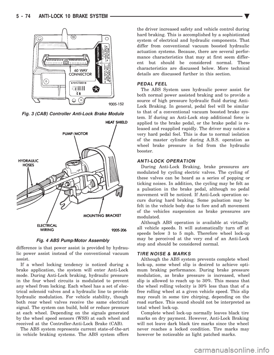
received at the Controller-Anti-Lock Brake (CAB). The ABS system represents current state-of-the-art
in vehicle braking systems. The ABS system offers the driver increased safety and vehicle control during
hard braking. This is accomplished by a sophisticated
system of electrical and hydraulic components. That
differ from conventional vacuum boosted hydraulic
actuation systems. Because, there are several perfor-
mance characteristics that may at first seem differ-
ent but should be considered normal. These
characteristics are discussed below. More technical
details are discussed further in this section.
PEDAL FEEL
The ABS System uses hydraulic power assist for
both normal power assisted braking and to provide a
source of high pressure hydraulic fluid during Anti-
Lock Braking. In general, pedal feel will be similar
to that of a conventional vacuum boosted brake sys-
tem. If during an Anti-Lock stop additional force is
applied to the brake pedal, or the brake pedal is re-
leased and reapplied rapidly. The driver may notice a
very hard pedal feel. This is due to normal isolation
of the master cylinder during A.B.S. operation as
wheel brake pressure is fed from the hydraulic
booster.
ANTI-LOCK OPERATION
During Anti-Lock Braking, brake pressures are
modulated by cycling electric valves. The cycling of
these valves can be heard as a series of popping or
ticking noises. In addition, the cycling may be felt as
a pulsation in the brake pedal, although no pedal
movement will be noticed. If Anti-Lock operation oc-
curs during hard braking. Some pulsation may be
felt in the vehicle body due to fore and aft movement
of the vehicles suspension as brake pressures are
modulated. Although ABS operation is available at virtually
all vehicle speeds. It will automatically turn off at
speeds below 3 to 5 mph. Therefore wheel lock-up
may be perceived at the very end of an Anti-Lock
stop and should be considered normal.
TIRE NOISE & MARKS
Although the ABS system prevents complete wheel
lock-up, some wheel slip is desired to achieve opti-
mum braking performance. During brake pressure
modulation, as brake pressure is increased, wheel
slip is allowed to reach up to 30%. This means that
the wheel rolling velocity is 30% less than that of a
free rolling wheel at a given vehicle speed. This slip
may result in some tire chirping, depending on the
road surface. This sound should not be interpreted as
total wheel lock-up. Complete wheel lock-up normally leaves black tire
marks on dry payment. However, Anti-Lock Braking
will not leave dark black tire marks since the wheel
never reaches a locked condition. Tire marks may
however be noticeable as light patched marks.
Fig. 3 (CAB) Controller Anti-Lock Brake Module
Fig. 4 ABS Pump/Motor Assembly
5 - 74 ANTI-LOCK 10 BRAKE SYSTEM Ä
Page 227 of 2438
circuits are hydraulically isolated so a leak or mal-
function in one circuit will allow continued braking
ability in the other.When force is applied to the brake pedal, the input
pushrod applies force to the boost control valve. As
the boost control valve is moved, it allows the pres-
surized fluid from the accumulator to flow into the
master cylinder booster chamber. The pressure gen-
erated in the booster chamber is directly propor-
tioned to the brake pedal force exerted by the driver.
This pressure in the booster servo in turn applies
pressure to the primary master cylinder piston that
in turn applies pressure to the secondary master cyl-
inder piston. The pressure generated in the primary
and secondary circuits are used to apply the brakes
during normal braking.
WARNING: THE HYDRAULIC ACCUMULATORS
CONTAIN BRAKE FLUID AND NITROGEN GAS AT
HIGH PRESSURE. CERTAIN PORTIONS OF THE
BRAKE SYSTEM ALSO CONTAIN BRAKE FLUID AT
HIGH PRESSURE. REMOVAL OR DISASSEMBLY
MAY RESULT IN PERSONAL INJURY AND IM-
PROPER SYSTEM OPERATION. REFER TO THE AP-
PROPRIATE SERVICE MANUAL FOR PROPER
SERVICE PROCEDURES.
HYDRAULIC BLADDER ACCUMULATOR
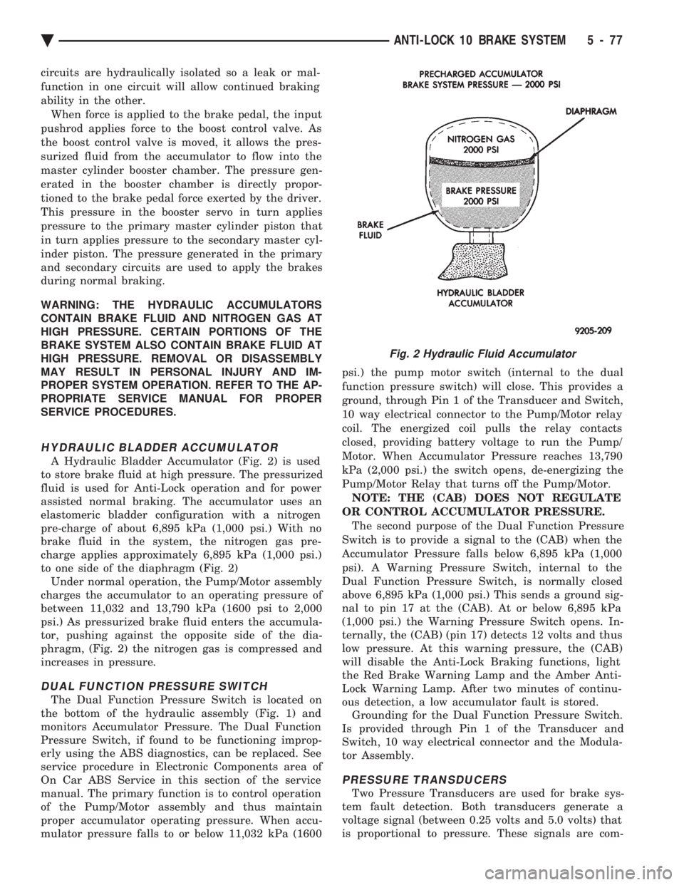
A Hydraulic Bladder Accumulator (Fig. 2) is used
to store brake fluid at high pressure. The pressurized
fluid is used for Anti-Lock operation and for power
assisted normal braking. The accumulator uses an
elastomeric bladder configuration with a nitrogen
pre-charge of about 6,895 kPa (1,000 psi.) With no
brake fluid in the system, the nitrogen gas pre-
charge applies approximately 6,895 kPa (1,000 psi.)
to one side of the diaphragm (Fig. 2) Under normal operation, the Pump/Motor assembly
charges the accumulator to an operating pressure of
between 11,032 and 13,790 kPa (1600 psi to 2,000
psi.) As pressurized brake fluid enters the accumula-
tor, pushing against the opposite side of the dia-
phragm, (Fig. 2) the nitrogen gas is compressed and
increases in pressure.
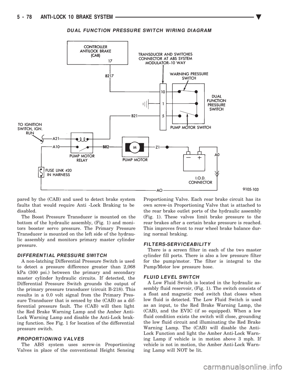
DUAL FUNCTION PRESSURE SWITCH
The Dual Function Pressure Switch is located on
the bottom of the hydraulic assembly (Fig. 1) and
monitors Accumulator Pressure. The Dual Function
Pressure Switch, if found to be functioning improp-
erly using the ABS diagnostics, can be replaced. See
service procedure in Electronic Components area of
On Car ABS Service in this section of the service
manual. The primary function is to control operation
of the Pump/Motor assembly and thus maintain
proper accumulator operating pressure. When accu-
mulator pressure falls to or below 11,032 kPa (1600 psi.) the pump motor switch (internal to the dual
function pressure switch) will close. This provides a
ground, through Pin 1 of the Transducer and Switch,
10 way electrical connector to the Pump/Motor relay
coil. The energized coil pulls the relay contacts
closed, providing battery voltage to run the Pump/
Motor. When Accumulator Pressure reaches 13,790
kPa (2,000 psi.) the switch opens, de-energizing the
Pump/Motor Relay that turns off the Pump/Motor. NOTE: THE (CAB) DOES NOT REGULATE
OR CONTROL ACCUMULATOR PRESSURE. The second purpose of the Dual Function Pressure
Switch is to provide a signal to the (CAB) when the
Accumulator Pressure falls below 6,895 kPa (1,000
psi). A Warning Pressure Switch, internal to the
Dual Function Pressure Switch, is normally closed
above 6,895 kPa (1,000 psi.) This sends a ground sig-
nal to pin 17 at the (CAB). At or below 6,895 kPa
(1,000 psi.) the Warning Pressure Switch opens. In-
ternally, the (CAB) (pin 17) detects 12 volts and thus
low pressure. At this warning pressure, the (CAB)
will disable the Anti-Lock Braking functions, light
the Red Brake Warning Lamp and the Amber Anti-
Lock Warning Lamp. After two minutes of continu-
ous detection, a low accumulator fault is stored. Grounding for the Dual Function Pressure Switch.
Is provided through Pin 1 of the Transducer and
Switch, 10 way electrical connector and the Modula-
tor Assembly.
PRESSURE TRANSDUCERS
Two Pressure Transducers are used for brake sys-
tem fault detection. Both transducers generate a
voltage signal (between 0.25 volts and 5.0 volts) that
is proportional to pressure. These signals are com-
Fig. 2 Hydraulic Fluid Accumulator
Ä ANTI-LOCK 10 BRAKE SYSTEM 5 - 77
Page 228 of 2438
pared by the (CAB) and used to detect brake system
faults that would require Anti -Lock Braking to be
disabled.The Boost Pressure Transducer is mounted on the
bottom of the hydraulic assembly, (Fig. 1) and moni-
tors booster servo pressure. The Primary Pressure
Transducer is mounted on the left side of the hydrau-
lic assembly and monitors primary master cylinder
pressure.
DIFFERENTIAL PRESSURE SWITCH
A non-latching Differential Pressure Switch is used
to detect a pressure difference greater than 2,068
kPa (300 psi.) between the primary and secondary
master cylinder hydraulic circuits. If detected, the
Differential Pressure Switch grounds the output of
the primary pressure transducer (circuit B-218). This
results in a 0.0 volt signal from the Primary Pres-
sure Transducer that is sensed by the (CAB) as a dif-
ferential pressure fault. The (CAB) will then light
the Red Brake Warning Lamp and the Amber Anti-
Lock Warning Lamp and disable the Anti-Lock brak-
ing function. See Fig. 1 for location of the differential
pressure switch.
PROPORTIONING VALVES
The ABS system uses screw-in Proportioning
Valves in place of the conventional Height Sensing Proportioning Valve. Each rear brake circuit has its
own screw-in Proportioning Valve that is attached to
the rear brake outlet ports of the hydraulic assembly
(Fig. 1). These valves limit brake pressure to the
rear brakes after a certain brake pressure is reached.
This improves front to rear wheel brake balance dur-
ing normal braking.
FILTERS-SERVICEABILITY
There is a screen filter in each of the two master
cylinder fill ports. There is also a low pressure filter
for the pump/motor. The filter is integral to the
Pump/Motor low pressure hose.
FLUID LEVEL SWITCH
A Low Fluid Switch is located in the hydraulic as-
sembly fluid reservoir, (Fig. 1). The switch consists of
a float and magnetic reed switch that closes when
low fluid is detected. The Low Fluid Switch is used
as an input, to the Red Brake Warning Lamp, the
(CAB), and the EVIC (if so equipped). When a low
fluid condition exists the switch will close, grounding
the low fluid circuit and illuminating the Red Brake
Warning Lamp. The (CAB) will disable the Anti-
Lock Function and light the Amber Anti-Lock Warn-
ing Lamp if vehicle is in motion above 3 mph. If
vehicle is not in motion, the Amber Anti-Lock Warn-
ing Lamp will NOT be lit.
DUAL FUNCTION PRESSURE SWITCH WIRING DIAGRAM
5 - 78 ANTI-LOCK 10 BRAKE SYSTEM Ä
Page 232 of 2438
The primary functions of the (CAB) are:
² (1) Detect wheel locking tendencies.
² (2) Control fluid modulation to the brakes while in
Anti-Lock mode.
² (3) Monitor the system for proper operation.
² (4) Provide communication to the DRB II while in
diagnostic mode. The (CAB) continuously monitors the speed of each
wheel, through the signals generated at the Wheel
Speed Sensors, to determine if any wheel is begin-
ning to lock. When a wheel locking tendency is de-
tected, the (CAB) will isolate the master cylinder
from the wheel brakes. This is done by activating the
Isolation Valves. The (CAB) then commands the ap-
propriate Build or Decay valves to modulate brake
fluid pressure in some or all of the hydraulic circuits.
The fluid used for modulation comes from the booster
servo circuit. The (CAB) continues to control pres-
sure in individual hydraulic circuits until a locking
tendency is no longer present. The (ABS) system is constantly monitored by the
(CAB) for proper operation. If the (CAB) detects a
fault, it can disable the Anti-Lock braking function.
Depending on the fault, the (CAB) will light one or
both of the brake warning lamps. The (CAB) contains a System Diagnostic Program
which triggers the brake system warning lamps
when a system fault is detected. Faults are stored in
a diagnostic program memory. There are 19 fault
codes that may be stored in the (CAB) and displayed
through the DRB II. These fault codes will remain in
the (CAB) memory even after the ignition has been
turned off. These fault codes will remain in memory
until they are cleared with the DRB II, or automati-
cally erased from the memory after (50) ignition
switch on/off cycles.
CONTROLLER ANTI-LOCK BRAKE (INPUTS)
² Four wheel speed sensors.
² Boost pressure transducer.
² Primary pressure transducer.
² Low fluid level switch.
² Differential pressure switch.
² Parking brake switch.
² Dual function pressure switch (warning pressure
only)
² Stop lamp switch.
² Ignition switch.
² System relay voltage.
² Ground.
² Low Accumulator
CONTROLLER ANTI-LOCK BRAKE (OUTPUTS)
²Ten modulator valves-3 decay, 3 build and 4 isola-
tion.
² Red Brake warning lamp.
² Amber Anti-Lock Warning Lamp.
² System relay actuation. ²
Diagnostic communication.
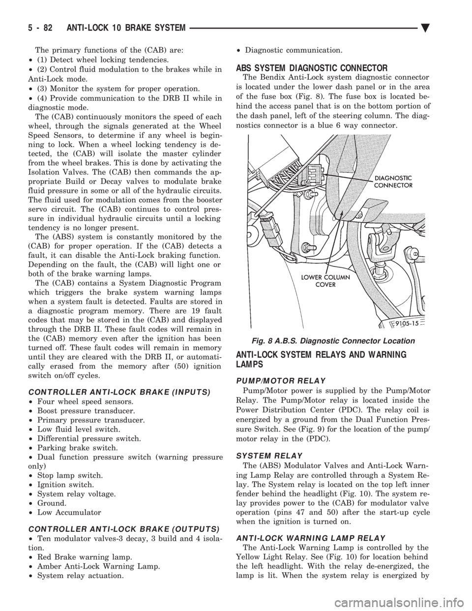
ABS SYSTEM DIAGNOSTIC CONNECTOR
The Bendix Anti-Lock system diagnostic connector
is located under the lower dash panel or in the area
of the fuse box (Fig. 8). The fuse box is located be-
hind the access panel that is on the bottom portion of
the dash panel, left of the steering column. The diag-
nostics connector is a blue 6 way connector.
ANTI-LOCK SYSTEM RELAYS AND WARNING
LAMPS
PUMP/MOTOR RELAY
Pump/Motor power is supplied by the Pump/Motor
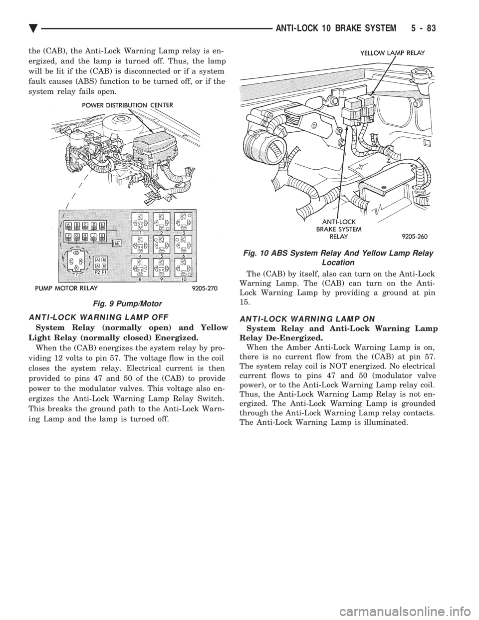
Relay. The Pump/Motor relay is located inside the
Power Distribution Center (PDC). The relay coil is
energized by a ground from the Dual Function Pres-
sure Switch. See (Fig. 9) for the location of the pump/
motor relay in the (PDC).
SYSTEM RELAY
The (ABS) Modulator Valves and Anti-Lock Warn-
ing Lamp Relay are controlled through a System Re-
lay. The System relay is located on the top left inner
fender behind the headlight (Fig. 10). The system re-
lay provides power to the (CAB) for modulator valve
operation (pins 47 and 50) after the start-up cycle
when the ignition is turned on.
ANTI-LOCK WARNING LAMP RELAY
The Anti-Lock Warning Lamp is controlled by the
Yellow Light Relay. See (Fig. 10) for location behind
the left headlight. With the relay de-energized, the
lamp is lit. When the system relay is energized by
Fig. 8 A.B.S. Diagnostic Connector Location
5 - 82 ANTI-LOCK 10 BRAKE SYSTEM Ä
Page 233 of 2438
the (CAB), the Anti-Lock Warning Lamp relay is en-
ergized, and the lamp is turned off. Thus, the lamp
will be lit if the (CAB) is disconnected or if a system
fault causes (ABS) function to be turned off, or if the
system relay fails open.
ANTI-LOCK WARNING LAMP OFF
System Relay (normally open) and Yellow
Light Relay (normally closed) Energized. When the (CAB) energizes the system relay by pro-
viding 12 volts to pin 57. The voltage flow in the coil
closes the system relay. Electrical current is then
provided to pins 47 and 50 of the (CAB) to provide
power to the modulator valves. This voltage also en-
ergizes the Anti-Lock Warning Lamp Relay Switch.
This breaks the ground path to the Anti-Lock Warn-
ing Lamp and the lamp is turned off. The (CAB) by itself, also can turn on the Anti-Lock
Warning Lamp. The (CAB) can turn on the Anti-
Lock Warning Lamp by providing a ground at pin
15.
ANTI-LOCK WARNING LAMP ON
System Relay and Anti-Lock Warning Lamp
Relay De-Energized. When the Amber Anti-Lock Warning Lamp is on,
there is no current flow from the (CAB) at pin 57.
The system relay coil is NOT energized. No electrical
current flows to pins 47 and 50 (modulator valve
power), or to the Anti-Lock Warning Lamp relay coil.
Thus, the Anti-Lock Warning Lamp Relay is not en-
ergized. The Anti-Lock Warning Lamp is grounded
through the Anti-Lock Warning Lamp relay contacts.
The Anti-Lock Warning Lamp is illuminated.
Fig. 9 Pump/Motor
Fig. 10 ABS System Relay And Yellow Lamp Relay Location
Ä ANTI-LOCK 10 BRAKE SYSTEM 5 - 83
Page 243 of 2438
DRIVE-OFF CYCLE
The DRIVE-OFF CYCLE takes place when the ve-
hicle reaches about 3 miles per hour the first time af-
ter an ignition reset. During this test, the modulator
solenoid valves are activated briefly to test their
function. The DRIVE-OFF CYCLE will be bypassed
if you drive-off with the service brake pedal de-
pressed.
LATCHING VERSUS NON-LATCHING FAULTS
Some faults detected by the (CAB) are latching.
The fault is latched and (ABS) function is disabled
until the ignition switch is reset (turned OFF/ON).
Thus (ABS) function is disabled even if the original
fault has disappeared during the ignition cycle in
which it occurred. Other faults are non-latching; any
warning lights that are turned on are only on as long
as the fault condition exists. As soon as the condition
goes away. The Amber Anti-Lock Warning Light is
turned off. Although a fault code will be set in most
cases. (Example:low accumulator fault will not be
stored for a time of 2 minutes after the fault is de-
tected).
BENDIX ABS SYSTEMS DIAGNOSTICS
The Bendix Anti-Lock 10 Brake System diagnos-
tics. Beyond the basic mechanical diagnostics, sys-
tems and components covered earlier in this section,
is accomplished by using the DRB II diagnostic
tester. See testing procedures outlined in the Bendix
Anti-Lock 10 Diagnostics Manual for the 1993 M.Y. Please reference the above mentioned manual. For
any further diagnostic service procedures that are re-
quired on the Bendix Anti-Lock 10 Brake System, re-
quiring the use of the DRB II diagnostic tester.
ON CAR HYDRAULIC ABS COMPONENT SERVICE
WARNING: FAILURE TO FULLY DE-PRESSURIZE
THE HYDRAULIC ACCUMULATOR BEFORE PER-
FORMING HYDRAULIC SYSTEM SERVICE OPERA-
TIONS. COULD RESULT IN INJURY TO SERVICE
PERSONNEL AND OR DAMAGE TO PAINTED SUR-
FACES. SEE SECTION 2 FOR ADDITIONAL WARN-
INGS AND CAUTIONS.
GENERAL SERVICE PRECAUTIONS
The following are general precautions that should
be observed when servicing the Anti-Lock Brake Sys-
tem and/or other vehicle systems. Failure to observe
these precautions may result in Anti-Lock brake sys-
tem damage. If welding work is to be performed on the vehicle,
using an electric arc welder, the (CAB) connector
should be disconnected during the welding operation. The (CAB) or hydraulic assembly connector should
never be connected or disconnected with the ignition
switch in the ONposition.
Many components of the Anti-Lock brake system are
not serviceable and must be replaced as an assembly.
Do not attempt to disassemble any component
that is not designed to be a serviced component.
DE-PRESSURIZING HYDRAULIC ACCUMULA- TOR
The pump/motor assembly will keep the hydraulic
accumulator charged to approximately 11,032 and
13,790 kPa (1600 and 2000 psi) any time that the
ignition is in the ON position. The pump/motor assem-
bly cannot run if the ignition is off or if either battery
cable is disconnected. Unless otherwise specified, the hydraulic accumula-
tor should be de-pressurized before disassembling any
portion of the hydraulic system. The following proce-
dure should be used to relieve the pressure in the
hydraulic accumulator: (1) With ignition off, or either battery cable discon-
nected, pump the brake pedal a minimum of 40 times,
using approximately 222 N (50 lbs.) pedal force. A
noticeable change in pedal feel will occur, when the
accumulator is discharged. (2) When a definite increase in pedal effort is felt,
pump pedal a few additional times. This will insure
removal of all hydraulic pressure from the brake sys-
tem.
CHECKING BRAKE FLUID LEVEL
CAUTION: Use only brake fluid conforming to DOT 3
specifications such as Mopar Tor Equivalent. Do not
use any fluid in the brake hydraulic system, which
contains a petroleum base. Do not use a container
which has been used for petroleum based fluids or a
container that is wet with water. Petroleum based
fluids will cause swelling and distortion of rubber
parts in the hydraulic brake system and water will mix
with brake fluid, lowering the fluid boiling point. Keep
all brake fluid containers tightly capped to prevent
contamination.
The hydraulic assembly is equipped with a plastic
fluid reservoir, with a filter/strainer located in the filler
neck of each reservoir section. The Anti-Lock brake system requires that the hy-
draulic accumulator be de-pressurized when checking
the fluid level. To check the brake fluid level, the
following procedure should be used: (1) With the ignition off, de-pressurize the hydraulic
accumulator by applying the brake pedal approxi-
mately 40 times, using a pedal force of approximately
220 N (50 lbs.). A noticeable change in pedal feel will
occur when the accumulator is de-
Ä ANTI-LOCK 10 BRAKE SYSTEM 5 - 93
Page 265 of 2438
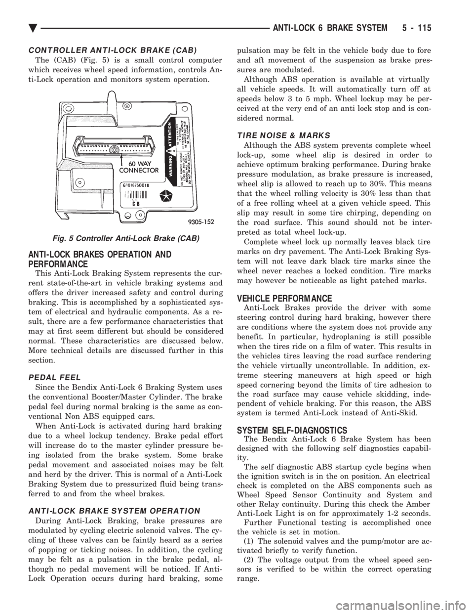
CONTROLLER ANTI-LOCK BRAKE (CAB)
The (CAB) (Fig. 5) is a small control computer
which receives wheel speed information, controls An-
ti-Lock operation and monitors system operation.
ANTI-LOCK BRAKES OPERATION AND
PERFORMANCE
This Anti-Lock Braking System represents the cur-
rent state-of-the-art in vehicle braking systems and
offers the driver increased safety and control during
braking. This is accomplished by a sophisticated sys-
tem of electrical and hydraulic components. As a re-
sult, there are a few performance characteristics that
may at first seem different but should be considered
normal. These characteristics are discussed below.
More technical details are discussed further in this
section.
PEDAL FEEL
Since the Bendix Anti-Lock 6 Braking System uses
the conventional Booster/Master Cylinder. The brake
pedal feel during normal braking is the same as con-
ventional Non ABS equipped cars. When Anti-Lock is activated during hard braking
due to a wheel lockup tendency. Brake pedal effort
will increase do to the master cylinder pressure be-
ing isolated from the brake system. Some brake
pedal movement and associated noises may be felt
and herd by the driver. This is normal of a Anti-Lock
Braking System due to pressurized fluid being trans-
ferred to and from the wheel brakes.
ANTI-LOCK BRAKE SYSTEM OPERATION
During Anti-Lock Braking, brake pressures are
modulated by cycling electric solenoid valves. The cy-
cling of these valves can be faintly heard as a series
of popping or ticking noises. In addition, the cycling
may be felt as a pulsation in the brake pedal, al-
though no pedal movement will be noticed. If Anti-
Lock Operation occurs during hard braking, some pulsation may be felt in the vehicle body due to fore
and aft movement of the suspension as brake pres-
sures are modulated.
Although ABS operation is available at virtually
all vehicle speeds. It will automatically turn off at
speeds below 3 to 5 mph. Wheel lockup may be per-
ceived at the very end of an anti lock stop and is con-
sidered normal.
TIRE NOISE & MARKS
Although the ABS system prevents complete wheel
lock-up, some wheel slip is desired in order to
achieve optimum braking performance. During brake
pressure modulation, as brake pressure is increased,
wheel slip is allowed to reach up to 30%. This means
that the wheel rolling velocity is 30% less than that
of a free rolling wheel at a given vehicle speed. This
slip may result in some tire chirping, depending on
the road surface. This sound should not be inter-
preted as total wheel lock-up. Complete wheel lock up normally leaves black tire
marks on dry pavement. The Anti-Lock Braking Sys-
tem will not leave dark black tire marks since the
wheel never reaches a locked condition. Tire marks
may however be noticeable as light patched marks.
VEHICLE PERFORMANCE
Anti-Lock Brakes provide the driver with some
steering control during hard braking, however there
are conditions where the system does not provide any
benefit. In particular, hydroplaning is still possible
when the tires ride on a film of water. This results in
the vehicles tires leaving the road surface rendering
the vehicle virtually uncontrollable. In addition, ex-
treme steering maneuvers at high speed or high
speed cornering beyond the limits of tire adhesion to
the road surface may cause vehicle skidding, inde-
pendent of vehicle braking. For this reason, the ABS
system is termed Anti-Lock instead of Anti-Skid.
SYSTEM SELF-DIAGNOSTICS
The Bendix Anti-Lock 6 Brake System has been
designed with the following self diagnostics capabil-
ity. The self diagnostic ABS startup cycle begins when
the ignition switch is in the on position. An electrical
check is completed on the ABS components such as
Wheel Speed Sensor Continuity and System and
other Relay continuity. During this check the Amber
Anti-Lock Light is on for approximately 1-2 seconds. Further Functional testing is accomplished once
the vehicle is set in motion. (1) The solenoid valves and the pump/motor are ac-
tivated briefly to verify function. (2) The voltage output from the wheel speed sen-
sors is verified to be within the correct operating
range.
Fig. 5 Controller Anti-Lock Brake (CAB)
Ä ANTI-LOCK 6 BRAKE SYSTEM 5 - 115
Page 266 of 2438
If the vehicle is not set in motion within 3 minutes
from the time the ignition switch is set in the on po-
sition. The solenoid test is bypassed but the pump/
motor is activated briefly to verify that it is
operating correctly.
WARNING SYSTEMS OPERATION
The ABS system uses an Amber Anti-Lock Warn-
ing Lamp, located in the instrument cluster. The
purpose of the warning lamp is discussed in detail
below. The Amber Anti-Lock Warning Light will turn on
when the (CAB) detects a condition which results in
a shutdown of the Anti-Lock function. The Amber
Anti-Lock Warning Lamp is normally on until the
(CAB) completes its self tests and turns the lamp off
(approximately 1-2 seconds). When the Amber Anti-
Lock Warning Light is on only the Anti-Lock func-
tion of the brake system if affected. The standard
brake system and the ability to stop the car will not
be affected when only the Amber Anti-Lock Warning
Light is on.
NORMAL OPERATION OF WARNING LAMP
With the ignition in the Crank position, the Red
Brake Warning Lamp will turn on as a bulb check.
The Amber Anti-Lock Warning Lamp will stay on for
1-2 seconds then turn off. Once verification of the self
diagnosis is completed.
ANTI-LOCK BRAKE SYSTEM COMPONENTS
The following is a detailed description of the Anti-
Lock Brake System components. For information on
servicing the Four Wheel Disk Brake System, see the
standard Brake section of this Service Manual.
MODULATOR ASSEMBLY
WARNING: THE ONLY PART OF THE MODULATOR
ASSEMBLY THAT IS A SERVICEABLE COMPONENT
IS THE DELTA P SWITCH. THE REMAINING COM-
PONENTS OF THE MODULATOR ASSEMBLY ARE
NOT SERVICEABLE ITEMS. NO ATTEMPT SHOULD
BE MADE TO REMOVE OR SERVICE ANY OTHER
PARTS OF THE MODULATOR ASSEMBLY.
The Modulator Assembly (Fig. 1) is located under
the battery tray and is covered with an acid shield.
The Modulator Assembly contains the following com-
ponents for controlling the Anti-Lock braking sys-
tem. 2 Isolation Valves, 4 Build/Decay Valves, 4
Shuttle Orifices, 2 Fluid Sumps, 2 Accumulators, a
Pump/Motor and a Pressure Differential Valve/
Switch. Also attached to the Modulator Assembly are
4 brake tubes which are connected to an 8 way con-
nector block. The connector block is mounted to the
left frame rail below the master cylinder in the same location as the non ABS equipped combination valve.
The wheel brake lines are attached to the system via
the connector block.
ISOLATION VALVES
The Isolation Valves are used to isolate the master
cylinder from the rest of the brake hydraulic circuit
during an Anti-Lock stop. Two Isolation Valves are
used, one for the primary circuit and one for the sec-
ondary circuit. The Isolation Valves are spring
loaded in the released position. In the released posi-
tion the Isolation Valves provide a fluid path from
the master cylinder outputs to the wheel brakes via
the Build/Decay valves. When actuated it provides a
fluid path from the accumulator (which was charged
by the Pump/Motor during ABS operation) to the
Build/Decay valves through the Shuttle Orifices.
BUILD/DECAY VALVES
There are 4 Build/Decay valves, one for each
wheel. In the released position they provide a fluid
path from the wheel brakes to the Isolation Valve
through the shuttle orifices. In the actuated (decay)
position, they provide a fluid path from the wheel
brakes to the sump. The Build/Decay valves are
spring loaded in the released (build) position.
SHUTTLE ORIFICE
There are 4 Shuttle Orifice Valves, one for each
wheel. The Shuttle Orifice Valve is a hydraulically
actuated valve which shuttles when the Build/Decay
valve is actuated. Actuating of the Build/Decay valve
causes a pressure differential to be created across the
Shuttle Orifice Valve. This acts like placing an ori-
fice (restriction) in the line between the Isolation
Valve and the Build/Decay Valve. This restriction
provides a controlled build rate to each wheel brake
during an Anti-Lock stop. The Shuttle Orifice Valve
will remain in the orificed position until the ABS cy-
cle is complete. When the ABS cycle has been com-
pleted the Isolation and Build/Decay valves will
return to their released position which will equalize
the pressure across the Shuttle Orifice Valves. When
the pressure equalizes, the spring loaded Shuttle Or-
ifice valves will return to the unrestricted position.
FLUID SUMPS
There are two Fluid Sumps in the Hydraulic As-
sembly, one each for the primary and secondary hy-
draulic circuits. The Fluid Sumps store the brake
fluid that is decayed from the wheel brakes during
ABS cycle. This fluid is then pumped to an accumu-
lator and/or the hydraulic system in order to provide
build pressure. The typical pressure in the sumps is
50 psi, During ABS operation only.
5 - 116 ANTI-LOCK 6 BRAKE SYSTEM Ä