radio CHEVROLET DYNASTY 1993 User Guide
[x] Cancel search | Manufacturer: CHEVROLET, Model Year: 1993, Model line: DYNASTY, Model: CHEVROLET DYNASTY 1993Pages: 2438, PDF Size: 74.98 MB
Page 502 of 2438
(4) Check cavity H of the black connector for con-
tinuity to ground. (5) Check for tachometer signal from the power-
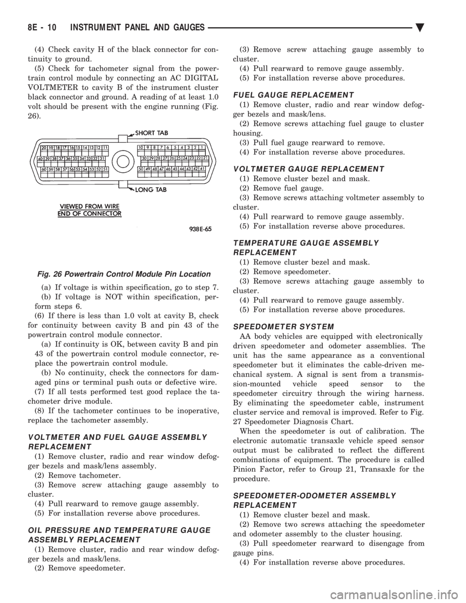
train control module by connecting an AC DIGITAL
VOLTMETER to cavity B of the instrument cluster
black connector and ground. A reading of at least 1.0
volt should be present with the engine running (Fig.
26).
(a) If voltage is within specification, go to step 7.
(b) If voltage is NOT within specification, per-
form steps 6.
(6) If there is less than 1.0 volt at cavity B, check
for continuity between cavity B and pin 43 of the
powertrain control module connector. (a) If continuity is OK, between cavity B and pin
43 of the powertrain control module connector, re-
place the powertrain control module. (b) No continuity, check the connectors for dam-
aged pins or terminal push outs or defective wire.
(7) If all tests performed test good replace the ta-
chometer drive module. (8) If the tachometer continues to be inoperative,
replace the tachometer assembly.
VOLTMETER AND FUEL GAUGE ASSEMBLY REPLACEMENT
(1) Remove cluster, radio and rear window defog-
ger bezels and mask/lens assembly. (2) Remove tachometer.
(3) Remove screw attaching gauge assembly to
cluster. (4) Pull rearward to remove gauge assembly.
(5) For installation reverse above procedures.
OIL PRESSURE AND TEMPERATURE GAUGEASSEMBLY REPLACEMENT
(1) Remove cluster, radio and rear window defog-
ger bezels and mask/lens. (2) Remove speedometer. (3) Remove screw attaching gauge assembly to
cluster. (4) Pull rearward to remove gauge assembly.
(5) For installation reverse above procedures.
FUEL GAUGE REPLACEMENT
(1) Remove cluster, radio and rear window defog-
ger bezels and mask/lens. (2) Remove screws attaching fuel gauge to cluster
housing. (3) Pull fuel gauge rearward to remove.
(4) For installation reverse above procedures.
VOLTMETER GAUGE REPLACEMENT
(1) Remove cluster bezel and mask.
(2) Remove fuel gauge.
(3) Remove screws attaching voltmeter assembly to
cluster. (4) Pull rearward to remove gauge assembly.
(5) For installation reverse above procedures.
TEMPERATURE GAUGE ASSEMBLY REPLACEMENT
(1) Remove cluster bezel and mask.
(2) Remove speedometer.
(3) Remove screws attaching gauge assembly to
cluster. (4) Pull rearward to remove gauge assembly.
(5) For installation reverse above procedures.
SPEEDOMETER SYSTEM
AA body vehicles are equipped with electronically
driven speedometer and odometer assemblies. The
unit has the same appearance as a conventional
speedometer but it eliminates the cable-driven me-
chanical system. A signal is sent from a transmis-
sion-mounted vehicle speed sensor to the
speedometer circuitry through the wiring harness.
By eliminating the speedometer cable, instrument
cluster service and removal is improved. Refer to Fig.
27 Speedometer Diagnosis Chart. When the speedometer is out of calibration. The
electronic automatic transaxle vehicle speed sensor
output must be calibrated to reflect the different
combinations of equipment. The procedure is called
Pinion Factor, refer to Group 21, Transaxle for the
procedure.
SPEEDOMETER-ODOMETER ASSEMBLY REPLACEMENT
(1) Remove cluster bezel and mask.
(2) Remove two screws attaching the speedometer
and odometer assembly to the cluster housing. (3) Pull speedometer rearward to disengage from
gauge pins. (4) For installation reverse above procedures.
Fig. 26 Powertrain Control Module Pin Location
8E - 10 INSTRUMENT PANEL AND GAUGES Ä
Page 504 of 2438
ELECTRONIC AUTOMATIC TRANSAXLE VEHICLE SPEED SENSOR REPLACEMENT
The output vehicle speed sensor is located to the
left of the manual shift lever. (1) Raise and support vehicle on safety stands.
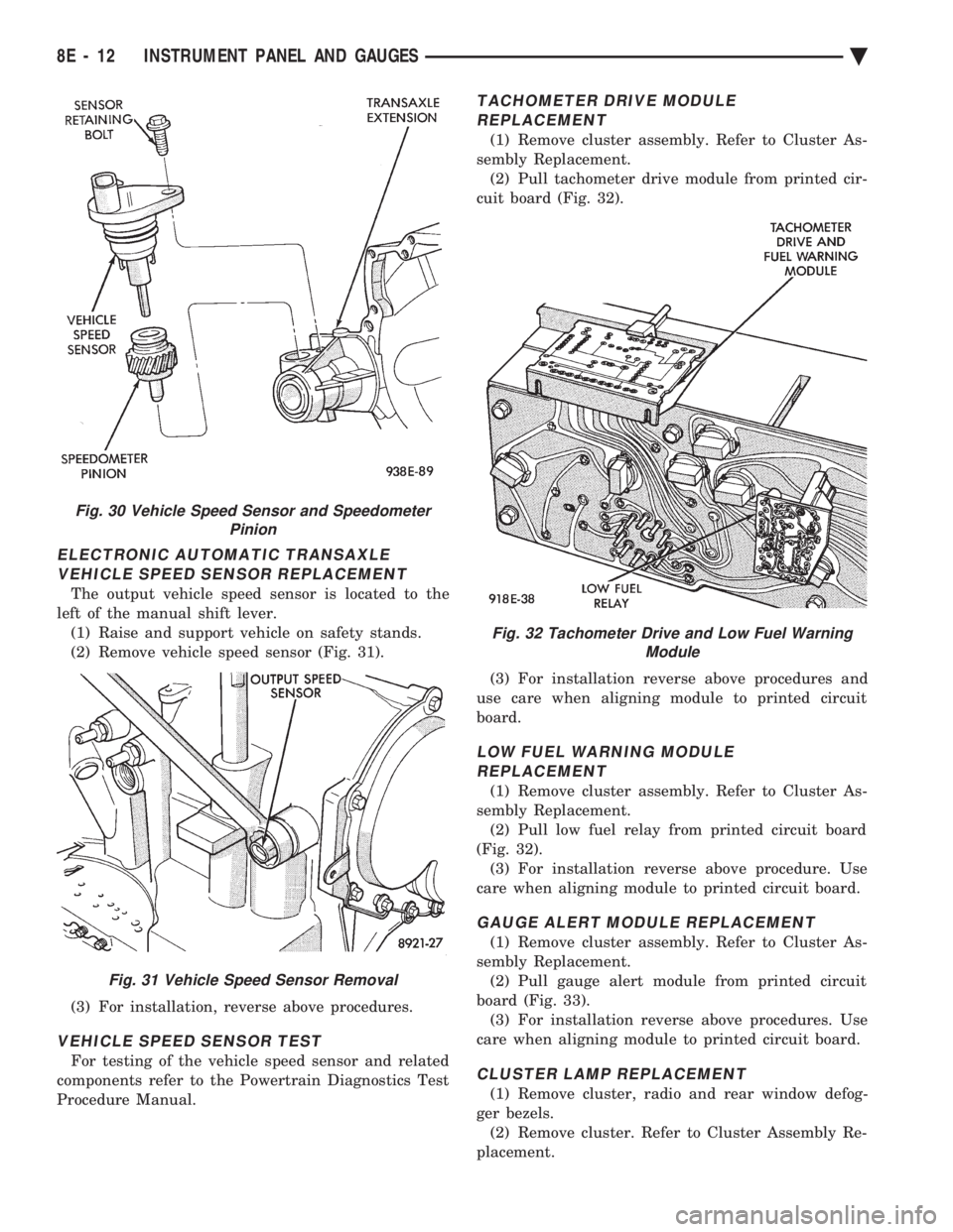
(2) Remove vehicle speed sensor (Fig. 31).
(3) For installation, reverse above procedures.
VEHICLE SPEED SENSOR TEST
For testing of the vehicle speed sensor and related
components refer to the Powertrain Diagnostics Test
Procedure Manual.
TACHOMETER DRIVE MODULE REPLACEMENT
(1) Remove cluster assembly. Refer to Cluster As-
sembly Replacement. (2) Pull tachometer drive module from printed cir-
cuit board (Fig. 32).
(3) For installation reverse above procedures and
use care when aligning module to printed circuit
board.
LOW FUEL WARNING MODULE REPLACEMENT
(1) Remove cluster assembly. Refer to Cluster As-
sembly Replacement. (2) Pull low fuel relay from printed circuit board
(Fig. 32). (3) For installation reverse above procedure. Use
care when aligning module to printed circuit board.
GAUGE ALERT MODULE REPLACEMENT
(1) Remove cluster assembly. Refer to Cluster As-
sembly Replacement. (2) Pull gauge alert module from printed circuit
board (Fig. 33). (3) For installation reverse above procedures. Use
care when aligning module to printed circuit board.
CLUSTER LAMP REPLACEMENT
(1) Remove cluster, radio and rear window defog-
ger bezels. (2) Remove cluster. Refer to Cluster Assembly Re-
placement.
Fig. 30 Vehicle Speed Sensor and Speedometer Pinion
Fig. 31 Vehicle Speed Sensor Removal
Fig. 32 Tachometer Drive and Low Fuel WarningModule
8E - 12 INSTRUMENT PANEL AND GAUGES Ä
Page 513 of 2438
(3) Remove four screws from ash receiver/cup
holder housing. (4) For installation reverse above procedures.
AIR CONDITIONING CONTROLREPLACEMENT
(1) Disconnect battery negative cable and isolate
or remove fuse #2 prior to removing switch or wires
may short to ground. (2) Remove center bezel. Disconnect ash receiver
lamp socket. (3) Remove glove box assembly. Refer to Glove Box
Assembly Replacement. (4) Reach through glove box opening and discon-
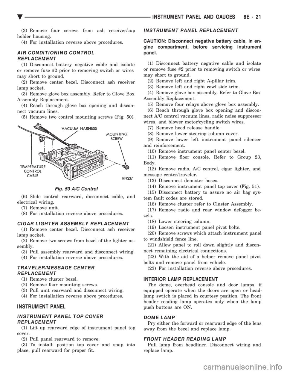
nect vacuum lines. (5) Remove two control mounting screws (Fig. 50).
(6) Slide control rearward, disconnect cable, and
electrical wiring. (7) Remove unit.
(8) For installation reverse above procedures.
CIGAR LIGHTER ASSEMBLY REPLACEMENT
(1) Remove center bezel. Disconnect ash receiver
lamp socket. (2) Remove two screws from bezel of the lighter as-
sembly. (3) Pull assembly rearward and disconnect wiring.
(4) For installation reverse above procedures.
TRAVELER/MESSAGE CENTER REPLACEMENT
(1) Remove cluster bezel.
(2) Remove four mounting screws.
(3) Pull unit rearward and disconnect wiring.
(4) For installation reverse above procedures.
INSTRUMENT PANEL
INSTRUMENT PANEL TOP COVER REPLACEMENT
(1) Lift up rearward edge of instrument panel top
cover. (2) Pull panel rearward to remove.
(3) To install: position top cover and snap into
place, pull rearward for proper fit.
INSTRUMENT PANEL REPLACEMENT
CAUTION: Disconnect negative battery cable, in en-
gine compartment, before servicing instrument
panel.
(1) Disconnect battery negative cable and isolate
or remove fuse #2 prior to removing switch or wires
may short to ground. (2) Remove left and right A-pillar trim.
(3) Remove left and right cowl side trim.
(4) Remove glove box assembly. Refer to Glove Box
Assembly Replacement. (5) Remove four relays above glove box assembly.
(6) Reach through glove box opening and discon-
nect A/C control vacuum lines, radio noise suppressor
wires, and blower motor/cycling switch wires. (7) Remove hood release handle.
(8) Remove lower steering column cover.
(9) Remove lower left instrument panel silencer
and reinforcement. (10) Remove instrument panel center bezel.
(11) Remove floor console. Refer to Group 23,
Body. (12) Remove radio, A/C control, cigar lighter, and
message center/traveler. (13) Disconnect demister hoses.
(14) Remove instrument panel top cover (Fig. 51).
(15) Disconnect battery to assure no air bag sys-
tem fault codes are stored. (16) Remove cluster refer to Cluster Assembly.
(17) Remove radio and rear window defogger be-
zels. (18) Lower steering column.
(19) Loosen instrument panel pivot bolts.
(20) Remove screws which attach instrument panel
to windshield fence line. (21) Allow panel to roll down slightly and discon-
nect remaining electrical connections. (22) With the aid of a helper remove panel pivot
bolts and remove panel from vehicle. (23) For installation reverse above procedures.
INTERIOR LAMP REPLACEMENT
The dome, overhead console and door lamps, if
equipped operate when the doors are open or head-
lamp switch is placed in courtesy position. The front
header reading lamp operates only when the lamp
push buttons are ON.
DOME LAMP
Pry either the forward or rearward edge of the lens
away from the bezel and replace lamp.
FRONT HEADER READING LAMP
Pull lamp from headliner. Disconnect wiring and
replace lamp.
Fig. 50 A/C Control
Ä INSTRUMENT PANEL AND GAUGES 8E - 21
Page 516 of 2438
MESSAGE CENTER
The message center is a car graphic warning lamp
module. This conventional warning system and lo-
cated above the headlamp switch.
ELECTRONIC DIGITAL CLOCK
The electronic digital clock is in the radio. The
clock and radio each use the display panel built into
the radio. A digital readout indicates the time in
hours and minutes whenever the ignition switch is in
the ON or ACC position. When the ignition switch is in the OFF position, or
when the radio frequency is being displayed, time
keeping is accurately maintained. The procedure for setting the clock varies slightly
with each radio. The correct procedure is described
under the individual radio operating instructions re-
ferred to in the Owner's Manual supplied with the
vehicle.
AIR BAG WARNING SYSTEM
For testing of this system refer to Group 8M, Re-
straint Systems.
MECHANICAL CLUSTER AND GAUGE SERVICE
CAUTION: Disconnect negative battery cable, in en-
gine compartment, before servicing instrument
panel. When power is required for test purposes,
reconnect battery cable for the test only.
Disconnect negative battery cable after test and be-
fore continuing service procedures.
SENDING UNIT TEST
When a problem occurs with a cluster gauge, be-
fore disassembling the cluster to check the gauge,
check for a defective sending unit or wiring. (1) Sending units and wiring can be checked by
grounding the connector leads, at the sending unit,
in the vehicle. (2) With the ignition in the ON position; a
grounded input will cause the oil, fuel or tempera-
ture gauge to read at or above maximum.
CHECK GAUGES WARNING LAMP TESTS
The check gauges warning lamp is illuminated by
the low oil pressure sending unit switch or the body
controller when there is high temperature or charg-
ing system failure. To test the lamp, turn ignition key to the ON po-
sition without starting the vehicle. The low oil pres-
sure switch is grounded and the light will be on
indefinitely. If the lamp fails to light, pull the cluster and check
the following: (a) Continuity between ground and check gauge
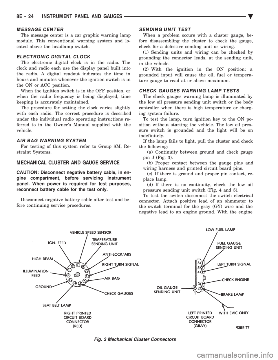
pin J (Fig. 3). (b) Proper contact between the gauge pins and
wiring harness and printed circuit board pins. (c) If there is ground and proper pin contact, re-
place lamp. (d) If there is no continuity, check the low oil
pressure sending unit switch (Fig. 4 and 5).
To test the switch disconnect the switch electrical
connector. Attach positive lead of an ohmmeter to
the switch terminal for the gray (GY) wire and the
negative lead to an engine ground. With the engine
Fig. 3 Mechanical Cluster Connectors
8E - 24 INSTRUMENT PANEL AND GAUGES Ä
Page 535 of 2438
ELECTRONIC DIGITAL CLOCK
The electronic digital clock is in the radio. The
clock and radio each use the display panel built into
the radio. A digital readout indicates the time in
hours and minutes whenever the ignition switch is in
the ON or ACC position. When the ignition switch is in the ON or OFF po-
sition, or when the radio frequency is being dis-
played, time keeping is accurately maintained. The procedure for setting the clock varies slightly
with each radio. The correct procedure is described
under the individual radio operating instructions re-
ferred to in the Owner's manual supplied with the
vehicle.
WARNING LAMPS
The AG & AJ Body instrument clusters have warn-
ing lamps or indicators with the electronic cluster for
six different systems. These include low oil pressure,
check gauges, brake system, air bag, seat belt, mal-
function indicator (check engine) lamp.
CLUSTER AND GAUGE SERVICE AND TESTING
CAUTION: Disconnect negative battery cable, in en-
gine compartment, before servicing instrument
panel. When power is required for test purposes,
reconnect battery cable for test only. Disconnect negative battery cable after test and be-
fore continuing service procedures. It is not necessary to remove instrument cluster
from vehicle for gauge replacement. Gauges must be pulled straight out, when remov-
ing or pins may be damaged.
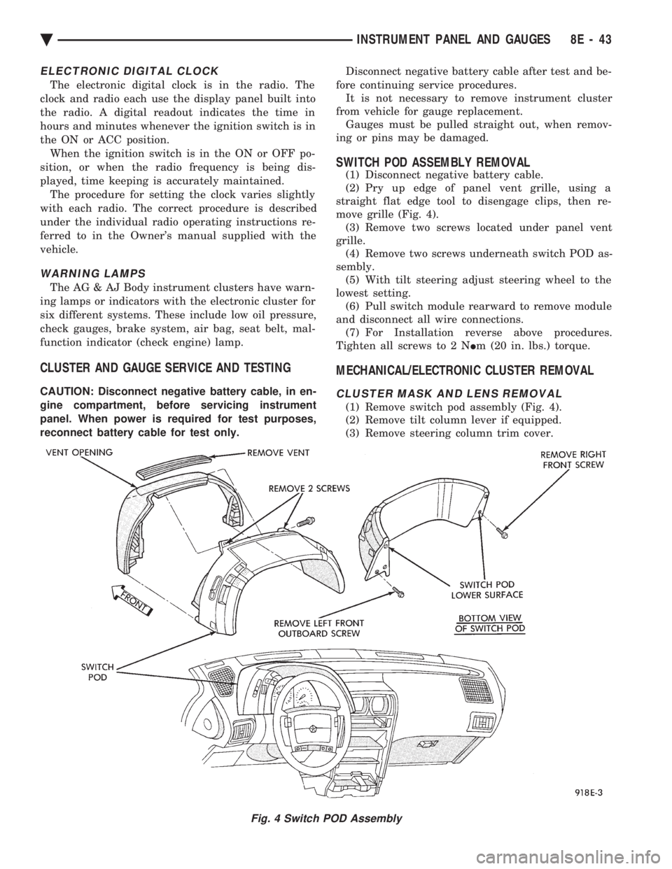
SWITCH POD ASSEMBLY REMOVAL
(1) Disconnect negative battery cable.
(2) Pry up edge of panel vent grille, using a
straight flat edge tool to disengage clips, then re-
move grille (Fig. 4). (3) Remove two screws located under panel vent
grille. (4) Remove two screws underneath switch POD as-
sembly. (5) With tilt steering adjust steering wheel to the
lowest setting. (6) Pull switch module rearward to remove module
and disconnect all wire connections. (7) For Installation reverse above procedures.
Tighten all screws to 2 N Im (20 in. lbs.) torque.
MECHANICAL/ELECTRONIC CLUSTER REMOVAL
CLUSTER MASK AND LENS REMOVAL
(1) Remove switch pod assembly (Fig. 4).
(2) Remove tilt column lever if equipped.
(3) Remove steering column trim cover.
Fig. 4 Switch POD Assembly
Ä INSTRUMENT PANEL AND GAUGES 8E - 43
Page 549 of 2438
(11) Remove two screws from fuse block and lower
fuse block. (12) Remove three screws from hood release and
lower hood release handle. (13) Remove flasher relay from bracket on center
distribution duct. (14) Remove screw from ATC sensor motor assem-
bly and unhook from bracket if equipped. (15) Remove the radio ground screw above flasher
relay mount. (16) Remove center distribution duct screw from
left instrument panel lower brace, then remove four
screws to remove left lower brace.
(17) Remove five nuts on steering column and drop
column, then remove two upper column attaching studs.
(18) Remove two screws and pull out compact disc
player or cubby box, disconnect Co-Axial cable from
compact disc player. (19) Remove Electronic Vehicle Information Center
(E.V.I.C.) or Traveler from vehicle. (20) Remove radio.
(21) Remove A.T.C., A/C or heater controls. (22) Squeeze latches on side of Rear Window defog-
ger switch and remove. (23) Snap off cluster lower trim bezel, switch pod
vent grille, speaker grilles and defroster grilles. (24) Remove switch pod assembly.
(25) Remove cluster assembly.
(26) Remove dash speakers.
(27) Snap out bezel with or without message center
and disconnect wiring. (28) Open glovebox door, squeeze sides and roll
glovebox completely open. Remove glovebox light
switch, and disconnect wires. (29) Loosen right cowl side pivot bolt through
glovebox opening then close glovebox. (30) Loosen left cowl side pivot.
(31) Remove four screw attachments at top of in-
strument panel and roll panel out. (32) Pull wiring, antenna cable, A/C cable and vac-
uum lines out of instrument panel. Disconnect demis-
ter hose and remove instrument panel with ducts
attached. (33) Transfer ducts and brackets onto new panel.
(34) For instrument panel roll up, reverse
above procedures.
INTERIOR LAMP REMOVAL
The Dome, Floor Console and Door Lamps operate
when the doors are open or headlamp switch is
placed in courtesy position.
DOME LAMP
(1) Pry either the forward or rearward edge of the
dome lamp to free it from retaining bracket. (2) Pry either the forward or rearward edge of the
lens away from the bezel and replace lamp. (3) For installation reverse above procedures.
FRONT HEADER READING LAMP
Pull lamp from headliner. Disconnect wiring and
replace lamp.
FLOOR CONSOLE LAMP
Pry along top edge of lamp and pivot lamp out of
floor console, the lens does not remove. Remove lamp
and twist out lamp socket. Replace lamp.
DOOR LAMPS
Pry along bottom edge of lamp and pivot lamp out
of door trim panel, the lens does not remove. Remove
lamp and twist out lamp socket. Replace lamp.
DOOR REFLECTORS
Pry reflector away from the door trim panel, and
replace.
TRUNK LAMP
Remove lens by prying lens out of trunk trim panel
and replace bulb.
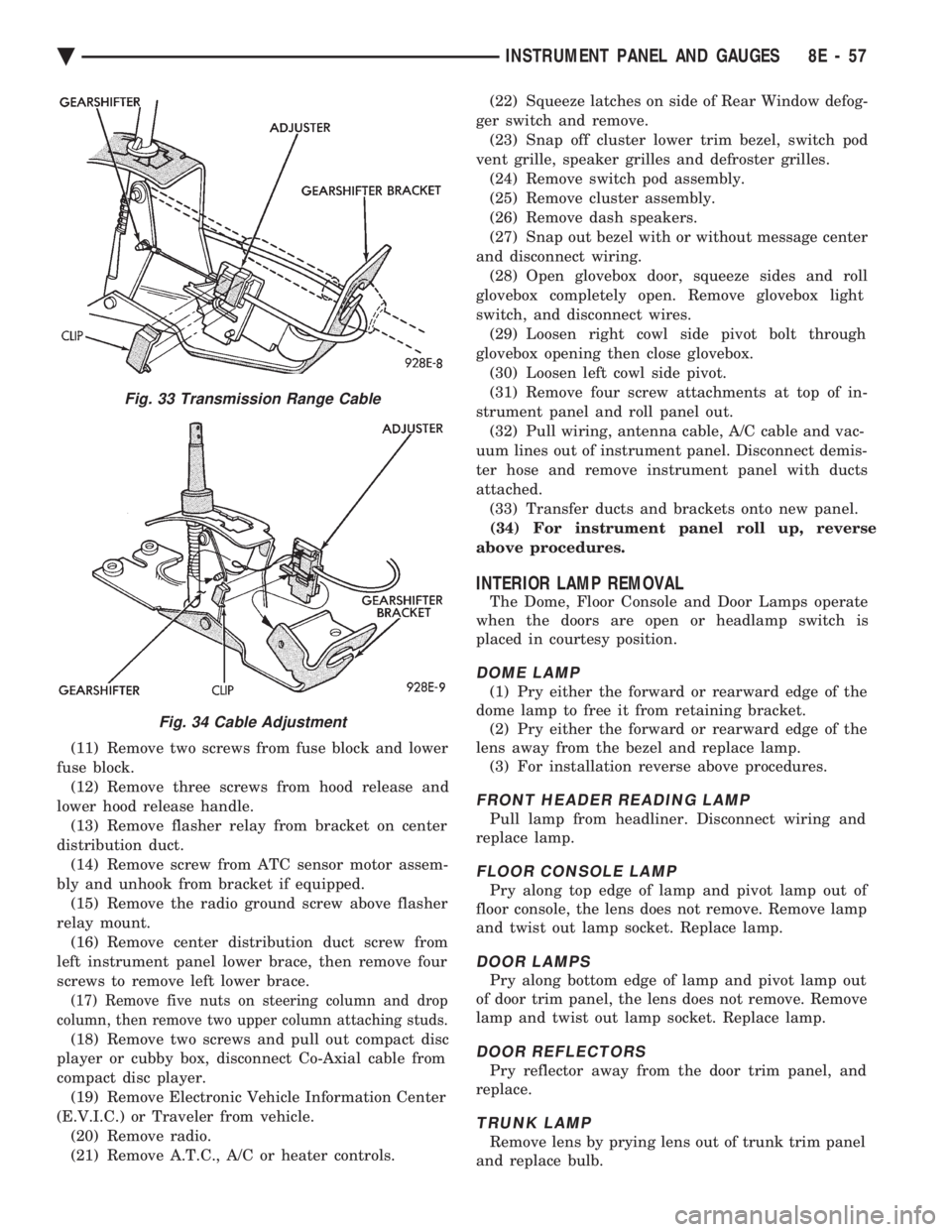
Fig. 33 Transmission Range Cable
Fig. 34 Cable Adjustment
Ä INSTRUMENT PANEL AND GAUGES 8E - 57
Page 550 of 2438
AP BODY INDEX
page page
Cluster and Gauge Service and Testing ....... 58
Gauges ................................ 61
General Information ....................... 58 Instrument Panel Replacement
.............. 72
Interior Lamp Replacement ................. 73
Switch and Panel Component Service ......... 67
GENERAL INFORMATION
INSTRUMENT CLUSTER
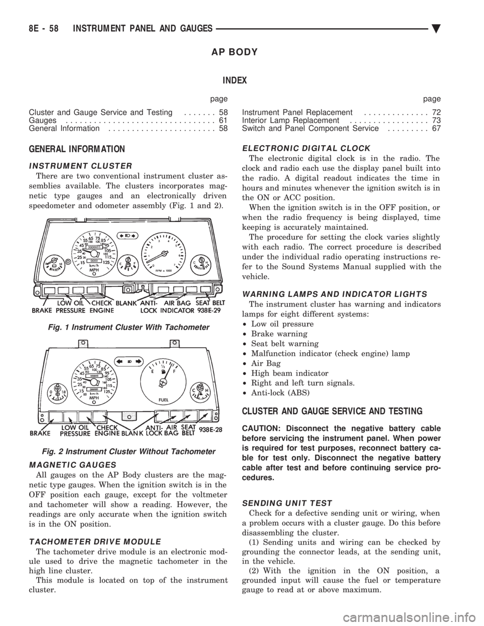
There are two conventional instrument cluster as-
semblies available. The clusters incorporates mag-
netic type gauges and an electronically driven
speedometer and odometer assembly (Fig. 1 and 2).
MAGNETIC GAUGES
All gauges on the AP Body clusters are the mag-
netic type gauges. When the ignition switch is in the
OFF position each gauge, except for the voltmeter
and tachometer will show a reading. However, the
readings are only accurate when the ignition switch
is in the ON position.
TACHOMETER DRIVE MODULE
The tachometer drive module is an electronic mod-
ule used to drive the magnetic tachometer in the
high line cluster. This module is located on top of the instrument
cluster.
ELECTRONIC DIGITAL CLOCK
The electronic digital clock is in the radio. The
clock and radio each use the display panel built into
the radio. A digital readout indicates the time in
hours and minutes whenever the ignition switch is in
the ON or ACC position. When the ignition switch is in the OFF position, or
when the radio frequency is being displayed, time
keeping is accurately maintained. The procedure for setting the clock varies slightly
with each radio. The correct procedure is described
under the individual radio operating instructions re-
fer to the Sound Systems Manual supplied with the
vehicle.
WARNING LAMPS AND INDICATOR LIGHTS
The instrument cluster has warning and indicators
lamps for eight different systems:
² Low oil pressure
² Brake warning
² Seat belt warning
² Malfunction indicator (check engine) lamp
² Air Bag
² High beam indicator
² Right and left turn signals.
² Anti-lock (ABS)
CLUSTER AND GAUGE SERVICE AND TESTING
CAUTION: Disconnect the negative battery cable
before servicing the instrument panel. When power
is required for test purposes, reconnect battery ca-
ble for test only. Disconnect the negative battery
cable after test and before continuing service pro-
cedures.
SENDING UNIT TEST
Check for a defective sending unit or wiring, when
a problem occurs with a cluster gauge. Do this before
disassembling the cluster. (1) Sending units and wiring can be checked by
grounding the connector leads, at the sending unit,
in the vehicle. (2) With the ignition in the ON position, a
grounded input will cause the fuel or temperature
gauge to read at or above maximum.
Fig. 1 Instrument Cluster With Tachometer
Fig. 2 Instrument Cluster Without Tachometer
8E - 58 INSTRUMENT PANEL AND GAUGES Ä
Page 567 of 2438
AUDIO SYSTEM
CONTENTS
page page
ANTENNAS ............................ 20
COMPACT DISC PLAYER ................. 30 RADIOS
................................ 1
SPEAKERS ............................ 24
RADIOS INDEX
page page
Audio Diagnostic Test Procedures ............. 1
Description .............................. 1
Interference Elimination ..................... 1
Radio Removal AP Body Replacement ........ 19 Radio RemovalÐAA Body
.................. 18
Radio RemovalÐAC and AY Bodies .......... 18
Radio RemovalÐAG and AJ Bodies .......... 18
DESCRIPTION
For operation of the factory installed standard and
optional radios and the optional compact disc player,
refer to the Sound Systems Operating Instructions
Manual supplied with the vehicle. All vehicles are equipped with an Ignition-Off
Draw Connector which, is used when the vehicles are
originally shipped from the factory. This connector
which, is located near the battery, helps to prevent
battery discharge during storage. For specific connec-
tor type and location, refer to Group 8W, Wiring Di-
agrams. This connector is included in the radio memory cir-
cuitry and should be checked if the memory of time
or radio station programming is inoperative.
INTERFERENCE ELIMINATION
Some components are used on vehicles equipped
with a radio capacitor, to suppress radio frequency
interference/static. Capacitors are mounted in various locations, on the
generator either internal or external, internal to the
instrument cluster, and internal to the windshield
wiper motor. Ground straps are mounted from radio chassis to
instrument panel support structure, engine to cowl,
across engine mount on right hand side. On vehicles
with air conditioning there is a strap from evapora-
tor valve to cowl. These ground straps should be se-
curely tightened to assure good metal to metal
contact. Ground straps conduct very small high fre-
quency electrical signals to ground and require clean
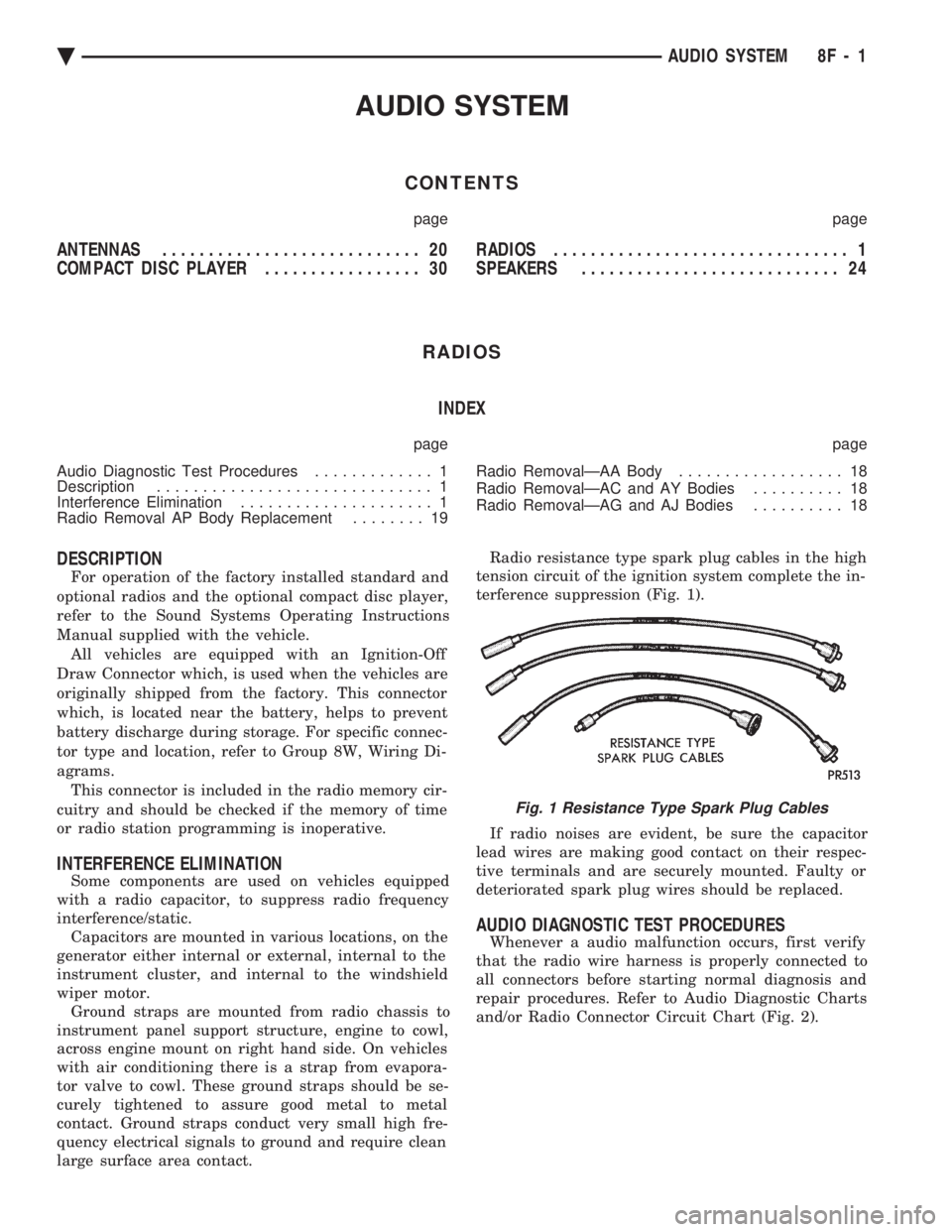
large surface area contact. Radio resistance type spark plug cables in the high
tension circuit of the ignition system complete the in-
terference suppression (Fig. 1).
If radio noises are evident, be sure the capacitor
lead wires are making good contact on their respec-
tive terminals and are securely mounted. Faulty or
deteriorated spark plug wires should be replaced.
AUDIO DIAGNOSTIC TEST PROCEDURES
Whenever a audio malfunction occurs, first verify
that the radio wire harness is properly connected to
all connectors before starting normal diagnosis and
repair procedures. Refer to Audio Diagnostic Charts
and/or Radio Connector Circuit Chart (Fig. 2).
Fig. 1 Resistance Type Spark Plug Cables
Ä AUDIO SYSTEM 8F - 1
Page 583 of 2438
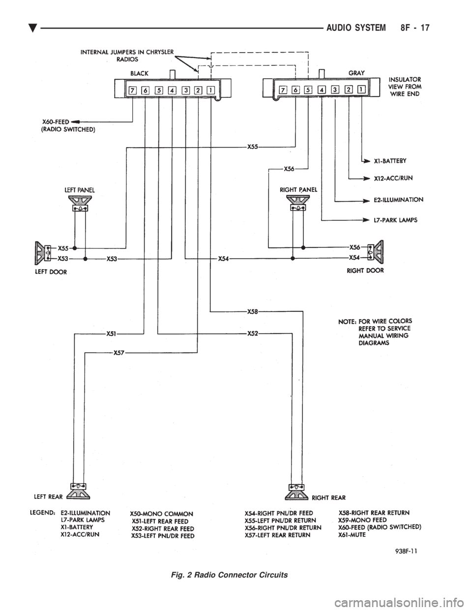
Fig. 2 Radio Connector Circuits
Ä AUDIO SYSTEM 8F - 17
Page 584 of 2438
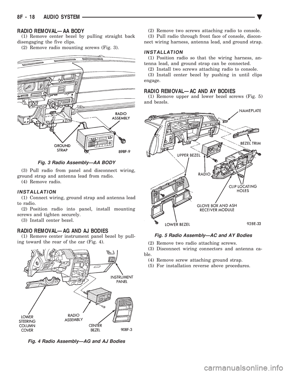
RADIO REMOVALÐAA BODY
(1) Remove center bezel by pulling straight back
disengaging the five clips. (2) Remove radio mounting screws (Fig. 3).
(3) Pull radio from panel and disconnect wiring,
ground strap and antenna lead from radio. (4) Remove radio.
INSTALLATION
(1) Connect wiring, ground strap and antenna lead
to radio. (2) Position radio into panel, install mounting
screws and tighten securely. (3) Install center bezel.
RADIO REMOVALÐAG AND AJ BODIES
(1) Remove center instrument panel bezel by pull-
ing toward the rear of the car (Fig. 4). (2) Remove two screws attaching radio to console.
(3) Pull radio through front face of console, discon-
nect wiring harness, antenna lead, and ground strap.
INSTALLATION
(1) Position radio so that the wiring harness, an-
tenna lead, and ground strap can be connected. (2) Install two screws attaching radio to console.
(3) Install center bezel by pushing in until clips
engage.
RADIO REMOVALÐAC AND AY BODIES
(1) Remove upper and lower bezel screws (Fig. 5)
and bezels.
(2) Remove two radio attaching screws.
(3) Disconnect wiring connectors and antenna ca-
ble. (4) Remove screw attaching ground strap.
(5) For installation reverse above procedures.
Fig. 3 Radio AssemblyÐAA BODY
Fig. 4 Radio AssemblyÐAG and AJ Bodies
Fig. 5 Radio AssemblyÐAC and AY Bodies
8F - 18 AUDIO SYSTEM Ä