radio CHEVROLET DYNASTY 1993 Owner's Manual
[x] Cancel search | Manufacturer: CHEVROLET, Model Year: 1993, Model line: DYNASTY, Model: CHEVROLET DYNASTY 1993Pages: 2438, PDF Size: 74.98 MB
Page 585 of 2438
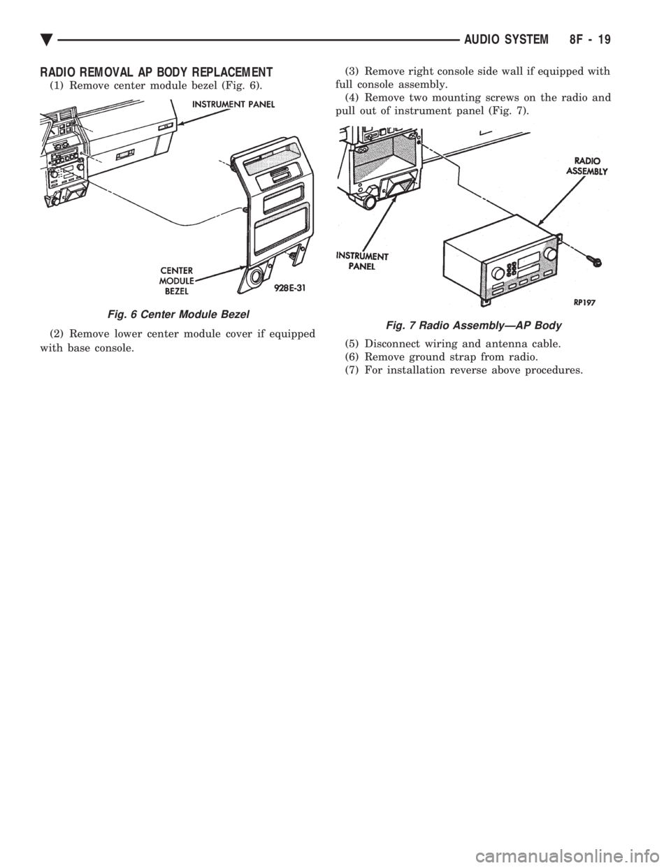
RADIO REMOVAL AP BODY REPLACEMENT
(1) Remove center module bezel (Fig. 6).
(2) Remove lower center module cover if equipped
with base console. (3) Remove right console side wall if equipped with
full console assembly. (4) Remove two mounting screws on the radio and
pull out of instrument panel (Fig. 7).
(5) Disconnect wiring and antenna cable.
(6) Remove ground strap from radio.
(7) For installation reverse above procedures.
Fig. 6 Center Module Bezel
Fig. 7 Radio AssemblyÐAP Body
Ä AUDIO SYSTEM 8F - 19
Page 586 of 2438
ANTENNAS INDEX
page page
Manual Antennas ........................ 20
Power Antenna .......................... 21 Power Antenna Mast
...................... 23
MANUAL ANTENNAS
TESTING
Antenna performance may be tested by substitut-
ing a known good antenna. It is also possible to
check short or open circuits with an ohmmeter or
continuity light once the antenna cable is discon-
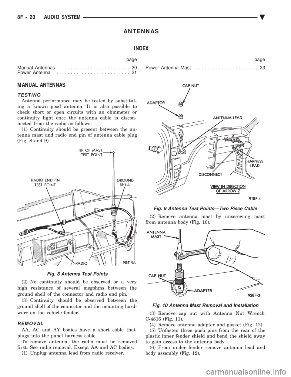
nected from the radio as follows: (1) Continuity should be present between the an-
tenna mast and radio end pin of antenna cable plug
(Fig. 8 and 9).
(2) No continuity should be observed or a very
high resistance of several megohms between the
ground shell of the connector and radio end pin. (3) Continuity should be observed between the
ground shell of the connector and the mounting hard-
ware on the vehicle fender.
REMOVAL
AA, AC and AY bodies have a short cable that
plugs into the panel harness cable. To remove antenna, the radio must be removed
first. See radio removal. Except AA and AC bodies. (1) Unplug antenna lead from radio receiver. (2) Remove antenna mast by unscrewing mast
from antenna body (Fig. 10).
(3) Remove cap nut with Antenna Nut Wrench
C-4816 (Fig. 11). (4) Remove antenna adapter and gasket (Fig. 12).
(5) Unfasten three push pins from the rear of the
plastic inner fender shield and bend the shield away
to gain access to the antenna body. (6) From under fender remove antenna lead and
body assembly (Fig. 12).
Fig. 8 Antenna Test Points
Fig. 9 Antenna Test PointsÐTwo Piece Cable
Fig. 10 Antenna Mast Removal and Installation
8F - 20 AUDIO SYSTEM Ä
Page 587 of 2438
INSTALLATION
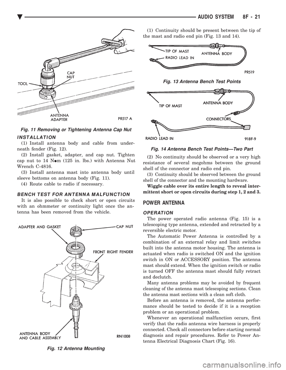
(1) Install antenna body and cable from under-
neath fender (Fig. 12). (2) Install gasket, adapter, and cap nut. Tighten
cap nut to 14 N Im (125 in. lbs.) with Antenna Nut
Wrench C-4816. (3) Install antenna mast into antenna body until
sleeve bottoms on antenna body (Fig. 11). (4) Route cable to radio if necessary.
BENCH TEST FOR ANTENNA MALFUNCTION
It is also possible to check short or open circuits
with an ohmmeter or continuity light once the an-
tenna has been removed from the vehicle. (1) Continuity should be present between the tip of
the mast and radio end pin (Fig. 13 and 14).
(2) No continuity should be observed or a very high
resistance of several megohms between the ground
shell of the connector and radio end pin.
(3) Continuity should be observed between the ground
shell of the connector and the mounting hardware.
Wiggle cable over its entire length to reveal inter-
mittent short or open circuits during step 1, 2 and 3.
POWER ANTENNA
OPERATION
The power operated radio antenna (Fig. 15) is a
telescoping type antenna, extended and retracted by a
reversible electric motor. The Automatic Power Antenna is controlled by a
combination of an external relay and limit switches
built into the antenna motor housing. The antenna is
actuated when radio is switched ON and the ignition
switch in ON or ACCESSORY position. The antenna
mast should extend. When the ignition switch or radio
is turned OFF the antenna mast should fully retract
and declutch.
Many antenna problems may be avoided by frequent
cleaning of the antenna mast telescoping sections. Clean
the antenna mast sections with a clean soft cloth.
Before an antenna is removed, the antenna perfor-
mance should be tested to decide if it is a reception
problem or an operational problem. Whenever an operational malfunction occurs, first
verify that the radio antenna wire harness is properly
connected. Check all connectors before starting normal
diagnosis and repair procedures. Refer to Power An-
tenna Electrical Diagnosis Chart (Fig. 16).
Fig. 12 Antenna Mounting
Fig. 11 Removing or Tightening Antenna Cap Nut
Fig. 13 Antenna Bench Test Points
Fig. 14 Antenna Bench Test PointsÐTwo Part
Ä AUDIO SYSTEM 8F - 21
Page 589 of 2438
(8) Upon establishing that the fault is in the an-
tenna assembly, it may be traced to one or more of
the following conditions: (a) Broken lead-in wire or shielding.
(b) Grounded lead-in wire or mast assembly.
(c) Moisture in support tube or lead-in assembly.
(d) Poor connection at antenna lead-in assembly
or shielding ground.
REMOVAL
(1) Disconnect battery negative cable.
(2) Remove the right front fender splash shield fas-
teners and pull shield away from the wheel housing.
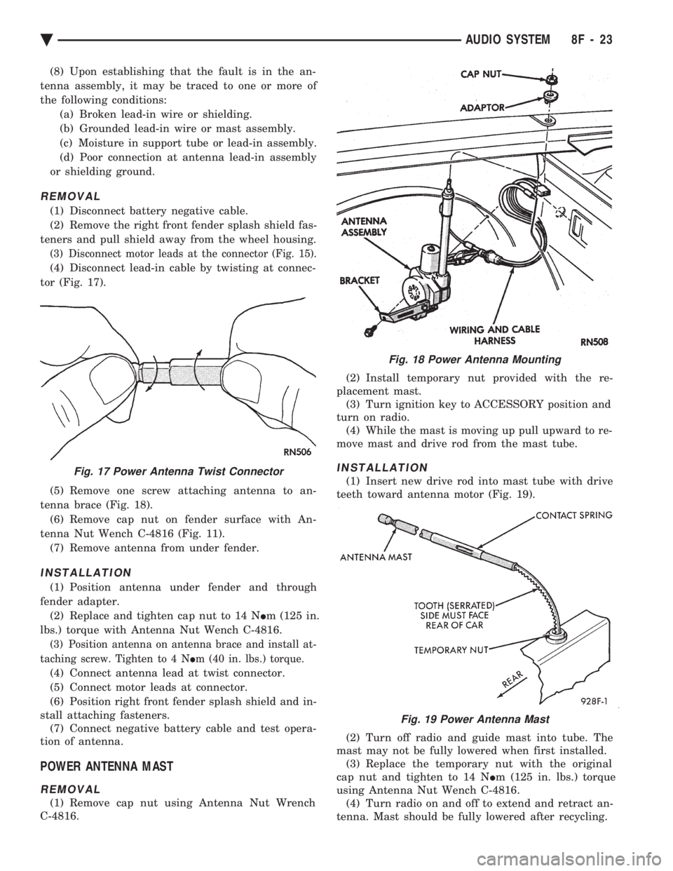
(3) Disconnect motor leads at the connector (Fig. 15).
(4) Disconnect lead-in cable by twisting at connec-
tor (Fig. 17).
(5) Remove one screw attaching antenna to an-
tenna brace (Fig. 18). (6) Remove cap nut on fender surface with An-
tenna Nut Wench C-4816 (Fig. 11). (7) Remove antenna from under fender.
INSTALLATION
(1) Position antenna under fender and through
fender adapter. (2) Replace and tighten cap nut to 14 N Im (125 in.
lbs.) torque with Antenna Nut Wench C-4816.
(3) Position antenna on antenna brace and install at-
taching screw. Tighten to 4 N Im (40 in. lbs.) torque.
(4) Connect antenna lead at twist connector.
(5) Connect motor leads at connector.
(6) Position right front fender splash shield and in-
stall attaching fasteners. (7) Connect negative battery cable and test opera-
tion of antenna.
POWER ANTENNA MAST
REMOVAL
(1) Remove cap nut using Antenna Nut Wrench
C-4816. (2) Install temporary nut provided with the re-
placement mast. (3) Turn ignition key to ACCESSORY position and
turn on radio. (4) While the mast is moving up pull upward to re-
move mast and drive rod from the mast tube.
INSTALLATION
(1) Insert new drive rod into mast tube with drive
teeth toward antenna motor (Fig. 19).
(2) Turn off radio and guide mast into tube. The
mast may not be fully lowered when first installed. (3) Replace the temporary nut with the original
cap nut and tighten to 14 N Im (125 in. lbs.) torque
using Antenna Nut Wench C-4816. (4) Turn radio on and off to extend and retract an-
tenna. Mast should be fully lowered after recycling.
Fig. 18 Power Antenna Mounting
Fig. 17 Power Antenna Twist Connector
Fig. 19 Power Antenna Mast
Ä AUDIO SYSTEM 8F - 23
Page 594 of 2438
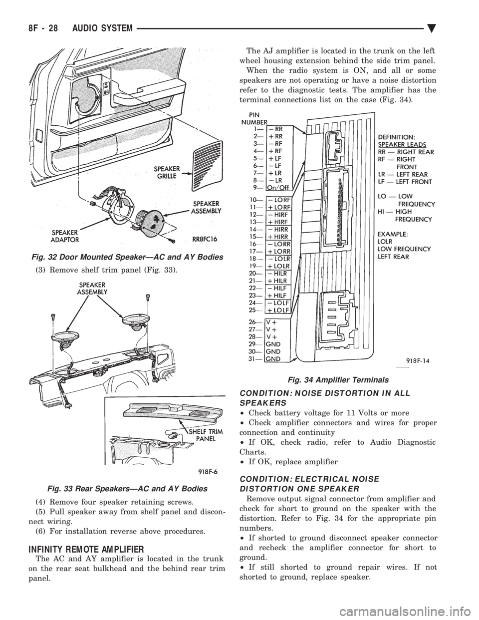
(3) Remove shelf trim panel (Fig. 33).
(4) Remove four speaker retaining screws.
(5) Pull speaker away from shelf panel and discon-
nect wiring. (6) For installation reverse above procedures.
INFINITY REMOTE AMPLIFIER
The AC and AY amplifier is located in the trunk
on the rear seat bulkhead and the behind rear trim
panel. The AJ amplifier is located in the trunk on the left
wheel housing extension behind the side trim panel. When the radio system is ON, and all or some
speakers are not operating or have a noise distortion
refer to the diagnostic tests. The amplifier has the
terminal connections list on the case (Fig. 34).
CONDITION: NOISE DISTORTION IN ALL SPEAKERS
² Check battery voltage for 11 Volts or more
² Check amplifier connectors and wires for proper
connection and continuity
² If OK, check radio, refer to Audio Diagnostic
Charts.
² If OK, replace amplifier
CONDITION: ELECTRICAL NOISE
DISTORTION ONE SPEAKER
Remove output signal connector from amplifier and
check for short to ground on the speaker with the
distortion. Refer to Fig. 34 for the appropriate pin
numbers.
² If shorted to ground disconnect speaker connector
and recheck the amplifier connector for short to
ground.
² If still shorted to ground repair wires. If not
shorted to ground, replace speaker.
Fig. 32 Door Mounted SpeakerÐAC and AY Bodies
Fig. 33 Rear SpeakersÐAC and AY Bodies
Fig. 34 Amplifier Terminals
8F - 28 AUDIO SYSTEM Ä
Page 595 of 2438
² If no short to ground at connector, check speaker
resistance at amplifier connector for an reading of
three to five ohms.
² If resistance is OK, refer to Radio Diagnosis. If ra-
dio checks OK, replace amplifier.
² If resistance is less than three ohms check
speaker. Check across the speaker connector if less
than three ohms replace speaker. If resistance is OK
repair wires
CONDITION: MECHANICAL NOISE DISTORTION
² Check trim for loose parts and speaker attach-
ments for buzzes
² Remove speaker still connected and listen for dis-
tortion. Distortion replace speaker.
CONDITION: ONE SPEAKER NON-OPERATIVE
² Remove output signal connector from amplifier
and check for three to five ohms resistance to the
non-operative speaker. Refer to Fig. 34 for the appro-
priate pin numbers.
² If resistance is less than three ohms, test speaker
for resistance.
² If OK repair wire. If not replace speaker.
CONDITION: ALL SPEAKERS NON-OPERATIVE
²Check radio for being ON, are the display lights
on
² Radio not ON, refer to Radio Diagnosis
² Check Amplifier Connectors and wires for proper
connection
² Check pin 9 and pin 27 for battery voltage
² If voltage OK replace amplifier ²
If pin 27 has battery voltage and pin 9 has 0 volt-
age. Refer to Power Antenna Diagnosis and test volt-
age at antenna relay.
² If pin 9 has battery voltage and pin 27 has 0 volt-
age. Check pin 27 for short to ground.
² If shorted to ground repair wire
² If no short to ground check fuse cavity number 16
for blown fuse.
² If fuse blows again replace amplifier
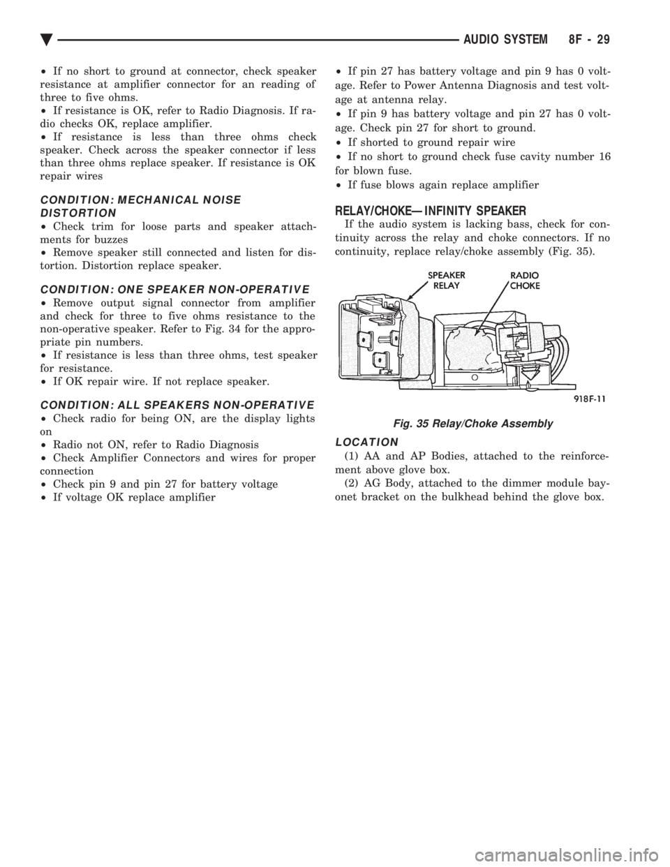
RELAY/CHOKEÐINFINITY SPEAKER
If the audio system is lacking bass, check for con-
tinuity across the relay and choke connectors. If no
continuity, replace relay/choke assembly (Fig. 35).
LOCATION
(1) AA and AP Bodies, attached to the reinforce-
ment above glove box. (2) AG Body, attached to the dimmer module bay-
onet bracket on the bulkhead behind the glove box.
Fig. 35 Relay/Choke Assembly
Ä AUDIO SYSTEM 8F - 29
Page 596 of 2438
COMPACT DISC PLAYER
WARNING: USE OF THE CONTROLS, ADJUST-
MENTS, OR SERVICE PROCEDURES NOT SPECI-
FIED HERE OR IN THE OWNER MANUAL MAY
RESULT IN HAZARDOUS RADIATION EXPOSURE.
REPAIR PROCEDURES SHOULD ONLY BE PER-
FORMED BY A TRAINED TECHNICIAN.
DIAGNOSIS TEST
Power to the compact disc player is supplied by the
radio through the CD interface cable. The compact
disc player will only work with the radio system
turned ON. When a compact disc is inserted with the
label side facing up, the disc is automatically loaded
and will begin to play. The CD player may eject the disc with a display of
E under the following conditions:
² The surface of the disc is dirty or wet
² The disc was inserted with the label side facing
down
² The disc is defective
² The CD player may skip or mute while playing a
disc under severe vibration conditions example pot
holes, railroad tracks, etc.
² If the CD player becomes too hot at temperatures
above 60ÉC (140 ÉF) the CD player will shut down
with a display of HOT until it cools down. Refer to
the Audio Diagnostic Charts.
COMPACT DISC PLAYER REPLACEMENT
With intergral compact disc player refer to Radio
Removal.
AJ BODY
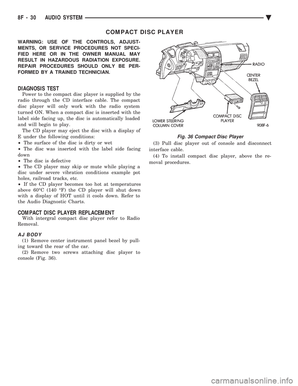
(1) Remove center instrument panel bezel by pull-
ing toward the rear of the car. (2) Remove two screws attaching disc player to
console (Fig. 36). (3) Pull disc player out of console and disconnect
interface cable. (4) To install compact disc player, above the re-
moval procedures.
Fig. 36 Compact Disc Player
8F - 30 AUDIO SYSTEM Ä
Page 681 of 2438
AA .............................................................................74
Low Fuel
AA ...........................................................................103
AP ............................................................................161
AC, AY...............................................................PC194
AG, AJ ............................................................5269245
Low Washer Fluid
AA, AC, AY .............................................................74
AP ............................................................................161
AG, AJ ............................................................4437661
Oil Pressure
All .......................................................................PC194
Trunk Open
AA, AC, AY .............................................................74
AP ............................................................................161
AG, AJ ............................................................4437661
Theft Alarm Set
AC, AY....................................................................168
AG, AJ ............................................................4437661
Turn Signal (MIC)
AA ...........................................................................103
AC, AG, AJ, AP, AY .......................................PC194
Turn Signal (EIC)
AA, AY ..............................................................PC194
Seat Belt (MIC)
AA ...........................................................................103
AC, AG, AJ, AP, AY .......................................PC194
Seat Belt (EIC)
AA, AY ..............................................................PC194
AJ ............................................................................103
DIMMER CONTROLLED LAMPS
Service procedures for most of the lamps in the in-
strument panel, Instrument cluster and switches are
located in Group 8E, Instrument Panel and Gauges. A/C Heater Control
All ..............................................................................37
Automatic Temperature Control
All ....................................................................4437661
Column Gearshift Indicator
AA, AC, AY ...........................................................161
Console Gearshift Indicator
AP ............................................................................194
AA, AG, AJ ............................................................161
Fog Lamp Switch Symbol
AG ......................................................................PC194
Headlamp Dimmer Switch
AG, AJ ......................................................................37
Headlamp Switch Symbol
AC, AY....................................................................161
AG, AJ ......................................................................37
Heater Control
All ............................................................................158
EVIC
AJ...........................................................................ASC
Instrument Cluster (MIC)
All .......................................................................PC194
Instrument Cluster (EIC) AA, AY .....................................................................74
Message Center
AA, AC, AY .............................................................74
AP ............................................................................161
Navigator/Travel Companion
AA, AJ ......................................................................74
Radio
All ..........................................................................ASC
Rear Defogger Switch
Not Serviceable, Replace Switch
Rear Wiper Switch
AG .............................................................................37
Theft Alarm
AC, AY....................................................................161
Top Lift Switch
AJ ....................................................................5268053
Travel Computer
All ..........................................................................ASC
Turbo Gauge
AP ............................................................................161
Windshield Wiper Switch
AG, AJ ......................................................................37
NON-DIMMING LAMPS
Service procedures for most of the lamps in the fol-
lowing list can be found in Group 23, Body. Some
components have lamps that can only be serviced by
a Authorized Service Center (ASC) after the compo-
nent is removed from the vehicle. Contact local
dealer for location of nearest ASC. Ash Receiver
AA .............................................................................74
AC, AP, AY ............................................................161
AG, AJ ......................................................................37
Center Console Rear
AJ ............................................................................906
Cigar Lighter
AA, AP ....................................................................161
Courtesy
AA, AC, AY-S .....................................................214-2
AJ ............................................................................906
AY-P.....................................................................212-2
Dome
ALL ......................................................................211-2
Engine Compartment
All ............................................................................105
Glove Compartment
All ..........................................................................1891
Ignition Lock
All ..............................................................................37
Inside Rear View Mirror
AJ ............................................................................168
Overhead Console
AA ...........................................................................912
AC, AY....................................................................906
AG, AJ, AP .........................................................212-2
Reading Lamp Front
All ............................................................................906
Ä LAMPS 8L - 39
Page 695 of 2438
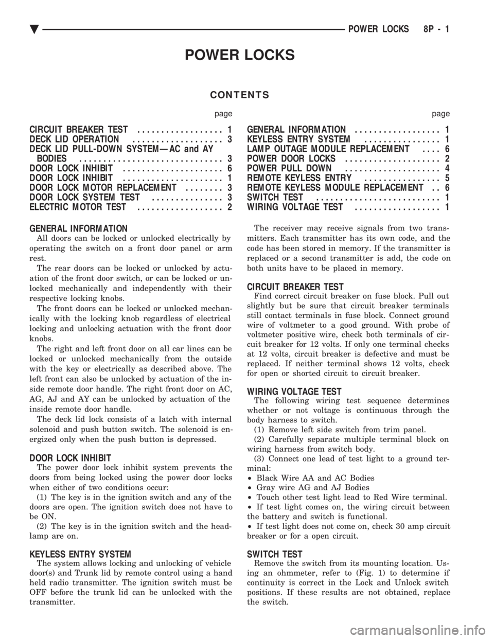
POWER LOCKS
CONTENTS
page page
CIRCUIT BREAKER TEST .................. 1
DECK LID OPERATION ................... 3
DECK LID PULL-DOWN SYSTEMÐAC and AY BODIES .............................. 3
DOOR LOCK INHIBIT ..................... 6
DOOR LOCK INHIBIT ..................... 1
DOOR LOCK MOTOR REPLACEMENT ........ 3
DOOR LOCK SYSTEM TEST ............... 3
ELECTRIC MOTOR TEST .................. 2 GENERAL INFORMATION
.................. 1
KEYLESS ENTRY SYSTEM ................ 1
LAMP OUTAGE MODULE REPLACEMENT .... 6
POWER DOOR LOCKS .................... 2
POWER PULL DOWN .................... 4
REMOTE KEYLESS ENTRY ................ 5
REMOTE KEYLESS MODULE REPLACEMENT . . 6
SWITCH TEST .......................... 1
WIRING VOLTAGE TEST .................. 1
GENERAL INFORMATION
All doors can be locked or unlocked electrically by
operating the switch on a front door panel or arm
rest. The rear doors can be locked or unlocked by actu-
ation of the front door switch, or can be locked or un-
locked mechanically and independently with their
respective locking knobs. The front doors can be locked or unlocked mechan-
ically with the locking knob regardless of electrical
locking and unlocking actuation with the front door
knobs. The right and left front door on all car lines can be
locked or unlocked mechanically from the outside
with the key or electrically as described above. The
left front can also be unlocked by actuation of the in-
side remote door handle. The right front door on AC,
AG, AJ and AY can be unlocked by actuation of the
inside remote door handle. The deck lid lock consists of a latch with internal
solenoid and push button switch. The solenoid is en-
ergized only when the push button is depressed.
DOOR LOCK INHIBIT
The power door lock inhibit system prevents the
doors from being locked using the power door locks
when either of two conditions occur: (1) The key is in the ignition switch and any of the
doors are open. The ignition switch does not have to
be ON. (2) The key is in the ignition switch and the head-
lamp are on.
KEYLESS ENTRY SYSTEM
The system allows locking and unlocking of vehicle
door(s) and Trunk lid by remote control using a hand
held radio transmitter. The ignition switch must be
OFF before the trunk lid can be unlocked with the
transmitter. The receiver may receive signals from two trans-
mitters. Each transmitter has its own code, and the
code has been stored in memory. If the transmitter is
replaced or a second transmitter is add, the code on
both units have to be placed in memory.
CIRCUIT BREAKER TEST
Find correct circuit breaker on fuse block. Pull out
slightly but be sure that circuit breaker terminals
still contact terminals in fuse block. Connect ground
wire of voltmeter to a good ground. With probe of
voltmeter positive wire, check both terminals of cir-
cuit breaker for 12 volts. If only one terminal checks
at 12 volts, circuit breaker is defective and must be
replaced. If neither terminal shows 12 volts, check
for open or shorted circuit to circuit breaker.
WIRING VOLTAGE TEST
The following wiring test sequence determines
whether or not voltage is continuous through the
body harness to switch. (1) Remove left side switch from trim panel.
(2) Carefully separate multiple terminal block on
wiring harness from switch body. (3) Connect one lead of test light to a ground ter-
minal:
² Black Wire AA and AC Bodies
² Gray wire AG and AJ Bodies
² Touch other test light lead to Red Wire terminal.
² If test light comes on, the wiring circuit between
the battery and switch is functional.
² If test light does not come on, check 30 amp circuit
breaker or for a open circuit.
SWITCH TEST
Remove the switch from its mounting location. Us-
ing an ohmmeter, refer to (Fig. 1) to determine if
continuity is correct in the Lock and Unlock switch
positions. If these results are not obtained, replace
the switch.
Ä POWER LOCKS 8P - 1
Page 931 of 2438
WIRING DIAGRAMS AA-BODY
INDEX
Wiring Diagram
Name Sheet Number
Airbag System ...............................47
Clockspring ...............................47
Diagnostic Module ..........................47
Interface Grommet ..........................47
Sensor-Left ...............................47
Sensor-Right ..............................47
Squibb ..................................47
Air Conditioning Compressor ...................32, 33
Air Conditioning System (2.5L Engine) ...............71
A/C Cycling Switch ..........................71
Blower Motor ..............................71
Blower Switch .............................71
Control Switch .............................71
Damped Pressure Switch ......................71
Defrost Switch .............................71
Illumination Lamp ...........................71
Resistor .................................71
Air Conditioning System (3.0L Engine) ...............72
A/C Switch ...............................72
Blower Motor ..............................72
Blower Switch .............................72
Control Switch .............................72
Damped Pressure Switch ......................72
Defrost Switch .............................72
High Pressure Switch ........................72
Illumination Lamp ...........................72
Resistor .................................72
Anti-Lock Brake System .................41, 42, 43, 44
ABS Pump Motor Relay .......................41
ABS System Relay ..........................43
ABS Warning Lamp Relay ......................43
Brake Switch ..............................44
Controller ....................... .41, 42, 43, 44
Hydraulic Modulator .........................41
Ignition Switch .............................44
Park Brake Switch ...........................44
Wheel Sensors .............................42
Ash Receiver Lamp ...........................52
Automatic Shut-down Relay .................14, 20, 28
Automatic Transmission Park/Neutral Position and Back-Up Lamp Switch ...............................9
Back-Up Lamp Switch ..........................9
Battery ............................1,5,7,39,40
Blower Motor-A/C ............................71
Blower Motor-Heater ...........................71
Brake Switch ...............................44
Brake Warning Lamp Switch ......................11
Bulkhead Disconnect (50-Way) ................112, 113
Center High Mounted Stop Lamp ..........94, 98, 102, 105
Charging System (2.5L) ........................5,6
Battery ...................................5
Generator .................................6Wiring Diagram
Name Sheet Number
Heated Rear Window Switch .....................5
Charging System (3.0L) ........................7,8
Battery ....................................7
Generator .................................8
Ignition Off-Draw Connector .....................7
Cigar Lighter ................................45
Cigar Lighter Lamp ............................52
Circuit Breaker (30 Amp) Fuseblock Cavity #10 .......67, 82
Circuit Breaker (30 Amp) Fuseblock Cavity #13 . . .2, 66, 67, 86
Clockspring ............................. .47, 59
Cluster Printed Circuit Board .................119, 120
Cluster Printed Circuit Board Connectors .............118
Courtesy Lamps .............................76
Daytime Running Light Module ....................57
Deck Lid Ajar Switch ..........................78
Dimmer Switch-Headlamp .....................1,50
Distributor ......................... .15, 21, 22, 27
EGR Solenoid ...............................24
Electrically Heated Rear Window ...................84
Heated Rear Window .........................84
Switch ..................................84
Timer ...................................84
Electronically Tuned Stereo Radio without Name Brand Speakers ................................87
Electronically Tuned Stereo Radio with Name Brand Speakers ................................89
Speaker Choke .............................89
Speaker Relay .............................89
Electronic Cluster ........................... .121
Engine Coolant Sensor ................... .15, 21, 27
Engine Oil and Temperature Warning System (2.5L) .......39
Engine Oil and Temperature Warning System (3.0L) .......40
Engine Oil Pressure Switch/Sending Unit ...........39, 40
Engine Temperature Sending Unit ................39, 40
Engine Starter System (2.5L Engine & 3.0L ATX) .......9,10
Automatic Transmission Park/Neutral Position Switch .....9
Backup Lamp Switch ..........................9
EMCC Solenoid .............................9
Engine Starter Relay ..........................9
Manual Transmission Back-Up Lamp Switch ...........9
Permanent Magnet Engine Starter Motor .............9
Engine Temperature Sending Unit ................39, 40
Exhaust Gas Recirculation Diagnostic Solenoid ........13, 24
Fan Control System with A/C and Heater System (2.5L) ....32
A/C Compressor ............................32
A/C Compressor Clutch Relay ...................32
A/C High Pressure Switch ......................32
Fan Control Relay ...........................32
Radiator Fan Motor ..........................32
Fan Control System with A/C and Heater System (3.0L) ....33
A/C Conditioning Compressor ...................33
A/C Compressor Clutch Relay ...................33
Ä WIRING DIAGRAMS AA-BODY 8W - 181