heater CHEVROLET DYNASTY 1993 Owner's Manual
[x] Cancel search | Manufacturer: CHEVROLET, Model Year: 1993, Model line: DYNASTY, Model: CHEVROLET DYNASTY 1993Pages: 2438, PDF Size: 74.98 MB
Page 685 of 2438
SERVICE OF DEPLOYED AIR BAG MODULE
After an air bag has been deployed, the air bag
module and clockspring must be replaced because
they cannot be reused. Other air bag system compo-
nents are replaced if damaged.
SCHEDULED MAINTENANCE INSPECTION
Vehicles equipped with a Air Bag System must be
inspected every three years or 30,000 miles / 48,000
Km. The following items should be inspected. (1) Inspect components for damage or deteriora-
tion. (a) If the air bag module housing shows signs of
physical damage or abuse, replace the module. (b) Check that both front impact sensors are
properly installed to the upper crossmember of the
radiator closure panel. Repair as required.
(2) Check the air bag warning lamp for proper op-
eration as follows: (a) Turn ignition switch to the ON position, the
air bag warning lamp should light. If not, test the system using the DRB II and Passive Restraint
System Diagnostic Procedures Manual. Repair as
required.
(b) The air bag warning lamp lights, but fails to go
out after ten seconds. Test the system using the DRB
II and Passive Restraint System Diagnostic Proce-
dures Manual. Repair as required. (c) Erasing of fault codes is not required.
AIR BAG SYSTEM CHECK
WARNING: BEFORE BEGINNING ANY AIR BAG SYS-
TEM CHECK PROCEDURES, REMOVE AND ISOLATE
THE BATTERY NEGATIVE (-) CABLE (GROUND)
FROM THE VEHICLE BATTERY. THIS IS THE ONLY
SURE WAY TO DISABLE THE AIR BAG SYSTEM.
FAILURE TO DO THIS COULD RESULT IN ACCIDEN-
TAL AIR BAG DEPLOYMENT AND POSSIBLE PER-
SONAL INJURY.
WHEN AN UNDEPLOYED AIR BAG ASSEMBLY IS
TO BE REMOVED FROM THE STEERING WHEEL,
DISCONNECT BATTERY GROUND CABLE AND
ISOLATE. ALLOW SYSTEM CAPACITOR TO DIS-
CHARGE FOR TWO MINUTES, THEN BEGIN AIR
BAG REMOVAL. (1) Disconnect the battery negative cable and iso-
late. (2) Remove forward console or cover as necessary.
(3) Connect DRB II to ASDM diagnostic 6-way con-
nector, located at right side of module. (4) Turn the ignition key to ON position. Exit vehicle
with DRB II. Use the latest version of the proper
cartridge. (5) After checking that no one is inside the vehicle,
connect the negative battery cable. (6) Using the DRB II, read and record active fault
data. (7) Read and record any stored faults.
(8) Refer to the Passive Restraint Diagnostic Test
Manual if any faults are found in steps 6 and 7. (9) Erase stored faults if there are no active fault
codes. If problems remain, fault codes will not erase. (10) With the ignition key in the ON position, make
sure no one is in the vehicle. (11) From the passenger side of vehicle, turn the
ignition key to OFF then ON and observe the instru-
ment cluster air bag lamp. It should go on for 6 to 8
seconds, then go out; indicating system is functioning
normally. If air bag warning lamp either fails to light,
blinks on and off or goes on and stays on, there is
a system malfunction. Refer to the Passive Re-
straint Diagnostic Test Manual to diagnose the
problem.
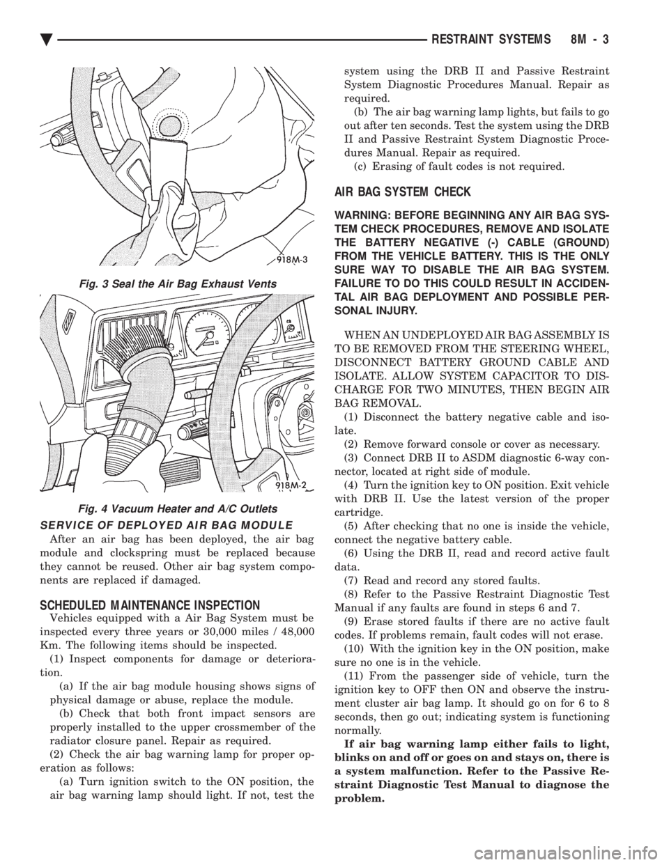
Fig. 3 Seal the Air Bag Exhaust Vents
Fig. 4 Vacuum Heater and A/C Outlets
Ä RESTRAINT SYSTEMS 8M - 3
Page 931 of 2438
WIRING DIAGRAMS AA-BODY
INDEX
Wiring Diagram
Name Sheet Number
Airbag System ...............................47
Clockspring ...............................47
Diagnostic Module ..........................47
Interface Grommet ..........................47
Sensor-Left ...............................47
Sensor-Right ..............................47
Squibb ..................................47
Air Conditioning Compressor ...................32, 33
Air Conditioning System (2.5L Engine) ...............71
A/C Cycling Switch ..........................71
Blower Motor ..............................71
Blower Switch .............................71
Control Switch .............................71
Damped Pressure Switch ......................71
Defrost Switch .............................71
Illumination Lamp ...........................71
Resistor .................................71
Air Conditioning System (3.0L Engine) ...............72
A/C Switch ...............................72
Blower Motor ..............................72
Blower Switch .............................72
Control Switch .............................72
Damped Pressure Switch ......................72
Defrost Switch .............................72
High Pressure Switch ........................72
Illumination Lamp ...........................72
Resistor .................................72
Anti-Lock Brake System .................41, 42, 43, 44
ABS Pump Motor Relay .......................41
ABS System Relay ..........................43
ABS Warning Lamp Relay ......................43
Brake Switch ..............................44
Controller ....................... .41, 42, 43, 44
Hydraulic Modulator .........................41
Ignition Switch .............................44
Park Brake Switch ...........................44
Wheel Sensors .............................42
Ash Receiver Lamp ...........................52
Automatic Shut-down Relay .................14, 20, 28
Automatic Transmission Park/Neutral Position and Back-Up Lamp Switch ...............................9
Back-Up Lamp Switch ..........................9
Battery ............................1,5,7,39,40
Blower Motor-A/C ............................71
Blower Motor-Heater ...........................71
Brake Switch ...............................44
Brake Warning Lamp Switch ......................11
Bulkhead Disconnect (50-Way) ................112, 113
Center High Mounted Stop Lamp ..........94, 98, 102, 105
Charging System (2.5L) ........................5,6
Battery ...................................5
Generator .................................6Wiring Diagram
Name Sheet Number
Heated Rear Window Switch .....................5
Charging System (3.0L) ........................7,8
Battery ....................................7
Generator .................................8
Ignition Off-Draw Connector .....................7
Cigar Lighter ................................45
Cigar Lighter Lamp ............................52
Circuit Breaker (30 Amp) Fuseblock Cavity #10 .......67, 82
Circuit Breaker (30 Amp) Fuseblock Cavity #13 . . .2, 66, 67, 86
Clockspring ............................. .47, 59
Cluster Printed Circuit Board .................119, 120
Cluster Printed Circuit Board Connectors .............118
Courtesy Lamps .............................76
Daytime Running Light Module ....................57
Deck Lid Ajar Switch ..........................78
Dimmer Switch-Headlamp .....................1,50
Distributor ......................... .15, 21, 22, 27
EGR Solenoid ...............................24
Electrically Heated Rear Window ...................84
Heated Rear Window .........................84
Switch ..................................84
Timer ...................................84
Electronically Tuned Stereo Radio without Name Brand Speakers ................................87
Electronically Tuned Stereo Radio with Name Brand Speakers ................................89
Speaker Choke .............................89
Speaker Relay .............................89
Electronic Cluster ........................... .121
Engine Coolant Sensor ................... .15, 21, 27
Engine Oil and Temperature Warning System (2.5L) .......39
Engine Oil and Temperature Warning System (3.0L) .......40
Engine Oil Pressure Switch/Sending Unit ...........39, 40
Engine Temperature Sending Unit ................39, 40
Engine Starter System (2.5L Engine & 3.0L ATX) .......9,10
Automatic Transmission Park/Neutral Position Switch .....9
Backup Lamp Switch ..........................9
EMCC Solenoid .............................9
Engine Starter Relay ..........................9
Manual Transmission Back-Up Lamp Switch ...........9
Permanent Magnet Engine Starter Motor .............9
Engine Temperature Sending Unit ................39, 40
Exhaust Gas Recirculation Diagnostic Solenoid ........13, 24
Fan Control System with A/C and Heater System (2.5L) ....32
A/C Compressor ............................32
A/C Compressor Clutch Relay ...................32
A/C High Pressure Switch ......................32
Fan Control Relay ...........................32
Radiator Fan Motor ..........................32
Fan Control System with A/C and Heater System (3.0L) ....33
A/C Conditioning Compressor ...................33
A/C Compressor Clutch Relay ...................33
Ä WIRING DIAGRAMS AA-BODY 8W - 181
Page 932 of 2438
Wiring Diagram
Name Sheet Number
Fan Control Relay ...........................33
Radiator Fan Motor ..........................33
Fog Lamps ............................. .55, 56
Fog Lamp Relay .............................48
Fog Lamp Switch .............................48
Front End Lighting ........................ .55, 56
Front Left Side Marker Lamp ....................56
Front Right Side Marker Lamp ...................55
Left Aero Hi-Low Beam Headlamp .................56
Left Fog Lamp .............................56
Left Park & Turn Signal Lamp ...................56
Right Aero Hi-Low Beam Headlamp ................55
Right Fog Lamp ............................55
Right Park & Turn Signal Lamp ..................55
Fuel Injection Ignition System (2.5L) .......12, 13, 14, 15, 16
Automatic Shutdown Relay ......................14
Distributor ................................15
Engine Coolant Sensor ........................15
EVAP/Purge Solenoid .........................13
Exhaust Gas Recirculation Diagnostic Solenoid .........13
Heated Oxygen Sensor ........................12
Idle Air Control Motor .........................12
Ignition Coil ...............................14
Injector ..................................16
MAP Sensor ...............................13
Powertrain Control Module ............12, 13, 14, 15, 16
Throttle Position (Sensor) ......................12
Vehicle Speed Senosr .........................15
Fuel Injection Ignition System Flex Fuel (2.5L Engine) ................ .17, 18, 19, 20, 21, 22
Auto Shutdown Relay ........................20
Distributor ...............................22
Engine Coolant Sensor ........................21
EVAP/Purge Solenoid .........................19
Fuel Sensor ...............................17
Heated Oxygen Sensor ........................18
Idle Air Control Motor ........................18
Ignition Coil ...............................20
Injectors .................................17
MAP Sensor ..............................19
Powertrain Control Module (PCM) . . . .17, 18, 19, 20, 21, 22
Throttle Position (Sensor) ......................18
Vehicle Speed Sensor ........................21
Fuel Injection Ignition System (3.0L) ............. .23, 24, 25, 26, 27, 28, 29, 30, 31
Automatic Shutdown Relay .....................28
Distributor ...............................27
Engine Coolant Sensor ........................27
Exhaust Gas Recirculation Diagnostic Solenoid .........24
EVAP/Purge Solenoid .........................23
Heated Oxygen Sensor ........................24
Idle Air Control Motor ........................30
Injectors .................................26
Ignition Coil ...............................29
MAP Sensor ..............................30
Power Steering Pressure Switch ..................25Wiring Diagram
Name Sheet Number
Powertrain Control Module (PCM) .............. .23, 24, 25, 27, 28, 29, 30, 31
Throttle Position (Sensor) ......................24
Vehicle Speed Sensor ........................28
Fuel Pump Motor .............................69
Fuel Pump Relay .............................70
Fuel Tank Electrical Systems ...................69, 70
Fuel Pump Motor ...........................69
Fuel Pump Relays ...........................70
Fuel Tank Level Gauge Sending Unit ...............69
Fuse Application Chart .....................1,2,3,4
Fuses Fuse 1 ..............................4,80,84
Fuse 2 .............4,5,39,40,53,74,80,84,87,89
Fuse 3 ..............................1,95,99
Fuse 4 ..............................1,95,99
Fuse 5 ...............1,49,51,68,71,72,84,87,89
Fuse 6 ..............................2,65,89
Fuse 7 ..............................3,11,59
Fuse 8 ......................3,11,44,45,47,77
Fuse 9 .........................3,11,68,71,72
Fuse 11 ...............3,9,11,16,22,37,47,60,84
Fuse 12 ...............................1,61
Fuse 14 ...............................2,48
Fuse 15 .......................2,45,47,48,106
Fuse 16 ..........................2,44,45,59
Fuse 18 .............................4,11,64
Fuse 19 .............................4,11,61
Fuse 20 ..........................4,11,87,89
Fuseblock Module & Relay Blank ..................107
Glove Box Lamp and Switch ......................54
Hazard Flasher ..............................61
Headlamp Dimmer Switch .....................1,50
Headlamp, Key-in, Seat Belt Chimes .................45
Headlamp Optical Horn Dimmer Switch .............1,50
Headlamp Switch ...........................1,49
Headlamp and Fog Lamp Switch ..............48, 49, 50
Fog Lamp Relay ............................48
Fog Lamp Switch ...........................48
Headlamp Switch ...........................49
Optical Horn & Headlamp Dimmer Switch ............50
Headlamp Switch Controlled Interior Lighting .........51, 52
A/C Lamps ...............................52
Ash Receiver Lamp ..........................52
Cigar Lighter Lamp ..........................52
Heater Lamp ..............................52
Radio Lamp ...............................52
Heated Oxygen Sensor ................... .12, 18, 24
Heated Rear Window ..........................84
Heated Rear Window .........................84
Switch ..................................84
Timer ...................................84
Heater System ...............................68
Bi-level Control Switch ........................68
Blower Motor ..............................68
Blower Slide Control .........................68
Heater Control Switch ........................68
8W - 182 WIRING DIAGRAMS AA-BODY Ä
Page 933 of 2438
Wiring Diagram
Name Sheet Number
Illumination Lamp ...........................68
Resistor .................................68
Horn System ...............................65
Horn (Hi-Note) .............................65
Horn (Lo-Note) ............................65
Horn Relay ...............................65
Horn Switch ..............................65
Hydraulic Modulator (ABS) 41
Ignition Coil .......................... .14, 20, 29
Ignition Off-Draw Connector .....................5,7
Ignition Switch .............................4,11
Brake Warning Lamp Switch ....................11
Park Brake Switch ...........................11
Illuminated Entry .............................58
Illuminated Entry Module ......................58
Left Door Illuminated Entry Switch ................58
Right Door Illuminated Entry Switch ...............58
Illuminated Visor Vanity Mirror ....................73
Injector(s) ........................... .16, 17, 26
Instrument Panel Wiring to Left Body ...............123
Instrument Panel Wiring to Right Body ..............124
Instrument Panel to Multi-Function Switch ............116
Interface Grommet ............................47
Intermittent Wiper System .................... .63, 64
Intermittent Windshield Wiper Motor ...............64
Intermittent Wiper Control Module ................64
Multi-function Switch .........................63
Windshield Washer Low Fluid Level Sensor ...........63
Windshield Washer Pump Motor .................63
Key-In Switch ...............................46
Key-In Warning Chimes .........................45
Lamp Outage Module ........................ .115
Lamps A/C Lamps ...............................52
Ash Receiver Lamp ..........................52
Back-Up Lamps ............ .93, 94, 98, 102, 103, 105
Cargo Lamp ........................ .76, 96, 100
Center High Mounted Stop Lamp ........94, 98, 102, 105
Cigar Lighter Lamp ..........................52
Cluster Lamp ..............................77
Courtesy Lamps ............................76
Dome Lamp ..............................73
Fog Lamp-Left .............................56
Fog Lamp-Right ............................55
Front Reading Lamp .........................75
Glove Box Lamp ............................54
Halo Lamp ...............................54
Headlamp-Left .............................56
Headlamp Out Lamp .........................77
Headlamp-Right ............................55
Heater Lamp ..............................52
Illumination Lamp ..................... .68, 71, 72
Left Front Door Ajar Lamp .....................77
Left Rear Door Ajar Lamp ......................77
Left Side Marker Lamp ........................93
Left Tail/Stop and Turn Lamp ....................93
License Lamp ................... .93, 98, 102, 104Wiring Diagram
Name Sheet Number
Liftgate Ajar Lamp ..........................77
Low Washer Fluid Lamp .......................77
Park/Turn Lamp-Left .........................56
Park/Turn Lamp-Right ........................55
Radio Lamp ...............................52
Reading Lamps ............................75
Right Front Door Ajar Lamp ....................77
Right Rear Door Ajar Lamp .....................77
Seat Belt Warning Lamp .......................45
Side Marker Lamp-Left Front ....................56
Side Marker Lamp-Left Rear ...........93, 98, 102, 103
Side Marker Lamp-Right Front ...................55
Side Marker Lamp-Right Rear ..........94, 98, 102, 105
Stop Lamp Out Lamp ........................77
Tail Lamp Out Lamp .........................77
Tail/Stop Lamp-Left Rear ................... .93, 98
Tail/Stop Lamp-Right Rear .................. .94, 98
Tail/Stop and Turn Lamp-Left Rear .......93, 98, 102, 103
Tail/Stop and Turn Lamp-Right Rear ......94, 98, 102, 105
Transmission Range Indicator Lamp ...............76
Underhood Lamp ........................ .39, 40
Visor Vanity Mirror Lamp ......................73
Left Power Seat System ........................66
Center Switch .............................66
Front Switch ..............................66
Power Seat Motors ..........................66
Rear Switch ...............................66
License Lamp ..................... .93, 98, 102, 104
Lighter-Cigar ................................52
MAP Sensor .......................... .13, 19, 30
Message Center ..............................60
Traveler and Message Center ....................60
Mini Trip Computer ...........................60
Modules Airbag System Diagnostic Module .................47
Daytime Running Light Module ..................57
Illuminated Entry Module ......................58
Intermittent Wiper Control Module ................64
Lamp Outage Module ..................... .95, 99
Motors A/C-Heater Blower Motor ................... .71, 72
Fuel Pump Motor ...........................69
Heater Blower Motor .........................68
Idle Air Control Motor .................. .12, 18, 30
Intermittent Wiper Motor ......................64
Power Door Locks Motors .................. .85, 86
Power Seat Motors ..........................66
Power Window Motors .................... .81, 82
Radiator Fan Motor ...................... .32, 33
Starter Motor ............................9,10
Windshield Washer Pump Motor .................63
Name Brand Speaker Relay ......................89
Optical Horn Headlamp Dimmer Switch .............1,50
Overhead Console, Dome, Reading and Visor Vanity Lamps ..................... .73, 74, 75, 76
Ambient Temperature Sensor ....................75
Cargo Lamp ..............................76
Ä WIRING DIAGRAMS AA-BODY 8W - 183
Page 936 of 2438
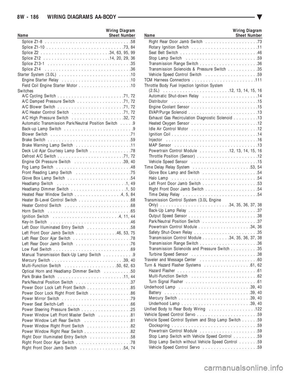
Wiring Diagram
Name Sheet Number
Splice Z1-8 ...............................58
Splice Z1-10 ........................... .73, 84
Splice Z2 ........................ .34, 63, 95, 99
Splice Z12 ....................... .14, 20, 29, 36
Splice Z13-1 ..............................35
Splice Z14 ...............................36
Starter System (3.0L) ..........................10
Engine Starter Relay .........................10
Field Coil Engine Starter Motor ...................10
Switches A/C Cycling Switch ....................... .71, 72
A/C Damped Pressure Switch .................71, 72
A/C Blower Switch ....................... .71, 72
A/C Heater Control Switch .................. .71, 72
A/C High Pressure Switch .................. .32, 72
Automatic Transmission Park/Neutral Position Switch .....9
Back-up Lamp Switch .........................9
Blower Switch .............................71
Brake Switch ..............................59
Brake Warning Lamp Switch ....................11
Deck Lid Ajar Courtesy Lamp Switch ...............78
Defrost A/C Switch ....................... .71, 72
Engine Oil Pressure Switch ..................39, 40
Fog Lamp Switch ...........................48
Front Reading Lamp Switch ....................75
Glove Box Lamp Switch .......................54
Headlamp Switch .........................1,49
Headlamp Dimmer Switch ....................1,50
Heated Rear Window Switch .................4,5,84
Heater Bi-Level Control Switch ...................68
Heater Control Switch ........................68
Horn Switch ..............................65
Ignition Switch ........................4,11,44
Key-In Switch .............................46
Left Door Illuminated Entry Switch ................58
Left Front Door Jamb Switch ...............46, 53, 75
Left Rear Door Ajar Switch .....................78
Left Rear Door Jamb Switch ....................76
Low Fuel Switch ............................69
Manual Transmission Back-Up Lamp Switch ...........9
Mercury Switch ......................... .39, 40
Multi-Function Switch .................. .50, 62, 63
Optical Horn and Headlamp Dimmer Switch ..........50
Park Brake Switch ....................... .11, 44
Park/Neutral Position Switch ....................37
Power Door Lock Left Front Switch ................85
Power Door Lock Right Front Switch ...............86
Power Mirror Switch .........................79
Power Seat Switch-Left .......................66
Power Steering Pressure Switch ..................25
Power Window Left Front Master Switch ............81
Power Window Left Rear Switch .................81
Power Window Right Front Switch ................82
Power Window Right Rear Switch .................82
Right Door Illuminated Entry Switch ...............58
Right Front Door Ajar Switch ....................78
Right Front Door Jamb Switch ................54, 74Wiring Diagram
Name Sheet Number
Right Rear Door Jamb Switch ...................73
Rotary Ignition Switch ........................11
Seat Belt Switch ............................46
Stop Lamp Switch ..........................59
Transmission Range Switch .....................36
Transmission Solenoids & Pressure Switch ...........35
Vehicle Speed Control Switch ...................59
TCM Harness Connectors ...................... .111
Throttle Body Fuel Injection Ignition System (2.5L) ....................... .12, 13, 14, 15, 16
Automatic Shut-down Relay ....................14
Distributor ...............................15
Engine Coolant Sensor ........................15
EVAP/Purge Solenoid .........................13
Exhaust Gas Recirculation Diagnostic Solenoid .........13
Heated Oxygen Sensor ........................12
Idle Air Control Motor ........................12
Ignition Coil ...............................14
Injector .................................16
MAP Sensor ..............................13
Powertrain Control Module ...........12, 13, 14, 15, 16
Throttle Position (Sensor) ......................12
Vehicle Speed Sensor ........................15
Time Delay Relay System .................... .53, 54
Glove Box Lamp and Switch ....................54
Halo Lamp ...............................54
Left Front Door Jamb Switch ....................53
Right Front Door Jamb Switch ...................54
Time Delay Relay ...........................54
Transmission Control System (3.0L Engine Only) ........................ .34, 35, 36, 37, 38
Back-Up Lamp Relay .........................37
Output Speed Sensor .........................38
Park/Neutral Position Switch ....................37
Powertrain Control Module .................. .34, 36
Safety Shut-Down Relay .......................35
Transmission Control Module ..........34, 35, 36, 37, 38
Transmission Range Switch .....................36
Transmission Solenoids and Pressure Switch ..........35
Turbine Speed Sensor ........................38
Traveler and Message Center .....................60
Turn & Hazard Flasher Systems .................61, 62
Hazard Flasher .............................61
Multi-Function Switch ........................62
Turn Signal Flasher ..........................61
Underhood Lamp ......................... .39, 40
Battery .............................. .39, 40
Mercury Switch ......................... .39, 40
Underhood Lamp ........................ .39, 40
Unified Body to Rear Body Wiring .................122
Vehicle Speed Control Servo ......................59
Vehicle Speed Control System and Stop Lamp Switch ......59
Clockspring ...............................59
Powertrain Control Module .....................59
Stop Lamp Switch with Vehicle Speed Control .........59
Stop Lamp Switch without Vehicle Speed Control .......59
Vehicle Speed Control Servo ....................59
8W - 186 WIRING DIAGRAMS AA-BODY Ä
Page 1063 of 2438
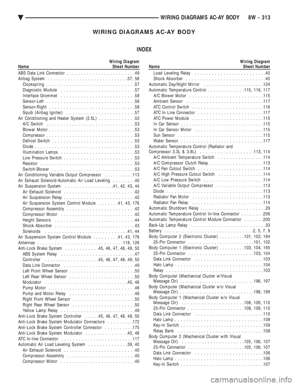
WIRING DIAGRAMS AC-AY BODY INDEX
Wiring Diagram
Name Sheet Number
ABS Data Link Connector ........................49
Airbag System ........................... .57, 58
Clockspring ...............................57
Diagnostic Module ..........................57
Interface Grommet ..........................58
Sensor-Left ...............................58
Sensor-Right ..............................58
Squib (Airbag Igniter) ........................57
Air Conditioning and Heater System (2.5L) .............53
A/C Switch ...............................53
Blower Motor ..............................53
Compressor ...............................53
Defrost Switch .............................53
Diode ...................................53
Illumination Lamps ..........................53
Low Pressure Switch .........................53
Resistor .................................53
Switch-Blower .............................53
Air Conditioning Variable Output Compressor ..........113
Air Exhaust Solenoid-Automatic Air Load Leveling ........40
Air Suspension System .................41, 42, 43, 44
Air Exhaust Solenoid .........................42
Air Suspension Relay .........................42
Air Suspension System Control Module .......41, 43, 176
Compressor Assembly ........................42
Compressor Motor ..........................42
Height Sensors ............................44
Shock Absorber ............................43
Solenoids ............................ .41, 44
Air Suspension System Control Module .........41, 43, 176
Antennas ............................. .118, 126
Anti-Lock Brake System ............45, 46, 47, 48, 49, 50
ABS System Relay ..........................47
Controller .................. .45, 46, 47, 48, 49, 50
Data Link Connector .........................49
Left Front Wheel Sensor .......................50
Left Rear Wheel Sensor .......................50
Modulator ............................ .45, 48
Pump Motor ..............................46
Pump and Motor Relay .......................46
Right Front Wheel Sensor ......................50
Right Rear Wheel Sensor ......................50
Yellow Lamp Relay ..........................49
Anti-Lock Brake System Controller .....45, 46, 47, 48, 49, 50
Anti-Lock Brake System Modulator Connectors .........172
Anti-Lock Brake System Controller Connector ..........175
Anti-Lock Brake System Modulator ...............45, 48
ATC In-line Connector ........................ .117
Automatic Air Load Leveling System ..............39, 40
Air Exhaust Solenoid .........................40
Compressor Assembly ........................40
Compressor Motor ..........................40Wiring Diagram
Name Sheet Number
Load Leveling Relay .........................40
Shock Absorber ............................40
Automatic Day/Night Mirror .................... .124
Automatic Temperature Control .............115, 116, 117
A/C Blower Motor ......................... .115
Ambient Sensor .......................... .117
ATC Control Switch ........................ .116
ATC In Line Connector ...................... .117
ATC Power Module ........................ .115
In Car Senso r............................ .115
In Car Sensor Motor ....................... .115
Sun Sensor ............................. .115
Water Sensor ............................ .117
Automatic Temperature Control (Radiator and
Compressor 3.3L & 3.8L) .................. .113, 114
A/C Ambient Temperature Switch ................114
A/C Compressor Clutch Relay ...................113
A/C Fan Cutout Switch ...................... .114
A/C High Pressure Cutout Switch ................114
A/C Low Pressure Switch .................... .114
A/C Variable Output Compressor .................113
Diode ................................. .113
Radiator Fan Motor ........................ .113
Radiator Fan Relay ........................ .114
Automatic Shutdown Relay .......................29
Automatic Temperature Control In-line Connector ........206
Automatic Temperature Control Module Connector .......200
Back-Up Lamp Relay ..........................33
Battery ...............................2,5,7,9
Body Computer 2 (Electronic Cluster) .........101, 102, 194
25-Pin Connector ...................... .101, 102
Body Computer 1 (Electronic Cluster) .........103, 104, 195
25-Pin Connector ...................... .103, 104
Data Link Connector ....................... .103
Halo Lamp .............................. .104
Relay ................................. .103
Body Computer (Mechanical Cluster w/Visual Message Ctr) ......................... .196, 197
Body Computer (Mechanical Cluster w/o Visual Message Ctr) ......................... .198, 199
Body Computer 1 (Mechanical Cluster w/o Visual Message Ctr) ..................... .108, 109, 110
25-Pin Connector ................... .108, 109, 110
Data Link Connector ....................... .110
Halo Lamp .............................. .108
Key-In Switch ............................ .109
Relay Bank ............................. .108
Body Computer 2 (Mechanical Cluster with Visual Message Ctr) ..................... .105, 106, 107
25-Pin Connector ................... .105, 106, 107
Data Link Connector ....................... .106
Halo Lamp .............................. .106
Key-In Switch ............................ .107
Ä WIRING DIAGRAMS AC-AY BODY 8W - 313
Page 1065 of 2438
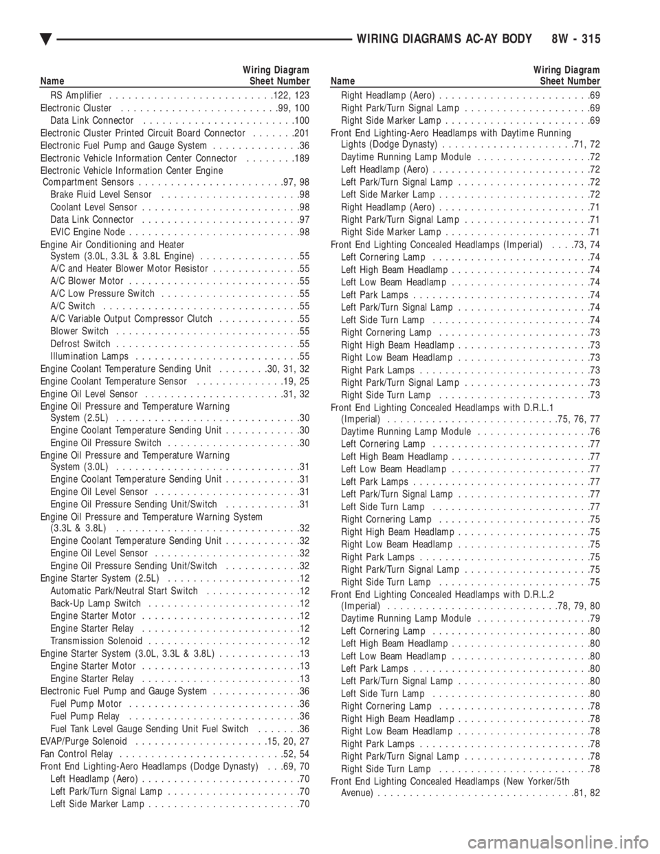
Wiring Diagram
Name Sheet Number
RS Amplifier ......................... .122, 123
Electronic Cluster ........................ .99, 100
Data Link Connector ....................... .100
Electronic Cluster Printed Circuit Board Connector .......201
Electronic Fuel Pump and Gauge System ..............36
Electronic Vehicle Information Center Connector ........189
Electronic Vehicle Information Center Engine Compartment Sensors ...................... .97, 98
Brake Fluid Level Sensor ......................98
Coolant Level Sensor .........................98
Data Link Connector .........................97
EVIC Engine Node ...........................98
Engine Air Conditioning and Heater System (3.0L, 3.3L & 3.8L Engine) ................55
A/C and Heater Blower Motor Resistor ..............55
A/C Blower Motor ...........................55
A/C Low Pressure Switch ......................55
A/C Switch ...............................55
A/C Variable Output Compressor Clutch .............55
Blower Switch .............................55
Defrost Switch .............................55
Illumination Lamps ..........................55
Engine Coolant Temperature Sending Unit ........30, 31, 32
Engine Coolant Temperature Sensor ..............19, 25
Engine Oil Level Sensor ..................... .31, 32
Engine Oil Pressure and Temperature Warning System (2.5L) .............................30
Engine Coolant Temperature Sending Unit ............30
Engine Oil Pressure Switch .....................30
Engine Oil Pressure and Temperature Warning System (3.0L) .............................31
Engine Coolant Temperature Sending Unit ............31
Engine Oil Level Sensor .......................31
Engine Oil Pressure Sending Unit/Switch ............31
Engine Oil Pressure and Temperature Warning System (3.3L & 3.8L) .............................32
Engine Coolant Temperature Sending Unit ............32
Engine Oil Level Sensor .......................32
Engine Oil Pressure Sending Unit/Switch ............32
Engine Starter System (2.5L) .....................12
Automatic Park/Neutral Start Switch ...............12
Back-Up Lamp Switch ........................12
Engine Starter Motor .........................12
Engine Starter Relay .........................12
Transmission Solenoid ........................12
Engine Starter System (3.0L, 3.3L & 3.8L) .............13
Engine Starter Motor .........................13
Engine Starter Relay .........................13
Electronic Fuel Pump and Gauge System ..............36
Fuel Pump Motor ...........................36
Fuel Pump Relay ...........................36
Fuel Tank Level Gauge Sending Unit Fuel Switch .......36
EVAP/Purge Solenoid .................... .15, 20, 27
Fan Control Relay ......................... .52, 54
Front End Lighting-Aero Headlamps (Dodge Dynasty) . . .69, 70 Left Headlamp (Aero) .........................70
Left Park/Turn Signal Lamp .....................70
Left Side Marker Lamp ........................70Wiring Diagram
Name Sheet Number
Right Headlamp (Aero) ........................69
Right Park/Turn Signal Lamp ....................69
Right Side Marker Lamp .......................69
Front End Lighting-Aero Headlamps with Daytime Running Lights (Dodge Dynasty) .................... .71, 72
Daytime Running Lamp Module ..................72
Left Headlamp (Aero) .........................72
Left Park/Turn Signal Lamp .....................72
Left Side Marker Lamp ........................72
Right Headlamp (Aero) ........................71
Right Park/Turn Signal Lamp ....................71
Right Side Marker Lamp .......................71
Front End Lighting Concealed Headlamps (Imperial) . . . .73, 74
Left Cornering Lamp .........................74
Left High Beam Headlamp ......................74
Left Low Beam Headlamp ......................74
Left Park Lamps ............................74
Left Park/Turn Signal Lamp .....................74
Left Side Turn Lamp .........................74
Right Cornering Lamp ........................73
Right High Beam Headlamp .....................73
Right Low Beam Headlamp .....................73
Right Park Lamps ...........................73
Right Park/Turn Signal Lamp ....................73
Right Side Turn Lamp ........................73
Front End Lighting Concealed Headlamps with D.R.L.1 (Imperial) .......................... .75, 76, 77
Daytime Running Lamp Module ..................76
Left Cornering Lamp .........................77
Left High Beam Headlamp ......................77
Left Low Beam Headlamp ......................77
Left Park Lamps ............................77
Left Park/Turn Signal Lamp .....................77
Left Side Turn Lamp .........................77
Right Cornering Lamp ........................75
Right High Beam Headlamp .....................75
Right Low Beam Headlamp .....................75
Right Park Lamps ...........................75
Right Park/Turn Signal Lamp ....................75
Right Side Turn Lamp ........................75
Front End Lighting Concealed Headlamps with D.R.L.2 (Imperial) .......................... .78, 79, 80
Daytime Running Lamp Module ..................79
Left Cornering Lamp .........................80
Left High Beam Headlamp ......................80
Left Low Beam Headlamp ......................80
Left Park Lamps ............................80
Left Park/Turn Signal Lamp .....................80
Left Side Turn Lamp .........................80
Right Cornering Lamp ........................78
Right High Beam Headlamp .....................78
Right Low Beam Headlamp .....................78
Right Park Lamps ...........................78
Right Park/Turn Signal Lamp ....................78
Right Side Turn Lamp ........................78
Front End Lighting Concealed Headlamps (New Yorker/5th Avenue) .............................. .81, 82
Ä WIRING DIAGRAMS AC-AY BODY 8W - 315
Page 1066 of 2438
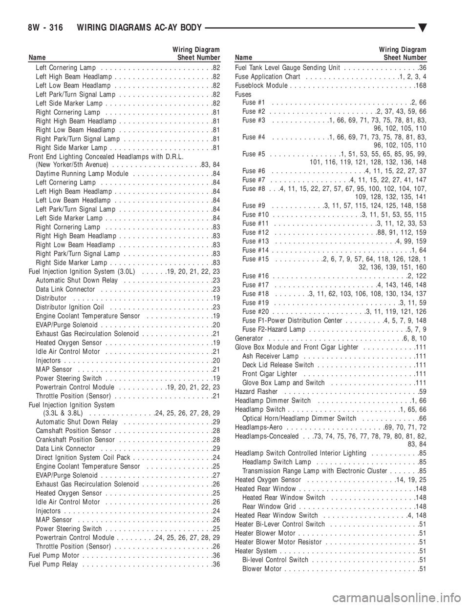
Wiring Diagram
Name Sheet Number
Left Cornering Lamp .........................82
Left High Beam Headlamp ......................82
Left Low Beam Headlamp ......................82
Left Park/Turn Signal Lamp .....................82
Left Side Marker Lamp ........................82
Right Cornering Lamp ........................81
Right High Beam Headlamp .....................81
Right Low Beam Headlamp .....................81
Right Park/Turn Signal Lamp ....................81
Right Side Marker Lamp .......................81
Front End Lighting Concealed Headlamps with D.R.L. (New Yorker/5th Avenue) ................... .83, 84
Daytime Running Lamp Module ..................84
Left Cornering Lamp .........................84
Left High Beam Headlamp ......................84
Left Low Beam Headlamp ......................84
Left Park/Turn Signal Lamp .....................84
Left Side Marker Lamp ........................84
Right Cornering Lamp ........................83
Right High Beam Headlamp .....................83
Right Low Beam Headlamp .....................83
Right Park/Turn Signal Lamp ....................83
Right Side Marker Lamp .......................83
Fuel Injection Ignition System (3.0L) ......19, 20, 21, 22, 23
Automatic Shut Down Relay ....................23
Data Link Connector .........................23
Distributor ...............................19
Distributor Ignition Coil .......................23
Engine Coolant Temperature Sensor ...............19
EVAP/Purge Solenoid .........................20
Exhaust Gas Recirculation Solenoid ................21
Heated Oxygen Sensor ........................19
Idle Air Control Motor ........................21
Injectors .................................20
MAP Sensor ..............................21
Power Steering Switch ........................19
Powertrain Control Module ...........19, 20, 21, 22, 23
Throttle Position (Sensor) ......................21
Fuel Injection Ignition System (3.3L & 3.8L) .............. .24, 25, 26, 27, 28, 29
Automatic Shut Down Relay ....................29
Camshaft Position Sensor ......................28
Crankshaft Position Sensor .....................28
Data Link Connector .........................29
Direct Ignition System Coil Pack ..................24
Engine Coolant Temperature Sensor ...............25
EVAP/Purge Solenoid .........................27
Exhaust Gas Recirculation Solenoid ................26
Heated Oxygen Sensor ........................25
Idle Air Control Motor ........................26
Injectors .................................24
MAP Sensor ..............................26
Power Steering Switch ........................25
Powertrain Control Module .........24, 25, 26, 27, 28, 29
Throttle Position (Sensor) ......................26
Fuel Pump Motor .............................36
Fuel Pump Relay .............................36Wiring Diagram
Name Sheet Number
Fuel Tank Level Gauge Sending Unit .................36
Fuse Application Chart .....................1,2,3,4
Fuseblock Module ........................... .168
Fuses Fuse #1 ...............................2,66
Fuse #2 ........................2,37,43,59,66
Fuse #3 .............1,66,69,71,73,75,78,81,83,
96, 102, 105, 110
Fuse #4 .............1,66,69,71,73,75,78,81,83,
96, 102, 105, 110
Fuse #5 ................1,51,53,55,65,85,95,99,
101, 116, 119, 121, 128, 132, 136, 148
Fuse #6 .....................4,11,15,22,27,37
Fuse #7 ..................4,11,15,22,27,41,147
Fuse #8 . . .4, 11, 15, 22, 27, 57, 67, 95, 100, 102, 104, 107, 109, 128, 132, 135, 141
Fuse #9 ............3,11,57, 115, 124, 125, 148, 158
Fuse #10 ....................3,11,51,53,55,115
Fuse #11 .......................3,11,12,33,53
Fuse #12 ...................... .88, 91, 112, 159
Fuse #13 ...........................4,99,159
Fuse #14 ...............................1,64
Fuse #15 ...........2,6,7,9,57,64, 118, 126, 128, 1
32, 136, 139, 151, 160
Fuse #16 ..............................2,122
Fuse #17 .......................4, 143, 146, 148
Fuse #18 ........3,11,62, 103, 106, 108, 130, 134, 137
Fuse #19 ............................3,11,59
Fuse #20 .....................3,11, 119, 121, 126
Fuse F1-Power Distribution Center .........4,5,7,9,148
Fuse F2-Hazard Lamp ......................5,7,9
Generator ..............................6,8,10
Glove Box Module and Front Cigar Lighter ............111
Ash Receiver Lamp ........................ .111
Deck Lid Release Switch ..................... .111
Front Cigar Lighter ........................ .111
Glove Box Lamp and Switch ...................111
Hazard Flasher ..............................59
Headlamp Dimmer Switch .....................1,66
Headlamp Switch .........................1,65,66
Optical Horn/Headlamp Dimmer Switch .............66
Headlamps-Aero ..................... .69, 70, 71, 72
Headlamps-Concealed . . .73, 74, 75, 76, 77, 78, 79, 80, 81, 82, 83, 84
Headlamp Switch Controlled Interior Lighting ...........85
Headlamp Switch Lamp .......................85
Transmission Range Lamp with Electronic Cluster .......85
Heated Oxygen Sensor ................... .14, 19, 25
Heated Rear Window ......................... .148
Heated Rear Window Switch ...................148
Rear Window Grid ......................... .148
Heated Rear Window Switch ...................4,148
Heater Bi-Lever Control Switch ....................51
Heater Blower Motor ...........................51
Heater Blower Motor Resistor .....................51
Heater System ...............................51
Bi-level Control Switch ........................51
Blower Motor ..............................51
8W - 316 WIRING DIAGRAMS AC-AY BODY Ä
Page 1067 of 2438
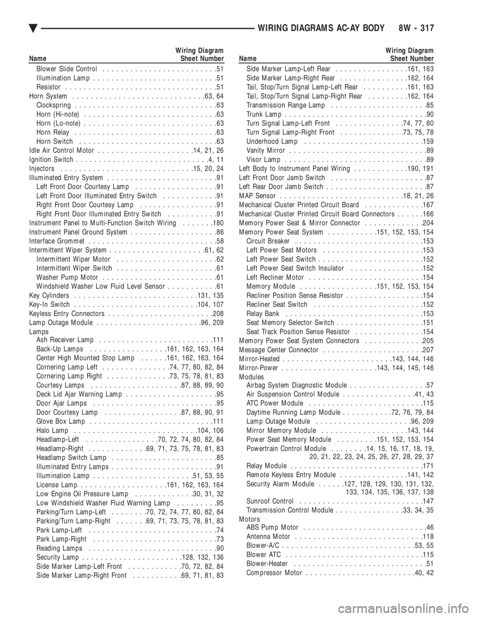
Wiring Diagram
Name Sheet Number
Blower Slide Control .........................51
Illumination Lamp ...........................51
Resistor .................................51
Horn System ............................ .63, 64
Clockspring ...............................63
Horn (Hi-note) .............................63
Horn (Lo-note) .............................63
Horn Relay ...............................63
Horn Switch ..............................63
Idle Air Control Motor .................... .14, 21, 26
Ignition Switch .............................4,11
Injectors ............................ .15, 20, 24
Illuminated Entry System ........................91
Left Front Door Courtesy Lamp ..................91
Left Front Door Illuminated Entry Switch ............91
Right Front Door Courtesy Lamp .................91
Right Front Door Illuminated Entry Switch ...........91
Instrument Panel to Multi-Function Switch Wiring .......180
Instrument Panel Ground System ...................86
Interface Grommet ............................58
Intermittent Wiper System .................... .61, 62
Intermittent Wiper Motor ......................62
Intermittent Wiper Switch ......................61
Washer Pump Motor .........................61
Windshield Washer Low Fluid Level Sensor ...........61
Key Cylinders .......................... .131, 135
Key-In Switch .......................... .104, 107
Keyless Entry Connectors ...................... .208
Lamp Outage Module ...................... .96, 209
Lamps Ash Receiver Lamp ........................ .111
Back-Up Lamps ................ .161, 162, 163, 164
Center High Mounted Stop Lamp ......161, 162, 163, 164
Cornering Lamp Left ...............74, 77, 80, 82, 84
Cornering Lamp Right ..............73, 75, 78, 81, 83
Courtesy Lamps ................... .87, 88, 89, 90
Deck Lid Ajar Warning Lamp ....................95
Door Ajar Lamps ...........................95
Door Courtesy Lamp ................ .87, 88, 90, 91
Glove Box Lamp .......................... .111
Halo Lamp .......................... .104, 106
Headlamp-Left ............... .70, 72, 74, 80, 82, 84
Headlamp-Right ............ .69, 71, 73, 75, 78, 81, 83
Headlamp Switch Lamp .......................85
Illuminated Entry Lamps .......................91
Illumination Lamp ..................... .51, 53, 55
License Lamp .................. .161, 162, 163, 164
Low Engine Oil Pressure Lamp .............30, 31, 32
Low Windshield Washer Fluid Warning Lamp .........95
Parking/Turn Lamp-Left ........70, 72, 74, 77, 80, 82, 84
Parking/Turn Lamp-Right .......69, 71, 73, 75, 78, 81, 83
Park Lamp-Left ............................74
Park Lamp-Right ...........................73
Reading Lamps ............................90
Security Lamp ..................... .128, 132, 136
Side Marker Lamp-Left Front ............70, 72, 82, 84
Side Marker Lamp-Right Front ...........69, 71, 81, 83Wiring Diagram
Name Sheet Number
Side Marker Lamp-Left Rear ................161, 163
Side Marker Lamp-Right Rear ...............162, 164
Tail, Stop/Turn Signal Lamp-Left Rear ..........161, 163
Tail, Stop/Turn Signal Lamp-Right Rear .........162, 164
Transmission Range Lamp .....................85
Trunk Lamp ...............................90
Turn Signal Lamp-Left Front ...............74, 77, 80
Turn Signal Lamp-Right Front ..............73, 75, 78
Underhood Lamp ......................... .159
Vanity Mirror ..............................89
Visor Lamp ...............................89
Left Body to Instrument Panel Wiring ............190, 191
Left Front Door Jamb Switch .....................87
Left Rear Door Jamb Switch ......................87
MAP Sensor .......................... .18, 21, 26
Mechanical Cluster Printed Circuit Board .............167
Mechanical Cluster Printed Circuit Board Connectors ......166
Memory Power Seat & Mirror Connector .............204
Memory Power Seat System ...........151, 152, 153, 154
Circuit Breaker ........................... .153
Left Power Seat Motors ..................... .153
Left Power Seat Switch ...................... .152
Left Power Seat Switch Insulator ................152
Left Recliner Motor ........................ .154
Memory Module ................ .151, 152, 153, 154
Recliner Position Sense Resistor .................154
Recliner Seat Switch ....................... .152
Relay Bank ............................. .153
Seat Memory Selector Switch ...................151
Seat Track Position Sense Resistor ...............154
Memory Power Seat System Connectors .............205
Message Center Connector ..................... .207
Mirror-Heated ....................... .143, 144, 146
Mirror-Power .................... .143, 144, 145, 146
Modules Airbag System Diagnostic Module .................57
Air Suspension Control Module ................41, 43
ATC Power Module ........................ .115
Daytime Running Lamp Module ...........72, 76, 79, 84
Lamp Outage Module .................... .96, 209
Mirror Memory Module .................. .143, 144
Power Seat Memory Module .........151, 152, 153, 154
Powertrain Control Module ........14, 15, 16, 17, 18, 19,
20, 21, 22, 23, 24, 25, 26, 27, 28, 29, 37
Relay Module ............................ .171
Remote Keyless Entry Module ...............141, 142
Security Alarm Module ......127, 128, 129, 130, 131, 132,
133, 134, 135, 136, 137, 138
Sunroof Control .......................... .147
Transmission Control Module ...............33, 34, 35
Motors ABS Pump Motor ...........................46
Antenna Motor ........................... .118
Blower-A/C ............................ .53, 55
Blower ATC ............................. .115
Blower-Heater .............................51
Compressor Motor ....................... .40, 42
Ä WIRING DIAGRAMS AC-AY BODY 8W - 317
Page 1068 of 2438
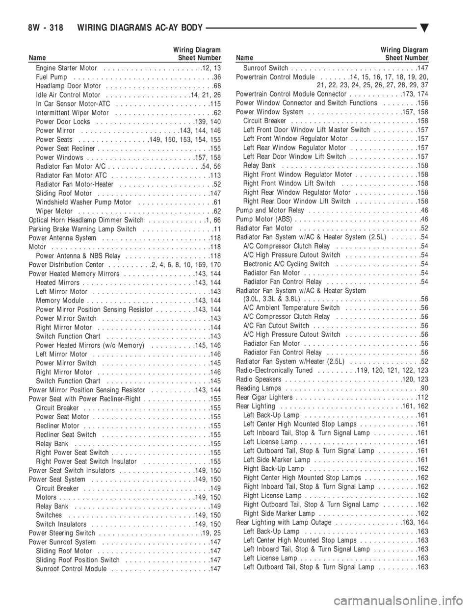
Wiring Diagram
Name Sheet Number
Engine Starter Motor ..................... .12, 13
Fuel Pump ...............................36
Headlamp Door Motor ........................68
Idle Air Control Motor .................. .14, 21, 26
In Car Sensor Motor-ATC .................... .115
Intermittent Wiper Motor ......................62
Power Door Locks ..................... .139, 140
Power Mirror ..................... .143, 144, 146
Power Seats ............... .149, 150, 153, 154, 155
Power Seat Recliner ........................ .155
Power Windows ....................... .157, 158
Radiator Fan Motor A/C .................... .54, 56
Radiator Fan Motor ATC ..................... .113
Radiator Fan Motor-Heater .....................52
Sliding Roof Motor ........................ .147
Windshield Washer Pump Motor .................61
Wiper Motor ..............................62
Optical Horn Headlamp Dimmer Switch .............1,66
Parking Brake Warning Lamp Switch ................11
Power Antenna System ....................... .118
Motor .................................. .118
Power Antenna & NBS Relay ...................118
Power Distribution Center ..........2,4,6,8,10, 169, 170
Power Heated Memory Mirrors ................143, 144
Heated Mirror s........................ .143, 144
Left Mirror Motor ......................... .143
Memory Module ....................... .143, 144
Power Mirror Position Sensing Resistor .........143, 144
Power Mirror Switch ....................... .143
Right Mirror Motor ........................ .144
Switch Function Chart ...................... .143
Power Heated Mirrors (w/o Memory) ..........145, 146
Left Mirror Motor ......................... .146
Power Mirror Switch ....................... .145
Right Mirror Motor ........................ .146
Switch Function Chart ...................... .145
Power Mirror Position Sensing Resistor ..........143, 144
Power Seat with Power Recliner-Right ...............155
Circuit Breaker ........................... .155
Power Seat Motor ......................... .155
Recliner Motor ........................... .155
Recliner Seat Switch ....................... .155
Relay Bank ............................. .155
Right Power Seat Switch ..................... .155
Right Power Seat Switch Insulator ...............155
Power Seat Switch Insulators .................149, 150
Power Seat System ...................... .149, 150
Circuit Breaker ........................... .149
Motors ............................. .149, 150
Relay Bank ............................. .149
Switches ........................... .149, 150
Switch Insulators ...................... .149, 150
Power Steering Switch ...................... .19, 25
Power Sunroof System ....................... .147
Sliding Roof Motor ........................ .147
Sliding Roof Position Switch ...................147
Sunroof Control Module ..................... .147Wiring Diagram
Name Sheet Number
Sunroof Switch ........................... .147
Powertrain Control Module .......14, 15, 16, 17, 18, 19, 20,
21, 22, 23, 24, 25, 26, 27, 28, 29, 37
Powertrain Control Module Connector ............173, 174
Power Window Connector and Switch Functions ........156
Power Window System .................... .157, 158
Circuit Breaker ........................... .158
Left Front Door Window Lift Master Switch ..........157
Left Front Window Regulator Motor ...............157
Left Rear Window Regulator Motor ...............157
Left Rear Door Window Lift Switch ...............157
Relay Bank ............................. .158
Right Front Window Regulator Motor ..............158
Right Front Window Lift Switch .................158
Right Rear Window Regulator Motor ..............158
Right Rear Door Window Lift Switch ..............158
Pump and Motor Relay .........................46
Pump Motor (ABS) ............................46
Radiator Fan Motor ...........................52
Radiator Fan System w/AC & Heater System (2.5L) .......54
A/C Compressor Clutch Relay ...................54
A/C High Pressure Cutout Switch .................54
Electronic A/C Cycling Switch ...................54
Radiator Fan Motor ..........................54
Radiator Fan Control Relay .....................54
Radiator Fan System w/AC & Heater System (3.0L, 3.3L & 3.8L) ..........................56
A/C Ambient Temperature Switch .................56
A/C Compressor Clutch Relay ...................56
A/C Fan Cutout Switch ........................56
A/C High Pressure Cutout Switch .................56
Radiator Fan Motor ..........................56
Radiator Fan Control Relay .....................56
Radiator Fan System w/Heater (2.5L) ................52
Radio-Electronically Tuned .........119, 120, 121, 122, 123
Radio Speakers ......................... .120, 123
Reading Lamps ..............................90
Rear Cigar Lighters .......................... .112
Rear Lighting .......................... .161, 162
Left Back-Up Lamp ........................ .161
Left Center High Mounted Stop Lamps .............161
Left Inboard Tail, Stop & Turn Signal Lamp ..........161
Left License Lamp ......................... .161
Left Outboard Tail, Stop & Turn Signal Lamp .........161
Left Side Marker Lamp ...................... .161
Right Back-Up Lamp ....................... .162
Right Center High Mounted Stop Lamps ............162
Right Inboard Tail, Stop & Turn Signal Lamp .........162
Right License Lamp ........................ .162
Right Outboard Tail, Stop & Turn Signal Lamp ........162
Right Side Marker Lamp ..................... .162
Rear Lighting with Lamp Outage ...............163, 164
Left Back-Up Lamp ........................ .163
Left Center High Mounted Stop Lamps .............163
Left Inboard Tail, Stop & Turn Signal Lamp ..........163
Left License Lamp ......................... .163
Left Outboard Tail, Stop & Turn Signal Lamp .........163
8W - 318 WIRING DIAGRAMS AC-AY BODY Ä