fuel CHEVROLET DYNASTY 1993 Service Manual
[x] Cancel search | Manufacturer: CHEVROLET, Model Year: 1993, Model line: DYNASTY, Model: CHEVROLET DYNASTY 1993Pages: 2438, PDF Size: 74.98 MB
Page 1912 of 2438
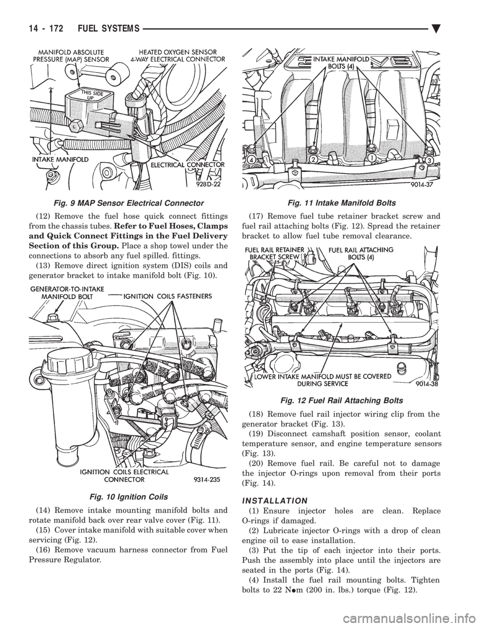
(12) Remove the fuel hose quick connect fittings
from the chassis tubes. Refer to Fuel Hoses, Clamps
and Quick Connect Fittings in the Fuel Delivery
Section of this Group. Place a shop towel under the
connections to absorb any fuel spilled. fittings. (13) Remove direct ignition system (DIS) coils and
generator bracket to intake manifold bolt (Fig. 10).
(14) Remove intake mounting manifold bolts and
rotate manifold back over rear valve cover (Fig. 11). (15) Cover intake manifold with suitable cover when
servicing (Fig. 12). (16) Remove vacuum harness connector from Fuel
Pressure Regulator. (17) Remove fuel tube retainer bracket screw and
fuel rail attaching bolts (Fig. 12). Spread the retainer
bracket to allow fuel tube removal clearance.
(18) Remove fuel rail injector wiring clip from the
generator bracket (Fig. 13). (19) Disconnect camshaft position sensor, coolant
temperature sensor, and engine temperature sensors
(Fig. 13). (20) Remove fuel rail. Be careful not to damage
the injector O-rings upon removal from their ports
(Fig. 14).
INSTALLATION
(1) Ensure injector holes are clean. Replace
O-rings if damaged. (2) Lubricate injector O-rings with a drop of clean
engine oil to ease installation. (3) Put the tip of each injector into their ports.
Push the assembly into place until the injectors are
seated in the ports (Fig. 14). (4) Install the fuel rail mounting bolts. Tighten
bolts to 22 N Im (200 in. lbs.) torque (Fig. 12).
Fig. 11 Intake Manifold Bolts
Fig. 12 Fuel Rail Attaching Bolts
Fig. 9 MAP Sensor Electrical Connector
Fig. 10 Ignition Coils
14 - 172 FUEL SYSTEMS Ä
Page 1913 of 2438
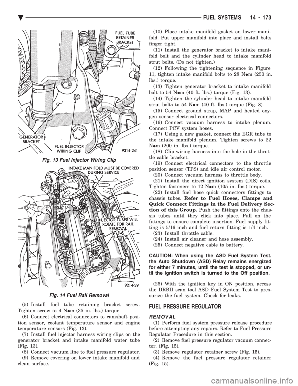
(5) Install fuel tube retaining bracket screw.
Tighten screw to 4 N Im (35 in. lbs.) torque.
(6) Connect electrical connectors to camshaft posi-
tion sensor, coolant temperature sensor and engine
temperature sensors (Fig. 13). (7) Install fuel injector harness wiring clips on the
generator bracket and intake manifold water tube
(Fig. 13). (8) Connect vacuum line to fuel pressure regulator.
(9) Remove covering on lower intake manifold and
clean surface. (10) Place intake manifold gasket on lower mani-
fold. Put upper manifold into place and install bolts
finger tight. (11) Install the generator bracket to intake mani-
fold bolt and the cylinder head to intake manifold
strut bolts. (Do not tighten.) (12) Following the tightening sequence in Figure
11, tighten intake manifold bolts to 28 N Im (250 in.
lbs.) torque. (13) Tighten generator bracket to intake manifold
bolt to 54 N Im (40 ft. lbs.) torque (Fig. 13).
(14) Tighten the cylinder head to intake manifold
strut bolts to 54 N Im (40 ft. lbs.) torque (Fig. 8).
(15) Connect ground strap, MAP and heated oxy-
gen sensor electrical connectors. (16) Connect vacuum harness to intake plenum.
Connect PCV system hoses. (17) Using a new gasket, connect the EGR tube to
the intake manifold plenum. Tighten screws to 22
N Im (200 in. lbs.) torque.
(18) Clip wiring harness into the hole in the throt-
tle cable bracket. (19) Connect electrical connectors to the throttle
position sensor (TPS) and idle air control motor. (20) Connect vacuum harness to throttle body.
(21) Install the direct ignition system (DIS) coils.
Tighten fasteners to 12 N Im (105 in. lbs.) torque.
(22) Install fuel hose quick connectors fittings to
chassis tubes. Refer to Fuel Hoses, Clamps and
Quick Connect Fittings in the Fuel Delivery Sec-
tion of this Group. Push the fittings onto the chas-
sis tubes until they click into place. Pull on the
fittings to ensure complete insertion. Fuel supply fit-
ting is 5/16 inch and fuel return fitting is 1/4 inch. (23) Install throttle cable.
(24) Install air cleaner and hose assembly.
(25) Connect negative cable to battery.
CAUTION: When using the ASD Fuel System Test,
the Auto Shutdown (ASD) Relay remains energized
for either 7 minutes, until the test is stopped, or un-
til the ignition switch is turned to the Off position.
(26) With the ignition key in ON position, access
the DRBII scan tool ASD Fuel System Test to pres-
surize the fuel system. Check for leaks.FUEL PRESSURE REGULATOR
REMOVAL
(1) Perform fuel system pressure release procedure
before attempting any repairs. Refer to Fuel Pressure
Regulator Procedure in this section. (2) Remove fuel pressure regulator vacuum connec-
tor. (Fig. 15). (3) Remove regulator retainer screw (Fig. 15).
(4) Remove the fuel pressure regulator retainer
(Fig. 15).
Fig. 13 Fuel Injector Wiring Clip
Fig. 14 Fuel Rail Removal
Ä FUEL SYSTEMS 14 - 173
Page 1914 of 2438
WARNING: PLACE A SHOP TOWEL UNDER FUEL
PRESSURE REGULATOR TO ABSORB ANY FUEL
SPILLAGE.
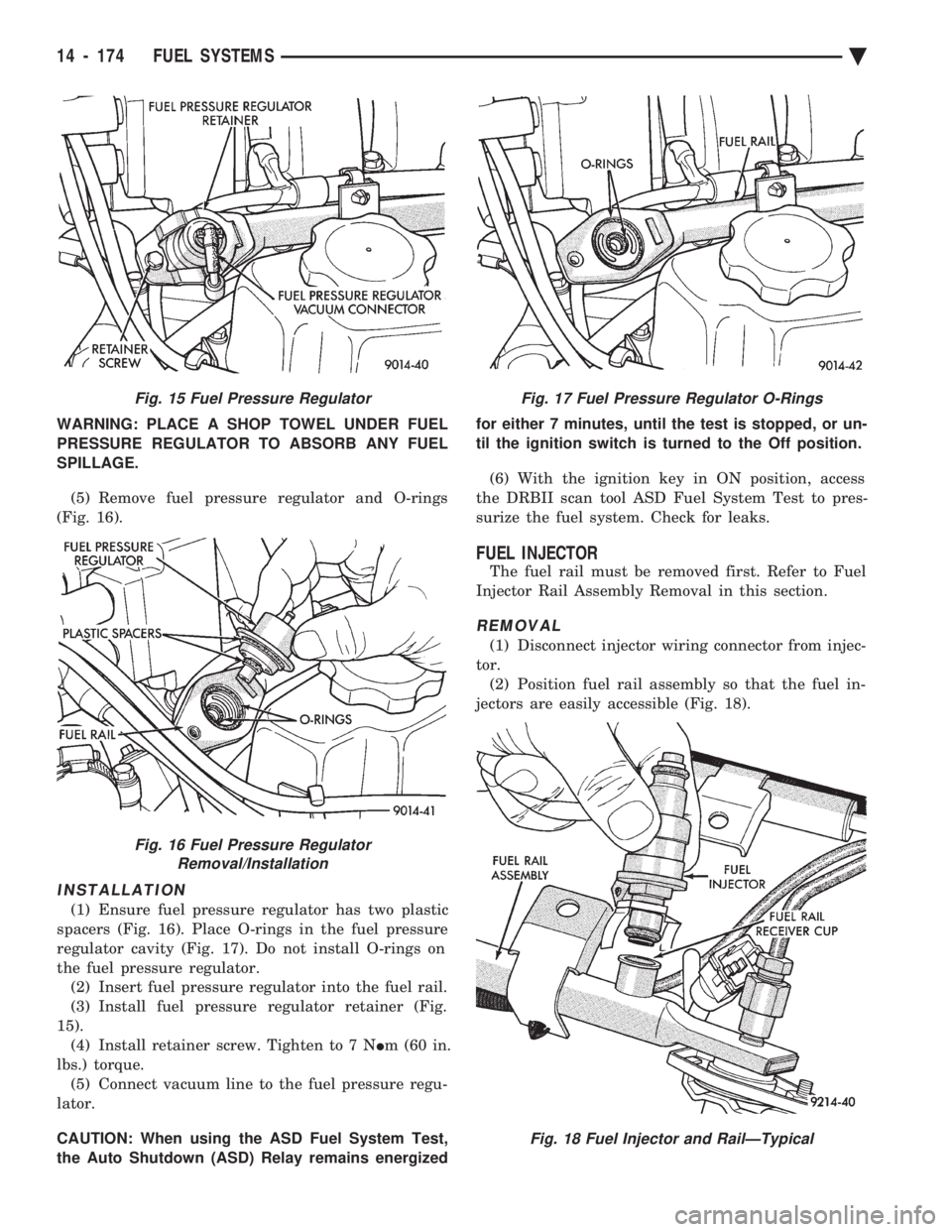
(5) Remove fuel pressure regulator and O-rings
(Fig. 16).
INSTALLATION
(1) Ensure fuel pressure regulator has two plastic
spacers (Fig. 16). Place O-rings in the fuel pressure
regulator cavity (Fig. 17). Do not install O-rings on
the fuel pressure regulator. (2) Insert fuel pressure regulator into the fuel rail.
(3) Install fuel pressure regulator retainer (Fig.
15). (4) Install retainer screw. Tighten to 7 N Im (60 in.
lbs.) torque. (5) Connect vacuum line to the fuel pressure regu-
lator.
CAUTION: When using the ASD Fuel System Test,
the Auto Shutdown (ASD) Relay remains energized for either 7 minutes, until the test is stopped, or un-
til the ignition switch is turned to the Off position.
(6) With the ignition key in ON position, access
the DRBII scan tool ASD Fuel System Test to pres-
surize the fuel system. Check for leaks.
FUEL INJECTOR
The fuel rail must be removed first. Refer to Fuel
Injector Rail Assembly Removal in this section.
REMOVAL
(1) Disconnect injector wiring connector from injec-
tor. (2) Position fuel rail assembly so that the fuel in-
jectors are easily accessible (Fig. 18).
Fig. 15 Fuel Pressure Regulator
Fig. 16 Fuel Pressure Regulator Removal/Installation
Fig. 17 Fuel Pressure Regulator O-Rings
Fig. 18 Fuel Injector and RailÐTypical
14 - 174 FUEL SYSTEMS Ä
Page 1915 of 2438
(3) Rotate injector and pull injector out of fuel rail.
The clip will stay on the injector. (4) Check injector O-ring for damage. If O-ring is
damaged, it must be replaced. If injector is reused, a
protective cap must be installed on the injector tip to
prevent damage. Replace the injector clip if it is
damaged. (5) Repeat for remaining injectors.
INSTALLATION
(1) Before installing an injector the rubber O-ring
must be lubricated with a drop of clean engine oil to
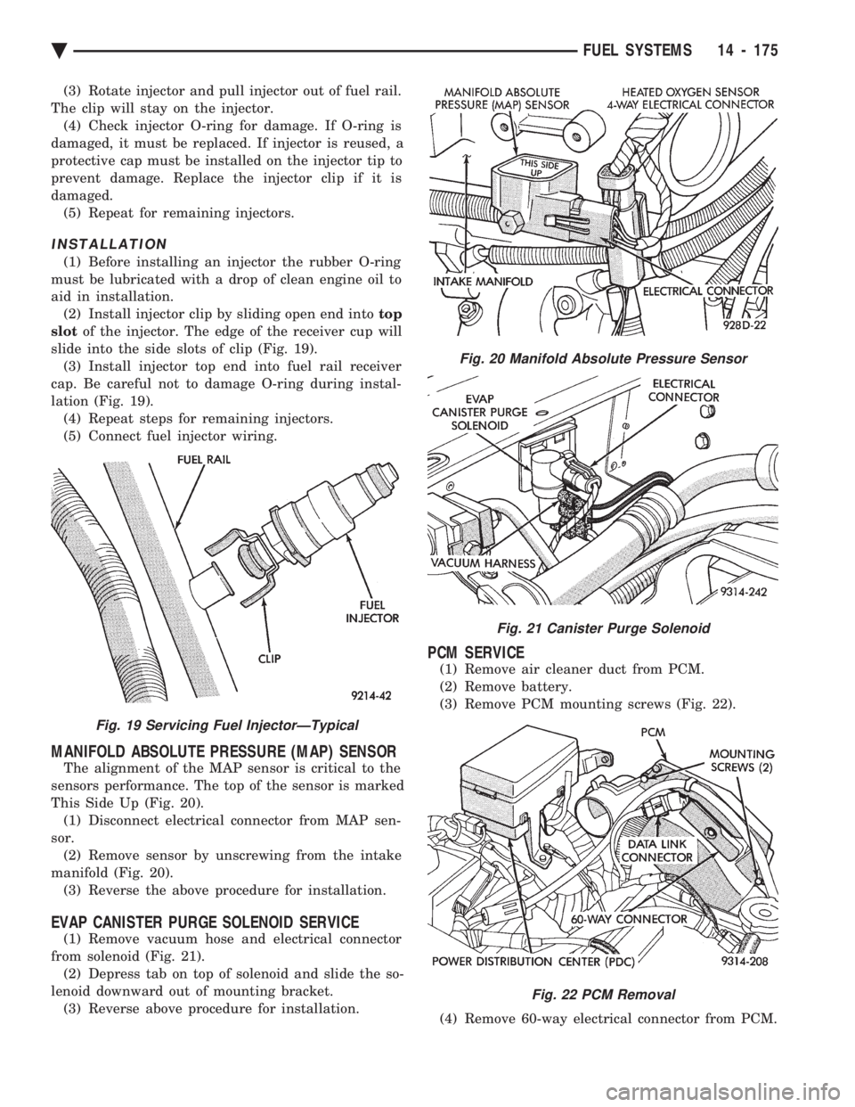
aid in installation. (2) Install injector clip by sliding open end into top
slot of the injector. The edge of the receiver cup will
slide into the side slots of clip (Fig. 19). (3) Install injector top end into fuel rail receiver
cap. Be careful not to damage O-ring during instal-
lation (Fig. 19). (4) Repeat steps for remaining injectors.
(5) Connect fuel injector wiring.
MANIFOLD ABSOLUTE PRESSURE (MAP) SENSOR
The alignment of the MAP sensor is critical to the
sensors performance. The top of the sensor is marked
This Side Up (Fig. 20). (1) Disconnect electrical connector from MAP sen-
sor. (2) Remove sensor by unscrewing from the intake
manifold (Fig. 20). (3) Reverse the above procedure for installation.
EVAP CANISTER PURGE SOLENOID SERVICE
(1) Remove vacuum hose and electrical connector
from solenoid (Fig. 21). (2) Depress tab on top of solenoid and slide the so-
lenoid downward out of mounting bracket. (3) Reverse above procedure for installation.
PCM SERVICE
(1) Remove air cleaner duct from PCM.
(2) Remove battery.
(3) Remove PCM mounting screws (Fig. 22).
(4) Remove 60-way electrical connector from PCM.
Fig. 19 Servicing Fuel InjectorÐTypical
Fig. 20 Manifold Absolute Pressure Sensor
Fig. 21 Canister Purge Solenoid
Fig. 22 PCM Removal
Ä FUEL SYSTEMS 14 - 175
Page 1916 of 2438
(5) Reverse the above procedure for installation.
CRANKSHAFT POSITION SENSOR
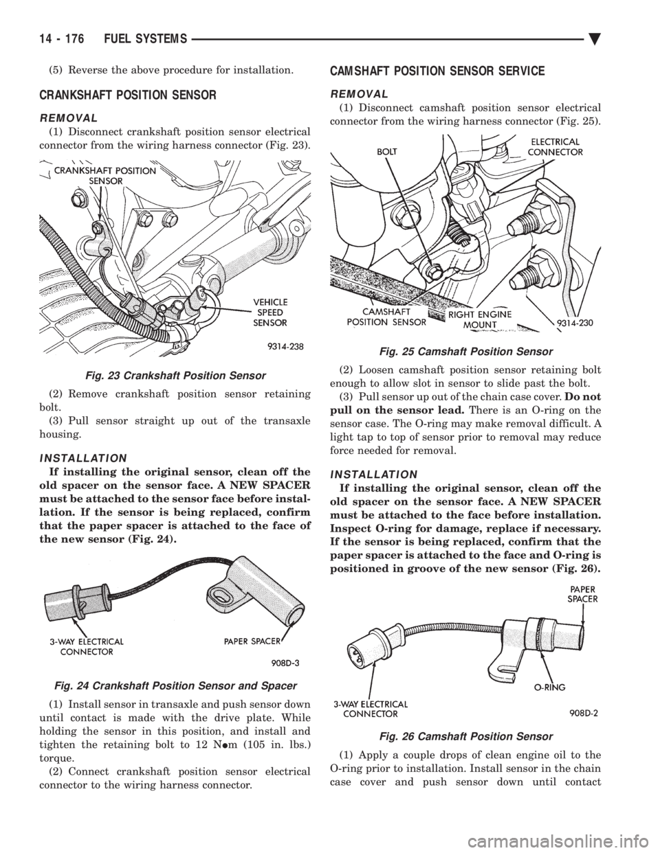
REMOVAL
(1) Disconnect crankshaft position sensor electrical
connector from the wiring harness connector (Fig. 23).
(2) Remove crankshaft position sensor retaining
bolt. (3) Pull sensor straight up out of the transaxle
housing.
INSTALLATION
If installing the original sensor, clean off the
old spacer on the sensor face. A NEW SPACER
must be attached to the sensor face before instal-
lation. If the sensor is being replaced, confirm
that the paper spacer is attached to the face of
the new sensor (Fig. 24).
(1) Install sensor in transaxle and push sensor down
until contact is made with the drive plate. While
holding the sensor in this position, and install and
tighten the retaining bolt to 12 N Im (105 in. lbs.)
torque. (2) Connect crankshaft position sensor electrical
connector to the wiring harness connector.
CAMSHAFT POSITION SENSOR SERVICE
REMOVAL
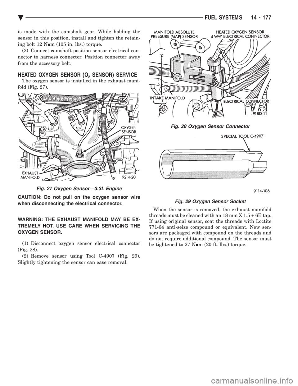
(1) Disconnect camshaft position sensor electrical
connector from the wiring harness connector (Fig. 25).
(2) Loosen camshaft position sensor retaining bolt
enough to allow slot in sensor to slide past the bolt. (3) Pull sensor up out of the chain case cover. Do not
pull on the sensor lead. There is an O-ring on the
sensor case. The O-ring may make removal difficult. A
light tap to top of sensor prior to removal may reduce
force needed for removal.
INSTALLATION
If installing the original sensor, clean off the
old spacer on the sensor face. A NEW SPACER
must be attached to the face before installation.
Inspect O-ring for damage, replace if necessary.
If the sensor is being replaced, confirm that the
paper spacer is attached to the face and O-ring is
positioned in groove of the new sensor (Fig. 26).
(1) Apply a couple drops of clean engine oil to the
O-ring prior to installation. Install sensor in the chain
case cover and push sensor down until contact
Fig. 23 Crankshaft Position Sensor
Fig. 24 Crankshaft Position Sensor and Spacer
Fig. 25 Camshaft Position Sensor
Fig. 26 Camshaft Position Sensor
14 - 176 FUEL SYSTEMS Ä
Page 1917 of 2438
is made with the camshaft gear. While holding the
sensor in this position, install and tighten the retain-
ing bolt 12 N Im (105 in. lbs.) torque.
(2) Connect camshaft position sensor electrical con-
nector to harness connector. Position connector away
from the accessory belt.
HEATED OXYGEN SENSOR (O2SENSOR) SERVICE
The oxygen sensor is installed in the exhaust mani-
fold (Fig. 27).
CAUTION: Do not pull on the oxygen sensor wire
when disconnecting the electrical connector.
WARNING: THE EXHAUST MANIFOLD MAY BE EX-
TREMELY HOT. USE CARE WHEN SERVICING THE
OXYGEN SENSOR.
(1) Disconnect oxygen sensor electrical connector
(Fig. 28). (2) Remove sensor using Tool C-4907 (Fig. 29).
Slightly tightening the sensor can ease removal. When the sensor is removed, the exhaust manifold
threads must be cleaned with an 18 mm X 1.5 + 6E tap.
If using original sensor, coat the threads with Loctite
771-64 anti-seize compound or equivalent. New sen-
sors are packaged with compound on the threads and
do not require additional compound. The sensor must
be tightened to 27 N Im (20 ft. lbs.) torque.
Fig. 27 Oxygen SensorÐ3.3L Engine
Fig. 28 Oxygen Sensor Connector
Fig. 29 Oxygen Sensor Socket
Ä FUEL SYSTEMS 14 - 177
Page 1918 of 2438
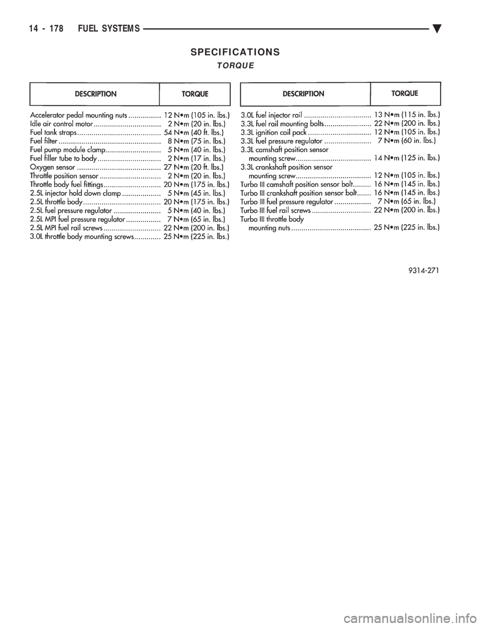
SPECIFICATIONS
TORQUE
14 - 178 FUEL SYSTEMS Ä
Page 2150 of 2438
PRESSURE GAUGES
High quality dial type air pressure gauges are rec-
ommended. After checking pressure with the gauge,
replace valve caps and tighten finger tight.
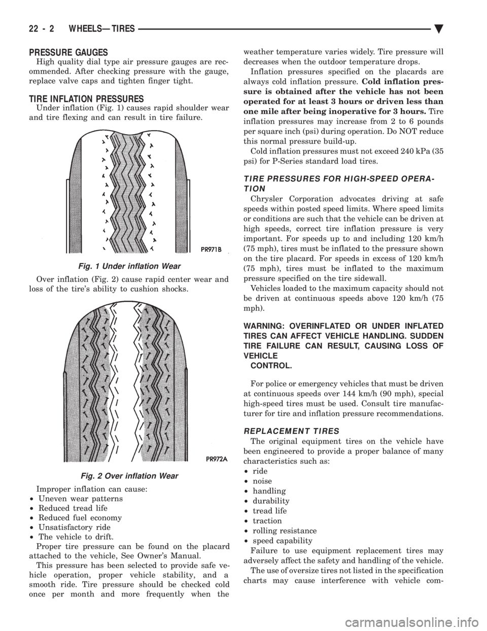
TIRE INFLATION PRESSURES
Under inflation (Fig. 1) causes rapid shoulder wear
and tire flexing and can result in tire failure.
Over inflation (Fig. 2) cause rapid center wear and
loss of the tire's ability to cushion shocks.
Improper inflation can cause:
² Uneven wear patterns
² Reduced tread life
² Reduced fuel economy
² Unsatisfactory ride
² The vehicle to drift.
Proper tire pressure can be found on the placard
attached to the vehicle, See Owner's Manual. This pressure has been selected to provide safe ve-
hicle operation, proper vehicle stability, and a
smooth ride. Tire pressure should be checked cold
once per month and more frequently when the weather temperature varies widely. Tire pressure will
decreases when the outdoor temperature drops.
Inflation pressures specified on the placards are
always cold inflation pressure. Cold inflation pres-
sure is obtained after the vehicle has not been
operated for at least 3 hours or driven less than
one mile after being inoperative for 3 hours. Tire
inflation pressures may increase from 2 to 6 pounds
per square inch (psi) during operation. Do NOT reduce
this normal pressure build-up. Cold inflation pressures must not exceed 240 kPa (35
psi) for P-Series standard load tires.
TIRE PRESSURES FOR HIGH-SPEED OPERA- TION
Chrysler Corporation advocates driving at safe
speeds within posted speed limits. Where speed limits
or conditions are such that the vehicle can be driven at
high speeds, correct tire inflation pressure is very
important. For speeds up to and including 120 km/h
(75 mph), tires must be inflated to the pressure shown
on the tire placard. For speeds in excess of 120 km/h
(75 mph), tires must be inflated to the maximum
pressure specified on the tire sidewall. Vehicles loaded to the maximum capacity should not
be driven at continuous speeds above 120 km/h (75
mph).
WARNING: OVERINFLATED OR UNDER INFLATED
TIRES CAN AFFECT VEHICLE HANDLING. SUDDEN
TIRE FAILURE CAN RESULT, CAUSING LOSS OF
VEHICLE CONTROL.
For police or emergency vehicles that must be driven
at continuous speeds over 144 km/h (90 mph), special
high-speed tires must be used. Consult tire manufac-
turer for tire and inflation pressure recommendations.
REPLACEMENT TIRES
The original equipment tires on the vehicle have
been engineered to provide a proper balance of many
characteristics such as:
² ride
² noise
² handling
² durability
² tread life
² traction
² rolling resistance
² speed capability
Failure to use equipment replacement tires may
adversely affect the safety and handling of the vehicle. The use of oversize tires not listed in the specification
charts may cause interference with vehicle com-
Fig. 1 Under inflation Wear
Fig. 2 Over inflation Wear
22 - 2 WHEELSÐTIRES Ä
Page 2167 of 2438
AA-VEHICLE BODY COMPONENT SERVICE INDEX
page page
A-Pillar and Roof Rail Mouldings ............. 25
B-Pillar Trim Panel ....................... 25
Body Side Moulding and Applique ............ 24
Cowl Cover ............................. 13
Cowl Panel Trim and Scuff Plates ............ 25
Door Opening Weatherstrips ................ 24
Floor Carpet ............................ 30
Front Center Console ..................... 29
Front Door and Hinge ..................... 15
Front Door Belt Moulding and Weatherstrip ..... 17
Front Door Glass ........................ 17
Front Door Glass Channel and Run Weatherstrip . 18
Front Door Glass Run Lower Channel ......... 18
Front Door Latch ......................... 16
Front Door Side View Mirror ................ 17
Front Door Silencer and Water Shield ......... 15
Front Door Trim Panel .................... 14
Front Door Window Regulator/Manual ......... 18
Front Door Window Regulator/Power .......... 19
Front End Splash Shields .................. 13
Front Fender ............................ 14
Front Power Door Lock Actuator ............. 19
Front Seat Belts ......................... 27
Front Seats ............................. 28
Fuel Fill Door ........................... 36
Grille .................................. 11
Head Lining ............................. 30
Hood and Hinges ........................ 11
Hood Latch and Release Cable .............. 12
Outside Front Door Latch Release Handle ..... 16
Outside Rear Door Latch Release Handle ...... 21 Overhead Console
........................ 30
Quarter Extension Trim Panel ............... 27
Quarter Trim Panel ....................... 27
Rear Deck Filler Panel .................... 31
Rear Door and Hinge ..................... 20
Rear Door Belt Moulding and Weatherstrip ..... 22
Rear Door Glass ......................... 22
Rear Door Glass Run Weatherstrip ........... 22
Rear Door Glass Stationary Glass Module ..... 23
Rear Door Latch ......................... 21
Rear Door Silencer and Water Shield ......... 20
Rear Door Trim Panel ..................... 20
Rear Door Window Regulator/Manual ......... 23
Rear Door Window Regulator/Power .......... 23
Rear Power Door Lock Actuator ............. 22
Rear Seat Belts .......................... 28
Rear Seats ............................. 28
Rear Shelf Trim Panel ..................... 27
Rear Window Glass ...................... 32
Sun Roof Air Deflector .................... 31
Sun Roof Drain Tubes .................... 31
Sun Roof Weatherstrip .................... 31
Trunk Lid .............................. 33
Trunk Lid Hinge ......................... 34
Trunk Lid Latch .......................... 34
Trunk Lid Lock .......................... 34
Trunk Lid Luggage Rack ................... 35
Trunk Lid Torsion Bar ..................... 34
Trunk Lining ............................ 35
Trunk Opening Weatherstrip ................ 35
Vinyl Roof Bonnet ........................ 31
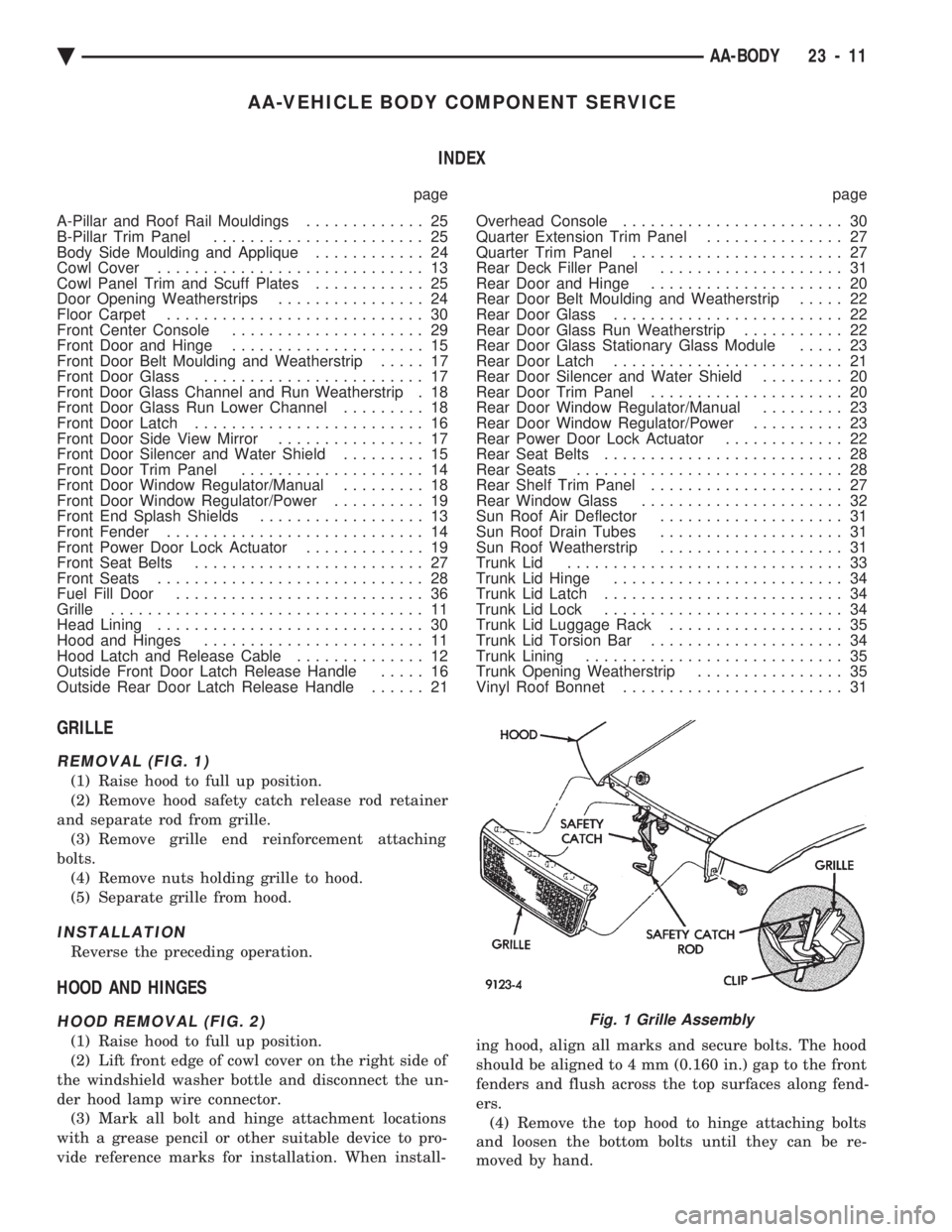
GRILLE
REMOVAL (FIG. 1)
(1) Raise hood to full up position.
(2) Remove hood safety catch release rod retainer
and separate rod from grille. (3) Remove grille end reinforcement attaching
bolts. (4) Remove nuts holding grille to hood.
(5) Separate grille from hood.
INSTALLATION
Reverse the preceding operation.
HOOD AND HINGES
HOOD REMOVAL (FIG. 2)
(1) Raise hood to full up position.
(2) Lift front edge of cowl cover on the right side of
the windshield washer bottle and disconnect the un-
der hood lamp wire connector. (3) Mark all bolt and hinge attachment locations
with a grease pencil or other suitable device to pro-
vide reference marks for installation. When install- ing hood, align all marks and secure bolts. The hood
should be aligned to 4 mm (0.160 in.) gap to the front
fenders and flush across the top surfaces along fend-
ers. (4) Remove the top hood to hinge attaching bolts
and loosen the bottom bolts until they can be re-
moved by hand.
Fig. 1 Grille Assembly
Ä AA-BODY 23 - 11
Page 2191 of 2438
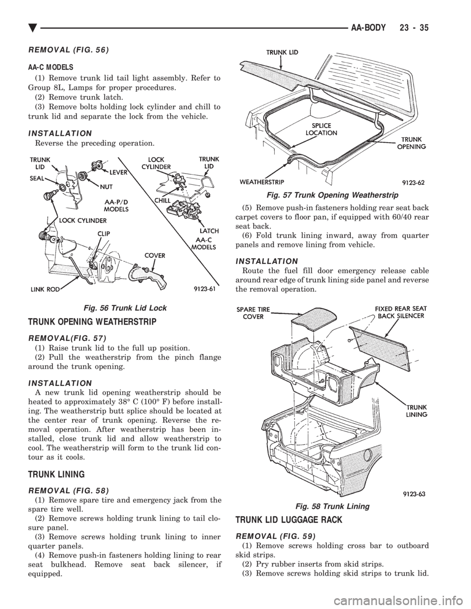
REMOVAL (FIG. 56)
AA-C MODELS (1) Remove trunk lid tail light assembly. Refer to
Group 8L, Lamps for proper procedures. (2) Remove trunk latch.
(3) Remove bolts holding lock cylinder and chill to
trunk lid and separate the lock from the vehicle.
INSTALLATION
Reverse the preceding operation.
TRUNK OPENING WEATHERSTRIP
REMOVAL(FIG. 57)
(1) Raise trunk lid to the full up position.
(2) Pull the weatherstrip from the pinch flange
around the trunk opening.
INSTALLATION
A new trunk lid opening weatherstrip should be
heated to approximately 38É C (100É F) before install-
ing. The weatherstrip butt splice should be located at
the center rear of trunk opening. Reverse the re-
moval operation. After weatherstrip has been in-
stalled, close trunk lid and allow weatherstrip to
cool. The weatherstrip will form to the trunk lid con-
tour as it cools.
TRUNK LINING
REMOVAL (FIG. 58)
(1) Remove spare tire and emergency jack from the
spare tire well. (2) Remove screws holding trunk lining to tail clo-
sure panel. (3) Remove screws holding trunk lining to inner
quarter panels. (4) Remove push-in fasteners holding lining to rear
seat bulkhead. Remove seat back silencer, if
equipped. (5) Remove push-in fasteners holding rear seat back
carpet covers to floor pan, if equipped with 60/40 rear
seat back. (6) Fold trunk lining inward, away from quarter
panels and remove lining from vehicle.
INSTALLATION
Route the fuel fill door emergency release cable
around rear edge of trunk lining side panel and reverse
the removal operation.
TRUNK LID LUGGAGE RACK
REMOVAL (FIG. 59)
(1) Remove screws holding cross bar to outboard
skid strips. (2) Pry rubber inserts from skid strips.
(3) Remove screws holding skid strips to trunk lid.
Fig. 56 Trunk Lid Lock
Fig. 57 Trunk Opening Weatherstrip
Fig. 58 Trunk Lining
Ä AA-BODY 23 - 35