clutch CHEVROLET DYNASTY 1993 Workshop Manual
[x] Cancel search | Manufacturer: CHEVROLET, Model Year: 1993, Model line: DYNASTY, Model: CHEVROLET DYNASTY 1993Pages: 2438, PDF Size: 74.98 MB
Page 1470 of 2438
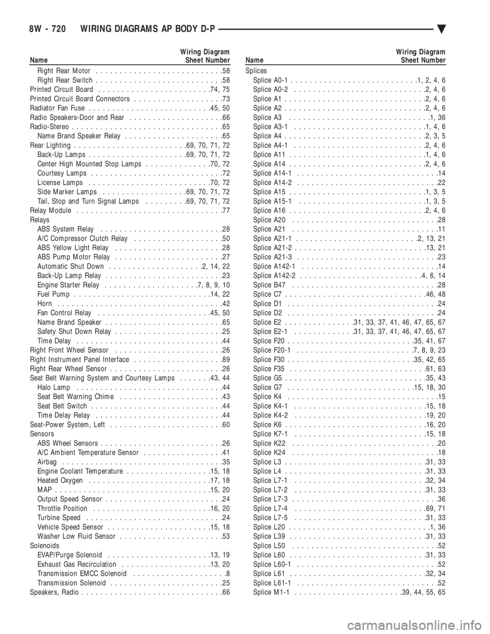
Wiring Diagram
Name Sheet Number
Right Rear Motor ...........................58
Right Rear Switch ...........................58
Printed Circuit Board ....................... .74, 75
Printed Circuit Board Connectors ...................73
Radiator Fan Fuse ......................... .45, 50
Radio Speakers-Door and Rear ....................66
Radio-Stereo ................................65
Name Brand Speaker Relay .....................65
Rear Lighting ....................... .69, 70, 71, 72
Back-Up Lamps .................... .69, 70, 71, 72
Center High Mounted Stop Lamps ..............70, 72
Courtesy Lamps ............................72
License Lamps ......................... .70, 72
Side Marker Lamps ................. .69, 70, 71, 72
Tail, Stop and Turn Signal Lamps .........69, 70, 71, 72
Relay Module ...............................77
Relays ABS System Relay ..........................28
A/C Compressor Clutch Relay ...................50
ABS Yellow Light Relay .......................28
ABS Pump Motor Relay .......................27
Automatic Shut Down ....................2,14,22
Back-Up Lamp Relay .........................23
Engine Starter Relay ....................7,8,9,10
Fuel Pump ............................ .14, 22
Horn ...................................42
Fan Control Relay ....................... .45, 50
Name Brand Speaker .........................65
Safety Shut Down Relay .......................25
Time Delay ...............................44
Right Front Wheel Sensor .......................26
Right Instrument Panel Interface ...................89
Right Rear Wheel Sensor ........................26
Seat Belt Warning System and Courtesy Lamps .......43, 44
Halo Lamp ...............................44
Seat Belt Warning Chime ......................43
Seat Belt Switch ............................44
Time Delay Relay ...........................44
Seat-Power System, Left ........................60
Sensors ABS Wheel Sensors ..........................26
A/C Ambient Temperature Sensor .................41
Airbag ..................................35
Engine Coolant Temperature ..................15, 18
Heated Oxygen ......................... .17, 18
MAP ................................ .15, 20
Output Speed Sensor .........................24
Throttle Position ........................ .16, 20
Turbine Speed .............................24
Vehicle Speed Sensor ..................... .15, 18
Washer Low Fluid Sensor ......................53
Solenoids EVAP/Purge Solenoid ..................... .13, 19
Exhaust Gas Recirculation .................. .13, 20
Transmission EMCC Solenoid ....................8
Transmission Solenoid ........................25
Speakers, Radio ..............................66Wiring Diagram
Name Sheet Number
Splices Splice A0-1 ...........................1,2,4,6
Splice A0-2 ............................2,4,6
Splice A1 ..............................2,4,6
Splice A2 ..............................2,4,6
Splice A3 ..............................1,36
Splice A3-1 ............................1,4,6
Splice A4 ..............................2,3,5
Splice A4-1 ............................2,4,6
Splice A11 .............................1,4,6
Splice A14 .............................2,4,6
Splice A14-1 ..............................14
Splice A14-2 ..............................22
Splice A15 .............................1,3,5
Splice A15-1 ...........................1,3,5
Splice A16 .............................2,4,6
Splice A20 ...............................28
Splice A21 ...............................11
Splice A21-1 ..........................2,13,21
Splice A21-2 ........................... .13, 21
Splice A21-3 ..............................23
Splice A142-1 .............................14
Splice A142-2 ..........................4,6,14
Splice B47 ...............................28
Splice C7 ............................. .46, 48
Splice D1 ................................24
Splice D2 ................................24
Splice E2 .............. .31, 33, 37, 41, 46, 47, 65, 67
Splice E2-1 ............ .31, 33, 37, 41, 46, 47, 65, 67
Splice F20 .......................... .35, 41, 67
Splice F20-1 .........................7,8,9,23
Splice F30 .......................... .35, 42, 65
Splice F35 ............................ .61, 63
Splice G5 ............................. .35, 43
Splice G7 .......................... .15, 18, 30
Splice K4 ................................15
Splice K4-1 ........................... .15, 18
Splice K4-2 ........................... .19, 20
Splice K6 ............................. .16, 20
Splice K7-1 ........................... .15, 18
Splice K22 ...............................20
Splice K24 ...............................18
Splice L3 ............................. .31, 33
Splice L4 ............................. .31, 33
Splice L7-1 ........................... .32, 34
Splice L7-2 ........................... .31, 33
Splice L7-3 ...............................36
Splice L7-4 ........................... .69, 71
Splice L7-5 ........................... .31, 33
Splice L20 ..............................1,36
Splice L39 ............................ .31, 33
Splice L50 ...............................52
Splice L60 ............................ .31, 33
Splice L60-1 ..............................52
Splice L61 ............................ .32, 34
Splice L61-1 ..............................52
Splice M1-1 ...................... .39, 44, 55, 65
8W - 720 WIRING DIAGRAMS AP BODY D-P Ä
Page 1471 of 2438
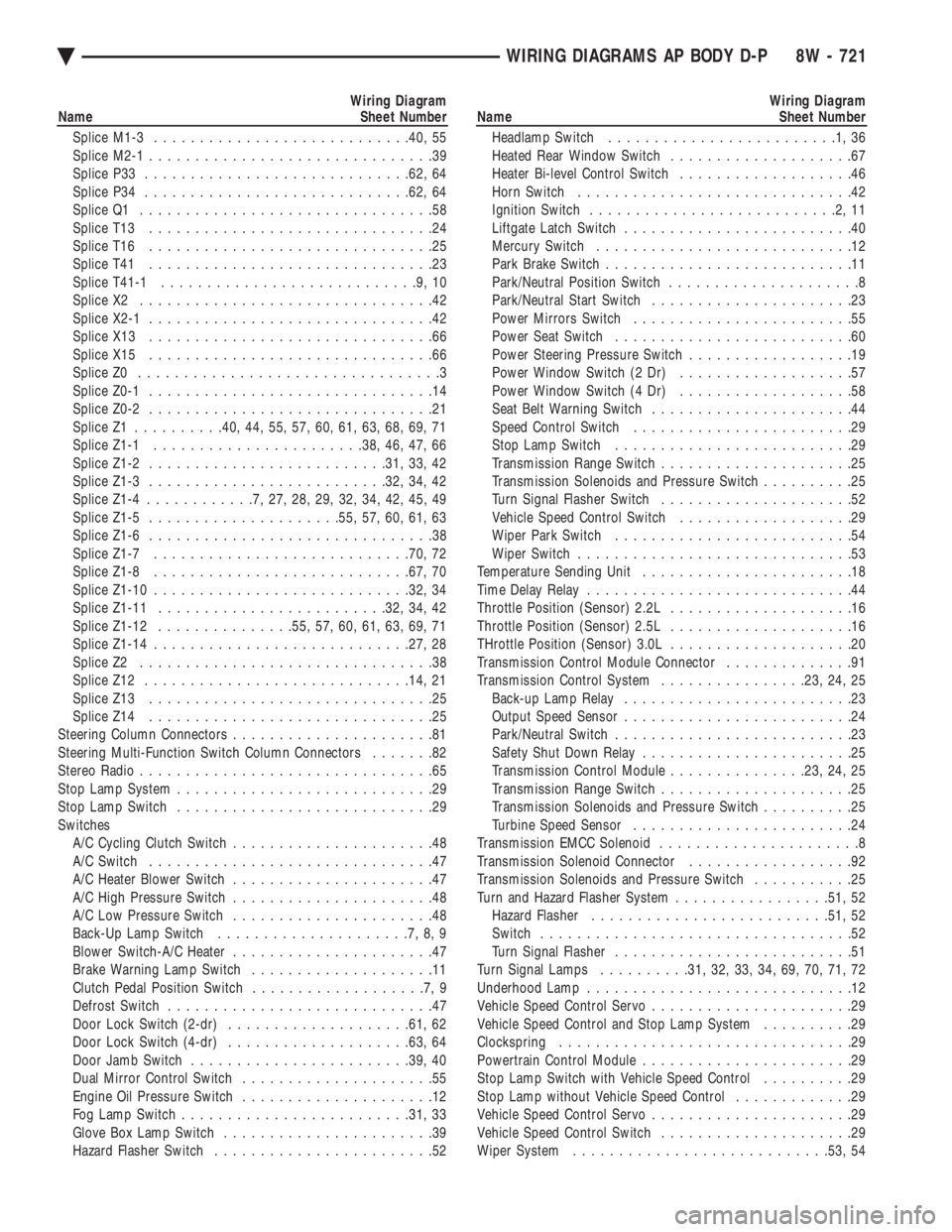
Wiring Diagram
Name Sheet Number
Splice M1-3 ........................... .40, 55
Splice M2-1 ...............................39
Splice P33 ............................ .62, 64
Splice P34 ............................ .62, 64
Splice Q1 ................................58
Splice T13 ...............................24
Splice T16 ...............................25
Splice T41 ...............................23
Splice T41-1 ............................9,10
Splice X2 ................................42
Splice X2-1 ...............................42
Splice X13 ...............................66
Splice X15 ...............................66
Splice Z0 .................................3
Splice Z0-1 ...............................14
Splice Z0-2 ...............................21
Splice Z1 ......... .40, 44, 55, 57, 60, 61, 63, 68, 69, 71
Splice Z1-1 ...................... .38, 46, 47, 66
Splice Z1-2 ......................... .31, 33, 42
Splice Z1-3 ......................... .32, 34, 42
Splice Z1-4 ............7,27,28,29,32,34,42,45,49
Splice Z1-5 .................... .55, 57, 60, 61, 63
Splice Z1-6 ...............................38
Splice Z1-7 ........................... .70, 72
Splice Z1-8 ........................... .67, 70
Splice Z1-10 ........................... .32, 34
Splice Z1-11 ........................ .32, 34, 42
Splice Z1-12 .............. .55, 57, 60, 61, 63, 69, 71
Splice Z1-14 ........................... .27, 28
Splice Z2 ................................38
Splice Z12 ............................ .14, 21
Splice Z13 ...............................25
Splice Z14 ...............................25
Steering Column Connectors ......................81
Steering Multi-Function Switch Column Connectors .......82
Stereo Radio ................................65
Stop Lamp System ............................29
Stop Lamp Switch ............................29
Switches A/C Cycling Clutch Switch ......................48
A/C Switch ...............................47
A/C Heater Blower Switch ......................47
A/C High Pressure Switch ......................48
A/C Low Pressure Switch ......................48
Back-Up Lamp Switch .....................7,8,9
Blower Switch-A/C Heater ......................47
Brake Warning Lamp Switch ....................11
Clutch Pedal Position Switch ...................7,9
Defrost Switch .............................47
Door Lock Switch (2-dr) ................... .61, 62
Door Lock Switch (4-dr) ................... .63, 64
Door Jamb Switch ....................... .39, 40
Dual Mirror Control Switch .....................55
Engine Oil Pressure Switch .....................12
Fog Lamp Switch ........................ .31, 33
Glove Box Lamp Switch .......................39
Hazard Flasher Switch ........................52Wiring Diagram
Name Sheet Number
Headlamp Switch .........................1,36
Heated Rear Window Switch ....................67
Heater Bi-level Control Switch ...................46
Horn Switch ..............................42
Ignition Switch ...........................2,11
Liftgate Latch Switch .........................40
Mercury Switch ............................12
Park Brake Switch ...........................11
Park/Neutral Position Switch .....................8
Park/Neutral Start Switch ......................23
Power Mirrors Switch ........................55
Power Seat Switch ..........................60
Power Steering Pressure Switch ..................19
Power Window Switch (2 Dr) ...................57
Power Window Switch (4 Dr) ...................58
Seat Belt Warning Switch ......................44
Speed Control Switch ........................29
Stop Lamp Switch ..........................29
Transmission Range Switch .....................25
Transmission Solenoids and Pressure Switch ..........25
Turn Signal Flasher Switch .....................52
Vehicle Speed Control Switch ...................29
Wiper Park Switch ..........................54
Wiper Switch ..............................53
Temperature Sending Unit .......................18
Time Delay Relay .............................44
Throttle Position (Sensor) 2.2L ....................16
Throttle Position (Sensor) 2.5L ....................16
THrottle Position (Sensor) 3.0L ....................20
Transmission Control Module Connector ..............91
Transmission Control System ................23, 24, 25
Back-up Lamp Relay .........................23
Output Speed Sensor .........................24
Park/Neutral Switch ..........................23
Safety Shut Down Relay .......................25
Transmission Control Module ...............23, 24, 25
Transmission Range Switch .....................25
Transmission Solenoids and Pressure Switch ..........25
Turbine Speed Sensor ........................24
Transmission EMCC Solenoid ......................8
Transmission Solenoid Connector ..................92
Transmission Solenoids and Pressure Switch ...........25
Turn and Hazard Flasher System .................51, 52
Hazard Flasher ......................... .51, 52
Switch ..................................52
Turn Signal Flasher ..........................51
Turn Signal Lamps ..........31, 32, 33, 34, 69, 70, 71, 72
Underhood Lamp .............................12
Vehicle Speed Control Servo ......................29
Vehicle Speed Control and Stop Lamp System ..........29
Clockspring ................................29
Powertrain Control Module .......................29
Stop Lamp Switch with Vehicle Speed Control ..........29
Stop Lamp without Vehicle Speed Control .............29
Vehicle Speed Control Servo ......................29
Vehicle Speed Control Switch .....................29
Wiper System ........................... .53, 54
Ä WIRING DIAGRAMS AP BODY D-P 8W - 721
Page 1579 of 2438
² Drive shaft distress: See Driveshafts in Suspension,
Group 2.
² Any front end structural damage (after repair).
² Insulator replacement.
ENGINE MOUNT INSULATOR ADJUSTMENT
(1) Remove the load on the engine motor mounts by
carefully supporting the engine and transmission as-
sembly with a floor jack. (2) Loosen the right engine mount insulator vertical
fasteners, and the front engine mount bracket to front
crossmember screws and nuts. Left engine mount insulator is sleeved over
shaft and long support bolt to provide lateral
movement adjustment with engine weight re-
moved or not. (3) Pry the engine right or left as required to achieve
the proper drive shaft assembly length. See Drive
Shaft in Suspension Group 2 for driveshaft identifica-
tion and related assembly length measuring. (4) Tighten right engine mount insulator vertical
bolts to 68 N Im (50 ft. lbs.). Then tighten front engine
mount screws and nuts to 54 N Im (40 ft. lbs.) and
center left engine mount insulator. (5) Recheck drive shaft length.
ENGINE ASSEMBLY
REMOVAL
(1) Disconnect battery.
(2) Scribe hood hinge outline on hood and remove
hood. (3) Drain cooling system.
(4) Remove hoses from radiator and engine.
(5) Remove radiator and fan assembly.
(6) Remove air cleaner and hoses.
(7) Remove air conditioning compressor mounting
bolts and set compressor aside, if equipped. (8) Remove power steering pump mounting bolts
and set pump aside (9) Remove oil filter.
(10) Disconnect fuel line, heater hose and acceler-
ator cable. (11) Disconnect all electrical connections and har-
nesses at throttle body and engine. (12) Manual Transmission
(a) Disconnect clutch cable.
(b) Remove transmission case lower cover.
(c) Disconnect exhaust pipe at manifold.
(d) Disconnect starter and lay aside.
(e) Install transmission holding fixture.
(13) Automatic Transmission
(a) Disconnect exhaust pipe at manifold.
(b) Disconnect starter and lay aside.
(c) Remove transmission case lower cover.
(d) Mark flex plate to torque converter.
(e) Remove screws holding torque converter to
flex plate.
(14) Attach C clamp on front bottom of torque con-
verter housing to prevent torque converter from com-
ing out. (15) Install transmission holding fixture.
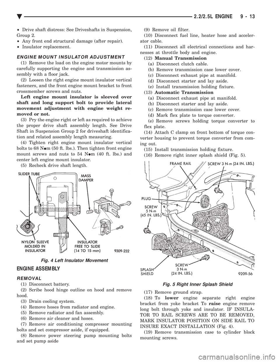
(16) Remove right inner splash shield (Fig. 5).
(17) Remove ground strap.
(18) To lowerengine separate right engine
bracket from yoke bracket To raiseengine remove
long bolt through yoke and insulator. IF INSULA-
TOR TO RAIL SCREWS ARE TO BE REMOVED,
MARK INSULATOR POSITION ON SIDE RAIL TO
INSURE EXACT INSTALLATION (Fig. 4). (19) Remove transmission case to cylinder block
mounting screws.Fig. 5 Right Inner Splash Shield
Fig. 4 Left Insulator Movement
Ä 2.2/2.5L ENGINE 9 - 13
Page 1580 of 2438
CAUTION: Make sure clutch cable has been discon-
nected. (20) Remove front engine mount screw and nut.
(21) Remove manual transmission damper.
(22) Remove left insulator through bolt from inside
wheelhouse or insulator bracket to transmission
screws. (23) Remove engine from vehicle.
INSTALLATION
(1) Install hoist to the engine and lower engine
into the engine compartment. SEE: ENGINE MOUNT RUBBER INSULATORS,
THIS GROUP. (2) Align engine mounts and install but do not
tighten until all mounting bolts have been installed.
(3) Install transmission case to cylinder block
mounting screws. Tighten to 95 N Im (70 ft. lbs.)
torque. (4) Remove engine hoist and transmission holding
fixture. (5) Install ground strap.
(6) Install right inner splash shield.
(7) Connect starter. See Electrical Group 8 for in-
stallation. (8) Connect exhaust system. See Exhaust Systems
Group 11 for installation. (9) Manual Transmission: Install transmission
case lower cover. Automatic Transmission: Remove C clamp from
torque converter housing. Align flexplate to torque
converter and install mounting screws. Tighten to 75
N Im (55 ft. lbs.) torque.
(10) Manual Transmission: Connect clutch cable.
See Clutch Group 6. (11) Install power steering pump. Refer to Cooling
System Group 7, Accessory Drive Section for belt
tension adjustment. (12) Connect fuel line, heater hose, and accelerator
cable. (13) Connect all electrical connections and har-
nesses at throttle body and engine. (14) Install oil filter. Fill engine crankcase with
proper oil to correct level. (15) Install air conditioning compressor (if
equipped). See Heater and Air Conditioning, Group
24 for installation. (16) Install air cleaner and hoses.
(17) Install radiator and shroud assembly . Install
radiator hoses. Fill cooling system. See Cooling Sys-
tem Group 7 for filling procedure. (18) Install hood.
(19) Connect battery.
(20) Start engine and run until operating temper-
ature is reached. (21) Adjust transmission linkage, if necessary.
SOLID MOUNT COMPRESSOR BRACKET SERVICE
When service procedures require solid mount
bracket removal and installation for example: cylin-
der head removal, etc., it is important that bracket
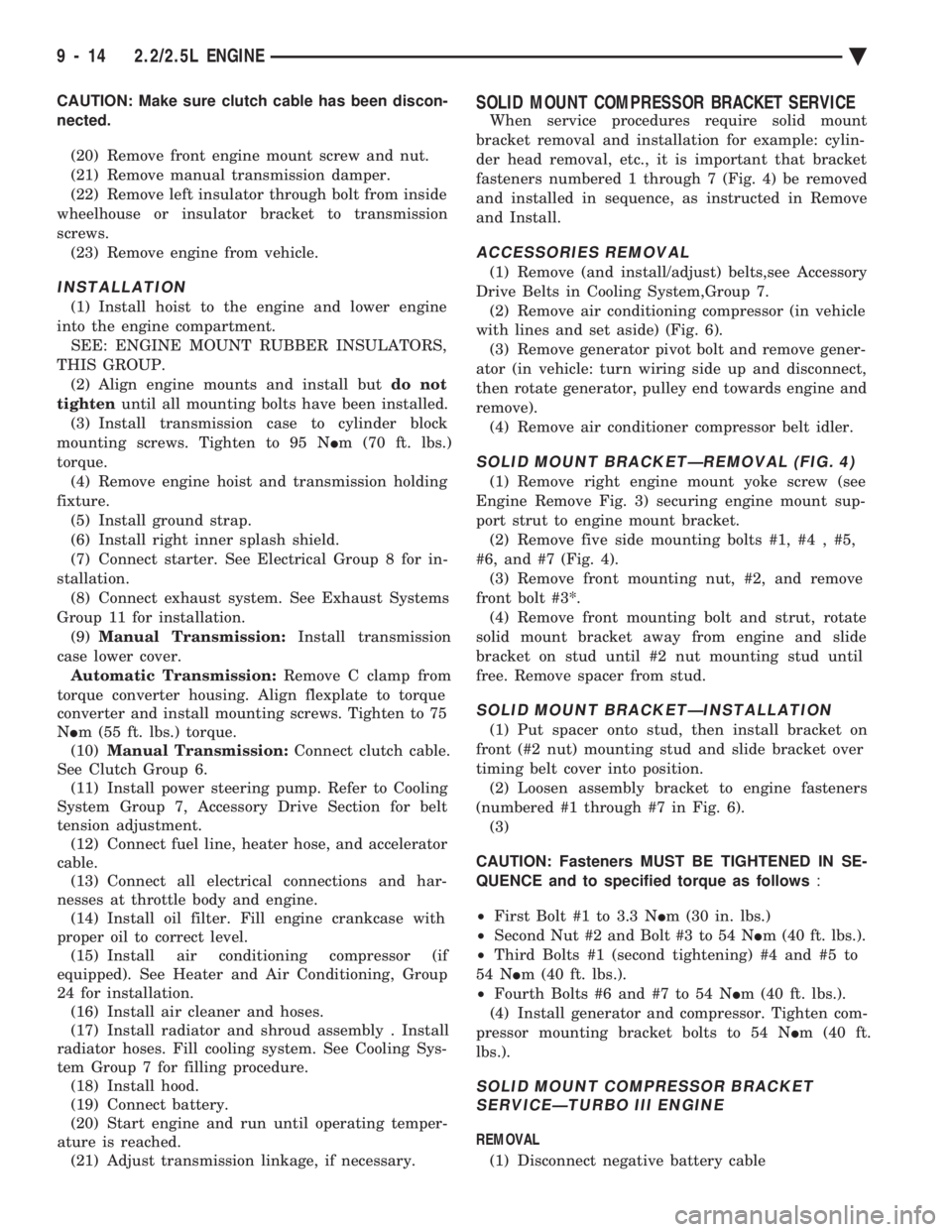
fasteners numbered 1 through 7 (Fig. 4) be removed
and installed in sequence, as instructed in Remove
and Install.
ACCESSORIES REMOVAL
(1) Remove (and install/adjust) belts,see Accessory
Drive Belts in Cooling System,Group 7. (2) Remove air conditioning compressor (in vehicle
with lines and set aside) (Fig. 6). (3) Remove generator pivot bolt and remove gener-
ator (in vehicle: turn wiring side up and disconnect,
then rotate generator, pulley end towards engine and
remove). (4) Remove air conditioner compressor belt idler.
SOLID MOUNT BRACKETÐREMOVAL (FIG. 4)
(1) Remove right engine mount yoke screw (see
Engine Remove Fig. 3) securing engine mount sup-
port strut to engine mount bracket. (2) Remove five side mounting bolts #1, #4 , #5,
#6, and #7 (Fig. 4). (3) Remove front mounting nut, #2, and remove
front bolt #3*. (4) Remove front mounting bolt and strut, rotate
solid mount bracket away from engine and slide
bracket on stud until #2 nut mounting stud until
free. Remove spacer from stud.
SOLID MOUNT BRACKETÐINSTALLATION
(1) Put spacer onto stud, then install bracket on
front (#2 nut) mounting stud and slide bracket over
timing belt cover into position. (2) Loosen assembly bracket to engine fasteners
(numbered #1 through #7 in Fig. 6). (3)
CAUTION: Fasteners MUST BE TIGHTENED IN SE-
QUENCE and to specified torque as follows :
² First Bolt #1 to 3.3 N Im (30 in. lbs.)
² Second Nut #2 and Bolt #3 to 54 N Im (40 ft. lbs.).
² Third Bolts #1 (second tightening) #4 and #5 to
54 N Im (40 ft. lbs.).
² Fourth Bolts #6 and #7 to 54 N Im (40 ft. lbs.).
(4) Install generator and compressor. Tighten com-
pressor mounting bracket bolts to 54 N Im (40 ft.
lbs.).
SOLID MOUNT COMPRESSOR BRACKET SERVICEÐTURBO III ENGINE
REMOVAL
(1) Disconnect negative battery cable
9 - 14 2.2/2.5L ENGINE Ä
Page 1764 of 2438
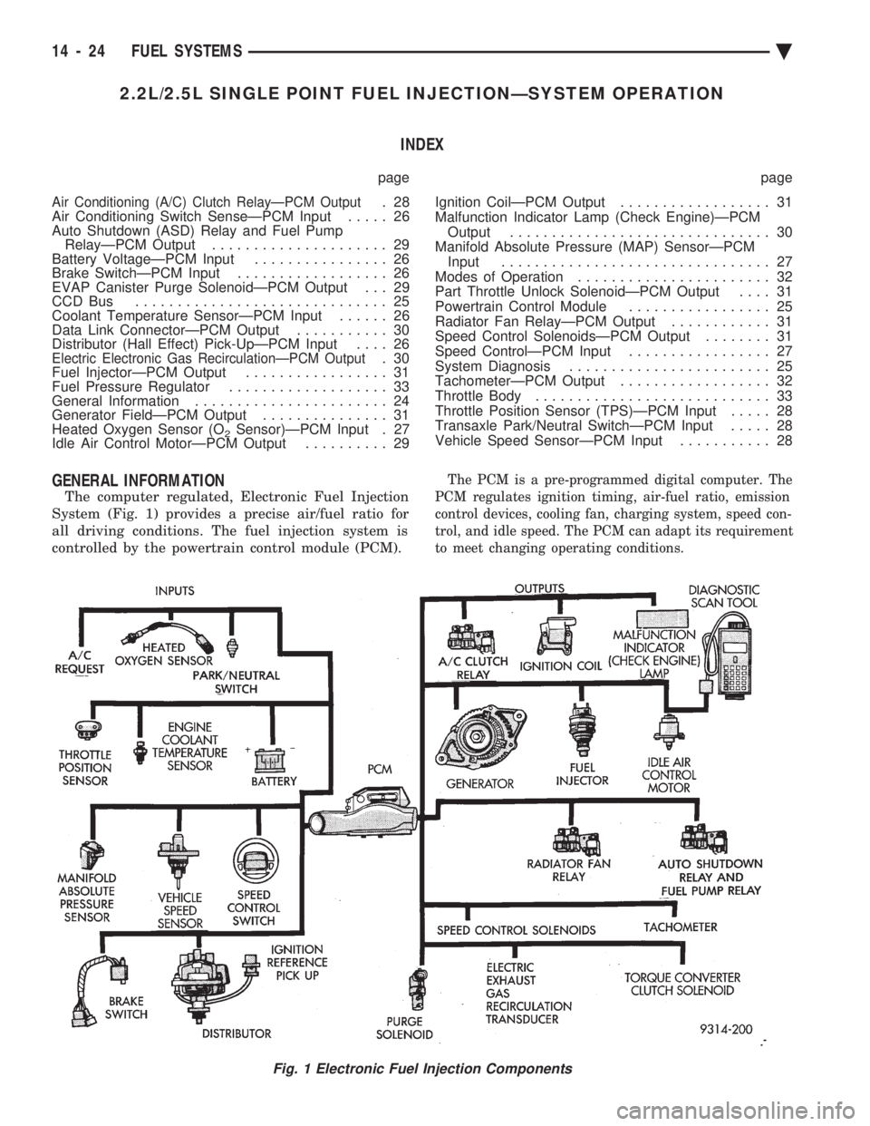
2.2L/2.5L SINGLE POINT FUEL INJECTIONÐSYSTEM OPERATION INDEX
page page
Air Conditioning (A/C) Clutch RelayÐPCM Output.28
Air Conditioning Switch SenseÐPCM Input ..... 26
Auto Shutdown (ASD) Relay and Fuel Pump RelayÐPCM Output ..................... 29
Battery VoltageÐPCM Input ................ 26
Brake SwitchÐPCM Input .................. 26
EVAP Canister Purge SolenoidÐPCM Output . . . 29
CCD Bus .............................. 25
Coolant Temperature SensorÐPCM Input ...... 26
Data Link ConnectorÐPCM Output ........... 30
Distributor (Hall Effect) Pick-UpÐPCM Input .... 26
Electric Electronic Gas RecirculationÐPCM Output.30
Fuel InjectorÐPCM Output ................. 31
Fuel Pressure Regulator ................... 33
General Information ....................... 24
Generator FieldÐPCM Output ............... 31
Heated Oxygen Sensor (O
2Sensor)ÐPCM Input . 27
Idle Air Control MotorÐPCM Output .......... 29 Ignition CoilÐPCM Output
.................. 31
Malfunction Indicator Lamp (Check Engine)ÐPCM Output ............................... 30
Manifold Absolute Pressure (MAP) SensorÐPCM Input ................................ 27
Modes of Operation ....................... 32
Part Throttle Unlock SolenoidÐPCM Output .... 31
Powertrain Control Module ................. 25
Radiator Fan RelayÐPCM Output ............ 31
Speed Control SolenoidsÐPCM Output ........ 31
Speed ControlÐPCM Input ................. 27
System Diagnosis ........................ 25
TachometerÐPCM Output .................. 32
Throttle Body ............................ 33
Throttle Position Sensor (TPS)ÐPCM Input ..... 28
Transaxle Park/Neutral SwitchÐPCM Input ..... 28
Vehicle Speed SensorÐPCM Input ........... 28
GENERAL INFORMATION
The computer regulated, Electronic Fuel Injection
System (Fig. 1) provides a precise air/fuel ratio for
all driving conditions. The fuel injection system is
controlled by the powertrain control module (PCM).
The PCM is a pre-programmed digital computer. The
PCM regulates ignition timing, air-fuel ratio, emission
control devices, cooling fan, charging system, speed con-
trol, and idle speed. The PCM can adapt its requirement
to meet changing operating conditions.
Fig. 1 Electronic Fuel Injection Components
14 - 24 FUEL SYSTEMS Ä
Page 1765 of 2438
Various sensors provide the inputs necessary for
the PCM to correctly regulate fuel flow at the fuel
injector. These include the manifold absolute pres-
sure, throttle position, oxygen sensor, coolant tem-
perature, and vehicle speed sensors. In addition to
the sensors, various switches and relays provide im-
portant information and system control. The inputs
include the park/neutral switch and air conditioning
clutch switch. The outputs include the auto shutdown
relay and fuel pump relay. All inputs to the PCM are converted into signals.
Based on these inputs the PCM adjusts air-fuel ratio,
ignition timing and other controlled outputs. The
PCM adjusts the air-fuel ratio by changing the injec-
tor pulse width. Injector pulse width is the period of
time the injector is energized.
SYSTEM DIAGNOSIS
The PCM tests many of its own input and output
circuits. If a fault is found in a major system, the in-
formation is stored in memory. Technicians can dis-
play fault information through the instrument panel
Malfunction Indicator lamp (instrument panel Check
Engine lamp) or by connecting the DRBII scan tool.
For diagnostic trouble code information, refer to On
Board Diagnostics in 2.2L/2.5L Single Point Fuel In-
jectionÐGeneral Diagnosis section of this group.
CCD BUS
Various modules exchange information through a
communications port called the CCD Bus. The pow-
ertrain control module (PCM) transmits vehicle load
data on the CCD Bus.
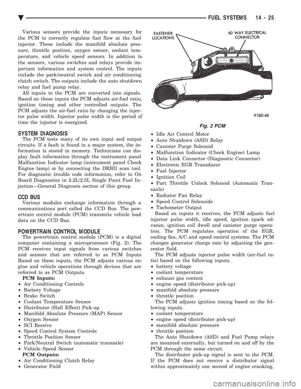
POWERTRAIN CONTROL MODULE
The powertrain control module (PCM) is a digital
computer containing a microprocessor (Fig. 2). The
PCM receives input signals from various switches
and sensors that are referred to as PCM Inputs.
Based on these inputs, the PCM adjusts various en-
gine and vehicle operations through devices that are
referred to as PCM Outputs. PCM Inputs:
² Air Conditioning Controls
² Battery Voltage
² Brake Switch
² Coolant Temperature Sensor
² Distributor (Hall Effect) Pick-up
² Manifold Absolute Pressure (MAP) Sensor
² Oxygen Sensor
² SCI Receive
² Speed Control System Controls
² Throttle Position Sensor
² Park/Neutral Switch (automatic transaxle)
² Vehicle Speed Sensor
PCM Outputs:
² Air Conditioning Clutch Relay
² Generator Field ²
Idle Air Control Motor
² Auto Shutdown (ASD) Relay
² Canister Purge Solenoid
² Malfunction Indicator (Check Engine) Lamp
² Data Link Connector (Diagnostic Connector)
² Electronic EGR Transducer
² Fuel Injector
² Ignition Coil
² Part Throttle Unlock Solenoid (Automatic Tran-
saxle)
² Radiator Fan Relay
² Speed Control Solenoids
² Tachometer Output
Based on inputs it receives, the PCM adjusts fuel
injector pulse width, idle speed, ignition spark ad-
vance, ignition coil dwell and canister purge opera-
tion. The PCM regulates operation of the EGR,
cooling fan, A/C and speed control systems. The PCM
changes generator charge rate by adjusting the gen-
erator field. The PCM adjusts injector pulse width (air-fuel ra-
tio) based on the following inputs.
² battery voltage
² coolant temperature
² exhaust gas content
² engine speed (distributor pick-up)
² manifold absolute pressure
² throttle position
The PCM adjusts ignition timing based on the fol-
lowing inputs.
² coolant temperature
² engine speed (distributor pick-up)
² manifold absolute pressure
² throttle position
The Auto Shutdown (ASD) and Fuel Pump relays
are mounted externally, but turned on and off by the
PCM through the same circuit. The distributor pick-up signal is sent to the PCM.
If the PCM does not receive a distributor signal
within approximately one second of engine cranking,
Fig. 2 PCM
Ä FUEL SYSTEMS 14 - 25
Page 1766 of 2438
it de-activates the ASD relay and fuel pump relay.
When these relays are deactivated, power is shut off
from the fuel injector, fuel pump, ignition coil, and
oxygen sensor heater element. The PCM contains a voltage converter that
changes battery voltage to a regulated 8.0 volts to
power the distributor pick-up and vehicle speed sen-
sor. The PCM also provides a 5.0 volts supply for the
coolant temperature sensor, manifold absolute pres-
sure sensor and throttle position sensor.
AIR CONDITIONING SWITCH SENSEÐPCM INPUT
ALL VEHICLES EXCEPT AC-BODY
When the air conditioning or defrost switch is put
in the ON position and the low pressure and high
pressure switches are closed, the PCM receives an in-
put indicating that the air conditioning has been se-
lected. After receiving this input, the PCM activates
the A/C compressor clutch by grounding the A/C
clutch relay. The PCM also adjusts idle speed to a
scheduled RPM to compensate for increased engine
load.
AC-BODY VEHICLES
When the air conditioning or defrost switch is put
in the ON position and the low pressure switch, high
pressure switch and electronic cycling switch close,
the PCM receives an air conditioning select input.
After receiving this input, the PCM activates the
A/C compressor clutch by grounding the A/C com-
pressor clutch relay. The PCM also adjusts idle speed
to a scheduled RPM to compensate for increased en-
gine load.
BATTERY VOLTAGEÐPCM INPUT
The PCM monitors the battery voltage input to de-
termine fuel injector pulse width and generator field
control. If battery voltage is low, the PCM increases
injector pulse width.
BRAKE SWITCHÐPCM INPUT
When the brake switch is activated, the PCM re-
ceives an input indicating that the brakes are being
applied. After receiving the input, the PCM vents the
speed control servo. Venting the servo turns the
speed control system off.
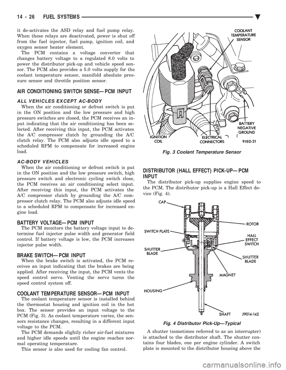
COOLANT TEMPERATURE SENSORÐPCM INPUT
The coolant temperature sensor is installed behind
the thermostat housing and ignition coil in the hot
box. The sensor provides an input voltage to the
PCM (Fig. 3). As coolant temperature varies, the sen-
sors resistance changes, resulting in a different input
voltage to the PCM. The PCM demands slightly richer air-fuel mixtures
and higher idle speeds until the engine reaches nor-
mal operating temperature. This sensor is also used for cooling fan control.
DISTRIBUTOR (HALL EFFECT) PICK-UPÐPCM
INPUT
The distributor pick-up supplies engine speed to
the PCM. The distributor pick-up is a Hall Effect de-
vice (Fig. 4).
A shutter (sometimes referred to as an interrupter)
is attached to the distributor shaft. The shutter con-
tains four blades, one per engine cylinder. A switch
plate is mounted to the distributor housing above the
Fig. 3 Coolant Temperature Sensor
Fig. 4 Distributor Pick-UpÐTypical
14 - 26 FUEL SYSTEMS Ä
Page 1768 of 2438
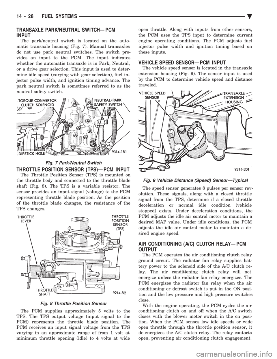
TRANSAXLE PARK/NEUTRAL SWITCHÐPCM
INPUT
The park/neutral switch is located on the auto-
matic transaxle housing (Fig. 7). Manual transaxles
do not use park neutral switches. The switch pro-
vides an input to the PCM. The input indicates
whether the automatic transaxle is in Park, Neutral,
or a drive gear selection. This input is used to deter-
mine idle speed (varying with gear selection), fuel in-
jector pulse width, and ignition timing advance. The
park neutral switch is sometimes referred to as the
neutral safety switch.
THROTTLE POSITION SENSOR (TPS)ÐPCM INPUT
The Throttle Position Sensor (TPS) is mounted on
the throttle body and connected to the throttle blade
shaft (Fig. 8). The TPS is a variable resistor. The
sensor provides an input signal (voltage) to the PCM
representing throttle blade position. As the position
of the throttle blade changes, the resistance of the
TPS changes.
The PCM supplies approximately 5 volts to the
TPS. The TPS output voltage (input signal to the
PCM) represents the throttle blade position. The
PCM receives an input signal voltage from the TPS
varying in an approximate range of from 1 volt at
minimum throttle opening (idle) to 4 volts at wide open throttle. Along with inputs from other sensors,
the PCM uses the TPS input to determine current
engine operating conditions. The PCM adjusts fuel
injector pulse width and ignition timing based on
these inputs.
VEHICLE SPEED SENSORÐPCM INPUT
The vehicle speed sensor is located in the transaxle
extension housing (Fig. 9). The sensor input is used
by the PCM to determine vehicle speed and distance
traveled.
The speed sensor generates 8 pulses per sensor rev-
olution. These signals, along with a closed throttle
signal from the TPS, determine if a closed throttle
deceleration or normal idle condition (vehicle
stopped) exists. Under deceleration conditions, the
PCM adjusts the idle air control motor to maintain a
desired MAP value. Under idle conditions, the PCM
adjusts the idle air control motor to maintain a de-
sired engine speed.
AIR CONDITIONING (A/C) CLUTCH RELAYÐPCM
OUTPUT
The PCM operates the air conditioning clutch relay
ground circuit. The radiator fan relay supplies bat-
tery power to the solenoid side of the A/C clutch re-
lay. The air conditioning clutch relay will not
energize unless the radiator fan relay energizes. The
PCM energizes the radiator fan relay when the air
conditioning or defrost switch is put in the ON posi-
tion and the low pressure and high pressure switches
close. With the engine operating, the PCM cycles the air
conditioning clutch on and off when the A/C switch
closes with the blower motor switch in the on posi-
tion. When the PCM senses low idle speeds or wide
open throttle through the throttle position sensor, it
de-energizes the A/C clutch relay. The relay contacts
open, preventing air conditioning clutch engagement.
Fig. 7 Park/Neutral Switch
Fig. 8 Throttle Position Sensor
Fig. 9 Vehicle Distance (Speed) SensorÐTypical
14 - 28 FUEL SYSTEMS Ä
Page 1769 of 2438
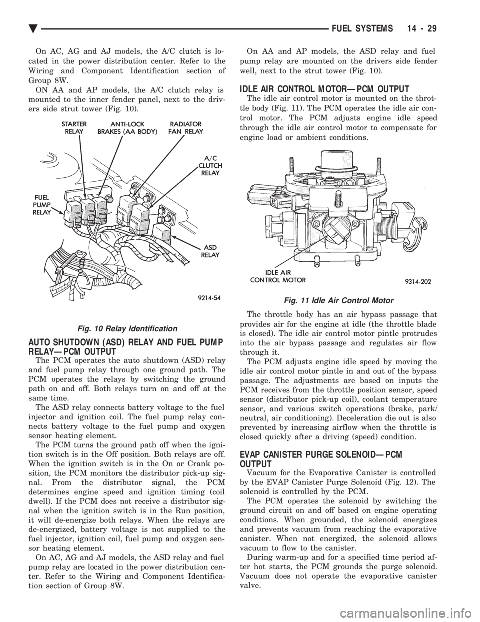
On AC, AG and AJ models, the A/C clutch is lo-
cated in the power distribution center. Refer to the
Wiring and Component Identification section of
Group 8W. ON AA and AP models, the A/C clutch relay is
mounted to the inner fender panel, next to the driv-
ers side strut tower (Fig. 10).
AUTO SHUTDOWN (ASD) RELAY AND FUEL PUMP
RELAYÐPCM OUTPUT
The PCM operates the auto shutdown (ASD) relay
and fuel pump relay through one ground path. The
PCM operates the relays by switching the ground
path on and off. Both relays turn on and off at the
same time. The ASD relay connects battery voltage to the fuel
injector and ignition coil. The fuel pump relay con-
nects battery voltage to the fuel pump and oxygen
sensor heating element. The PCM turns the ground path off when the igni-
tion switch is in the Off position. Both relays are off.
When the ignition switch is in the On or Crank po-
sition, the PCM monitors the distributor pick-up sig-
nal. From the distributor signal, the PCM
determines engine speed and ignition timing (coil
dwell). If the PCM does not receive a distributor sig-
nal when the ignition switch is in the Run position,
it will de-energize both relays. When the relays are
de-energized, battery voltage is not supplied to the
fuel injector, ignition coil, fuel pump and oxygen sen-
sor heating element. On AC, AG and AJ models, the ASD relay and fuel
pump relay are located in the power distribution cen-
ter. Refer to the Wiring and Component Identifica-
tion section of Group 8W. On AA and AP models, the ASD relay and fuel
pump relay are mounted on the drivers side fender
well, next to the strut tower (Fig. 10).
IDLE AIR CONTROL MOTORÐPCM OUTPUT
The idle air control motor is mounted on the throt-
tle body (Fig. 11). The PCM operates the idle air con-
trol motor. The PCM adjusts engine idle speed
through the idle air control motor to compensate for
engine load or ambient conditions.
The throttle body has an air bypass passage that
provides air for the engine at idle (the throttle blade
is closed). The idle air control motor pintle protrudes
into the air bypass passage and regulates air flow
through it. The PCM adjusts engine idle speed by moving the
idle air control motor pintle in and out of the bypass
passage. The adjustments are based on inputs the
PCM receives from the throttle position sensor, speed
sensor (distributor pick-up coil), coolant temperature
sensor, and various switch operations (brake, park/
neutral, air conditioning). Deceleration die out is also
prevented by increasing airflow when the throttle is
closed quickly after a driving (speed) condition.
EVAP CANISTER PURGE SOLENOIDÐPCM
OUTPUT
Vacuum for the Evaporative Canister is controlled
by the EVAP Canister Purge Solenoid (Fig. 12). The
solenoid is controlled by the PCM. The PCM operates the solenoid by switching the
ground circuit on and off based on engine operating
conditions. When grounded, the solenoid energizes
and prevents vacuum from reaching the evaporative
canister. When not energized, the solenoid allows
vacuum to flow to the canister. During warm-up and for a specified time period af-
ter hot starts, the PCM grounds the purge solenoid.
Vacuum does not operate the evaporative canister
valve.
Fig. 10 Relay Identification
Fig. 11 Idle Air Control Motor
Ä FUEL SYSTEMS 14 - 29
Page 1785 of 2438
SYSTEMS TEST
WARNING: APPLY PARKING BRAKE AND/OR
BLOCK WHEELS BEFORE PERFORMING A TEST
WITH THE ENGINE OPERATING.
OBTAINING DIAGNOSTIC TROUBLE CODES
(1) Connect DRBII scan tool to the data link con-
nector located in the engine compartment near the
powertrain control module (PCM). (2) Start the engine if possible, cycle the transaxle
selector and the A/Cswitch if applicable. Shut off
the engine. (3) Turn the ignition switch on, access Read Fault
Screen. Record all the fault messages shown on the
DRBII scan tool. Observe the malfunction indicator
lamp (check engine lamp on the instrument panel).
The lamp should light for 3 seconds then go out (bulb
check).
STATE DISPLAY TEST MODE
The switch inputs used by the powertrain control
module (PCM) have only two recognized states,
HIGH and LOW. For this reason, the PCM cannot
recognize the difference between a selected switch po-
sition versus an open circuit, a short circuit, or a de-
fective switch. If the change is displayed, it can be
assumed that the entire switch circuit to the PCM is
functional. From the state display screen access ei-
ther State Display Inputs and Outputs or State Dis-
play Sensors.
STATE DISPLAY INPUTS AND OUTPUTS
Connect the DRBII scan tool to the vehicle and ac-
cess the State Display screen. Then access Inputs and
Outputs. The following is a list of the engine control
system functions accessible through the Inputs and
Outputs screen. Park/Neutral Switch (automatic transaxle only)
Speed Control Resume
Brake Switch
Speed Control On/Off
Speed Control Set
A/C Switch Sense
S/C (Speed Control) Vent Solenoid
S/C (Speed Control) Vacuum Solenoid
Torque Converter Clutch Solenoid (3 speed auto-
matic transaxle)
A/C Clutch Relay
EGR Solenoid
Auto Shutdown Relay
Radiator Fan Relay
Purge Solenoid
Malfunction Indicator (Check Engine) Lamp
STATE DISPLAY SENSORS
Connect the DRBII scan tool to the vehicle and ac-
cess the State Display screen. Then access Sensor
Display. The following is a list of the engine control
system functions accessible through the Sensor Dis-
play screen. Oxygen Sensor Signal
Coolant Temperature
Coolant Temp Sensor
Throttle Position
Minimum Throttle
Battery Voltage
MAP Sensor Reading
Idle Air Control Motor Position
Added Adaptive Fuel
Adaptive Fuel Factor
Barometric Pressure
Min Airflow Idl Spd
Engine Speed
Fault #1 Key-On Info
Module Spark Advance
Speed Control Target
Fault #2 Key-On Info
Fault #3 Key-On Info
Speed Control Status
Charging System Goal
Theft Alarm Status
Speed Control Switch Voltage
Map Sensor Voltage
Vehicle Speed
Oxygen Sensor State
MAP Gauge Reading
Throttle Opening (percentage)
Total Spark Advance
CIRCUIT ACTUATION TEST MODE
The circuit actuation test mode checks for proper
operation of output circuits or devices which the pow-
ertrain control module (PCM) cannot internally rec-
ognize. The PCM can attempt to activate these
outputs and allow an observer to verify proper oper-
ation. Most of the tests provide an audible or visual
indication of device operation (click of relay contacts,
spray fuel, etc.). With the exception of an intermit-
tent condition, if a device functions properly during
its test, it can be assumed that the device, its associ-
ated wiring, and its driver circuit are in working or-
der.
OBTAINING CIRCUIT ACTUATION TEST
Connect the DRBII scan tool to the vehicle and ac-
cess the Actuators screen. The following is a list of
the engine control system functions accessible
through Actuators screens. Stop All Tests
Ignition Coil #1
Fuel Injector #1
Idle Air Control Motor Open/Close
Ä FUEL SYSTEMS 14 - 45