charging CHEVROLET DYNASTY 1993 Manual Online
[x] Cancel search | Manufacturer: CHEVROLET, Model Year: 1993, Model line: DYNASTY, Model: CHEVROLET DYNASTY 1993Pages: 2438, PDF Size: 74.98 MB
Page 2321 of 2438
(2) The appropriate Powertrain Diagnostic Proce-
dures Manual for diagnostic information. (3) The Compressor Clutch DiagnosisÐVariable
Displacement Compressor chart in this section. (4) On 2.2 L Turbo III engines, check for battery
voltage at the Thermal Limiter Switch located on the
compressor. If voltage is found at the cut-off and/or thermal
limiter switch, reconnect switch. Then check for bat-
tery voltage between the compressor clutch connector
terminals. If voltage is detected, perform A/C Clutch Coil
Tests. Refer to Clutch Coil Tests in this section.
CLUTCH COIL TESTS
(1) Verify battery state of charge. (Test indicator
in battery should be green). (2) Connect an ammeter (0-10 ampere scale) in se-
ries with the clutch coil terminal. Use a volt meter
(0-20 volt scale) with clip leads measuring voltage
across the battery and A/C clutch. (3) With A/C control in A/C mode and blower at
low speed, start the engine and run at normal idle. (4) The A/C clutch should engage immediately and
the clutch voltage should be within two volts of the
battery voltage. If the A/C clutch does not engage,
test the fusible link. (5) The A/C clutch coil is acceptable if the current
draw is 2.0 to 3.7 amperes at 11.5-12.5 volts at clutch
coil. This is with the work area temperature at 21ÉC
(70ÉF). If voltage is more than 12.5 volts, add electri-
cal loads by turning on electrical accessories until
voltage reads below 12.5 volts. If coil current reads zero, the coil is open and
should be replaced. If the ammeter reading is 4 am-
peres or more, the coil is shorted and should be re-
placed. If the coil voltage is not within two volts of
the battery voltage, test clutch coil feed circuit for
excessive voltage drop.
COMPRESSOR
The A/C compressor may be removed and posi-
tioned without discharging the refrigerant system.
Discharging is not necessary if removing the A/C
compressor clutch/coil assembly, engine, cylinder
head, or generator.
WARNING: REFRIGERANT PRESSURES REMAIN HIGH
EVEN THOUGH THE ENGINE MAY BE TURNED OFF.
BEFORE REMOVING A FULLY CHARGED COMPRES-
SOR, REVIEW THE SAFETY PRECAUTIONS AND
WARNINGS SECTION IN THIS GROUP. DO NOT TWIST
OR KINK THE REFRIGERANT LINES WHEN REMOV-
ING A FULLY CHARGED COMPRESSOR. SAFETY
GLASSES MUST BE WORN.
REMOVAL AND INSTALLATION
(1) Disconnect NEGATIVE battery cable.
(2) Loosen and remove drive belts (Refer to Group
7, Cooling System) and disconnect compressor clutch
wire lead. (3) Remove refrigerant lines from compressor (if
necessary). (4) Remove compressor attaching nuts and bolts
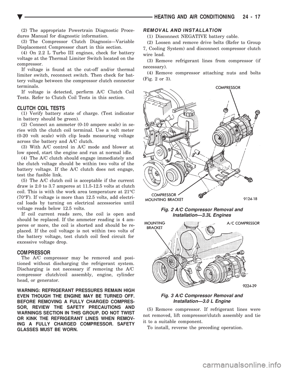
(Fig. 2 or 3).
(5) Remove compressor. If refrigerant lines were
not removed, lift compressor/clutch assembly and tie
it to a suitable component. To install, reverse the preceding operation.
Fig. 2 A/C Compressor Removal and InstallationÐ3.3L Engines
Fig. 3 A/C Compressor Removal and InstallationÐ3.0 L Engine
Ä HEATING AND AIR CONDITIONING 24 - 17
Page 2328 of 2438
FIXED DISPLACEMENT COMPRESSORÐMODEL 10PA17 INDEX
page page
Compressor ............................. 24
Compressor Clutch/Coil Assembly ............ 24
Compressor Front Shaft Seal ............... 27 Compressor High-Pressure Relief Valve
....... 30
Refrigerant System Diagnosis ............... 30
COMPRESSOR
COMPRESSOR NOISE
Excessive noise that occurs when the air condition-
ing is being used, can be caused by:
² Loose bolts
² Mounting brackets
² Loose clutch
² Excessive high refrigerant system operating pres-
sure Verify compressor drive belt condition, proper re-
frigerant charge and head pressure before compressor
repair is performed. For noise diagnostic procedures, refer to the Com-
pressor Noise and Compressor Clutch Diagnosis
chart in this section.
REMOVAL AND INSTALLATION
The A/C compressor may be removed and posi-
tioned without discharging the refrigerant system.
Discharging is not necessary if removing the A/C
compressor clutch/coil assembly, engine, cylinder
head, or generator.
WARNING: REFRIGERANT PRESSURES REMAIN
HIGH EVEN THOUGH THE ENGINE MAY BE
TURNED OFF. BEFORE REMOVING A FULLY
CHARGED COMPRESSOR, REVIEW THE SAFETY
PRECAUTIONS AND WARNINGS SECTION IN THIS
GROUP. DO NOT TWIST OR KINK THE REFRIGER-
ANT LINES WHEN REMOVING A FULLY CHARGED
COMPRESSOR. SAFETY GLASSES MUST BE
WORN.
(1) Disconnect Negative battery cable.
(2) Loosen and remove drive belts (refer to Group
7, Cooling System) and disconnect compressor clutch
wire lead. (3) Remove refrigerant lines from compressor (if
necessary). (4) Remove compressor attaching nuts and bolts.
(5) Remove compressor. If refrigerant lines were
not removed, lift compressor/clutch assembly and tie
it to a suitable component. To install, reverse the preceding operation. If nec-
essary, refer to Charging Refrigerant System in the
Refrigerant Service Procedures section.
COMPRESSOR CLUTCH/COIL ASSEMBLY
CLUTCH INOPERATIVE
The air conditioning compressor clutch electrical
circuit is controlled by the engine controller. The
controller is located in the engine compartment out-
board of the battery. If the compressor clutch does not engage:
Verify refrigerant charge.
If the compressor clutch still does not engage check
for battery voltage at the low pressure or differential
pressure cut-off switch located on the expansion
valve. If voltage is not detected, refer to:
² Group 8W, Wiring Diagrams.
² The appropriate Powertrain Diagnostic Procedures
Manual for diagnostic information. If voltage is detected at the cut-off switch, recon-
nect switch. Then check for battery voltage between
the compressor clutch connector terminals. If voltage is detected, perform A/C Clutch Coil
Tests.
CLUTCH COIL TESTS
(1) Verify battery state of charge. (Test indicator
in battery should be green). (2) Connect an ammeter (0-10 ampere scale) in se-
ries with the clutch coil terminal. Use a volt meter
(0-20 volt scale) with clip leads measuring voltage
across the battery and A/C clutch. (3) With A/C control in A/C mode and blower at
low speed, start the engine and run at normal idle. (4) The A/C clutch should engage immediately and
the clutch voltage should be within two volts of the
battery voltage. If the A/C clutch does not engage,
test the fusible link. (5) The A/C clutch coil is acceptable if the current
draw is 2.0 to 3.7 amperes at 11.5-12.5 volts at clutch
coil. This is with the work area temperature at 21ÉC
(70ÉF). If voltage is more than 12.5 volts, add electri-
cal loads by turning on electrical accessories until
voltage reads below 12.5 volts. If coil current reads zero, the coil is open and
should be replaced. If the ammeter reading is 4 am-
peres or more, the coil is shorted and should be re-
placed. If the coil voltage is not within two volts of
the battery voltage, test clutch coil feed circuit for
excessive voltage drop.
24 - 24 HEATING AND AIR CONDITIONING Ä
Page 2342 of 2438
FIXED DISPLACEMENT COMPRESSORÐMODEL SD709P INDEX
page page
Compressor ............................. 38
Compressor Clutch/Coil Assembly ............ 38
Compressor Shaft Seal .................... 41 Cylinder Head/Valve Plate
.................. 44
Description ............................. 38
Refrigerant System Diagnosis ............... 45
DESCRIPTION
The Sanden compressor is a 7 piston design. Sys-
tem lubrication is provided by 135 ml 615 ml (4.6 oz.
6 0.5 oz.) of 500 viscosity refrigerant oil.
The clutch used on the compressor consists of 3 ba-
sic components:
² The pulley
² Front plate
² Field coil
The pulley and field coil are attached to the front
head of the compressor with tapered snap rings. The
hub is keyed to the compressor shaft and is retained
on the shaft with a self-locking nut. Special service
tools are required to remove and install the clutch
plate on the compressor shaft.
COMPRESSOR
The A/C compressor may be removed and posi-
tioned without discharging the refrigerant system.
Discharging is not necessary if removing the A/C
compressor clutch/coil assembly, engine, cylinder
head, or generator.
WARNING: REFRIGERANT PRESSURES REMAIN
HIGH EVEN THOUGH THE ENGINE MAY BE
TURNED OFF. BEFORE REMOVING A FULLY
CHARGED COMPRESSOR, REVIEW THE SAFETY
PRECAUTIONS AND WARNINGS SECTION IN THIS
GROUP. DO NOT TWIST OR KINK THE REFRIGER-
ANT LINES WHEN REMOVING A FULLY CHARGED
COMPRESSOR. SAFETY GLASSES MUST BE
WORN.
REMOVAL
(1) Disconnect negative cable from battery.
(2) Loosen and remove drive belts (refer to group
7, Cooling System) and disconnect compressor clutch
wire lead. (3) Remove refrigerant lines from compressor (if
necessary). (4) Remove compressor attaching nuts and bolts.
(5) Remove compressor. If refrigerant lines were
not removed, lift compressor/clutch assembly and tie
it to a suitable component. To install, reverse the removal procedure.
COMPRESSOR CLUTCH/COIL ASSEMBLY
The magnetic clutch consists of a stationary elec-
tro-magnetic coil and a rotating pulley and plate as-
sembly. The electromagnetic coil is retained on the com-
pressor with a snap ring and is dimpled to maintain
its position. The pulley and plate assembly are mounted on the
compressor shaft. When the compressor is not in operation, the pul-
ley free wheels on the clutch hub bearing. When the
coil is energized the plate is magnetically engaged
with the pulley and turns the compressor shaft.
REMOVAL
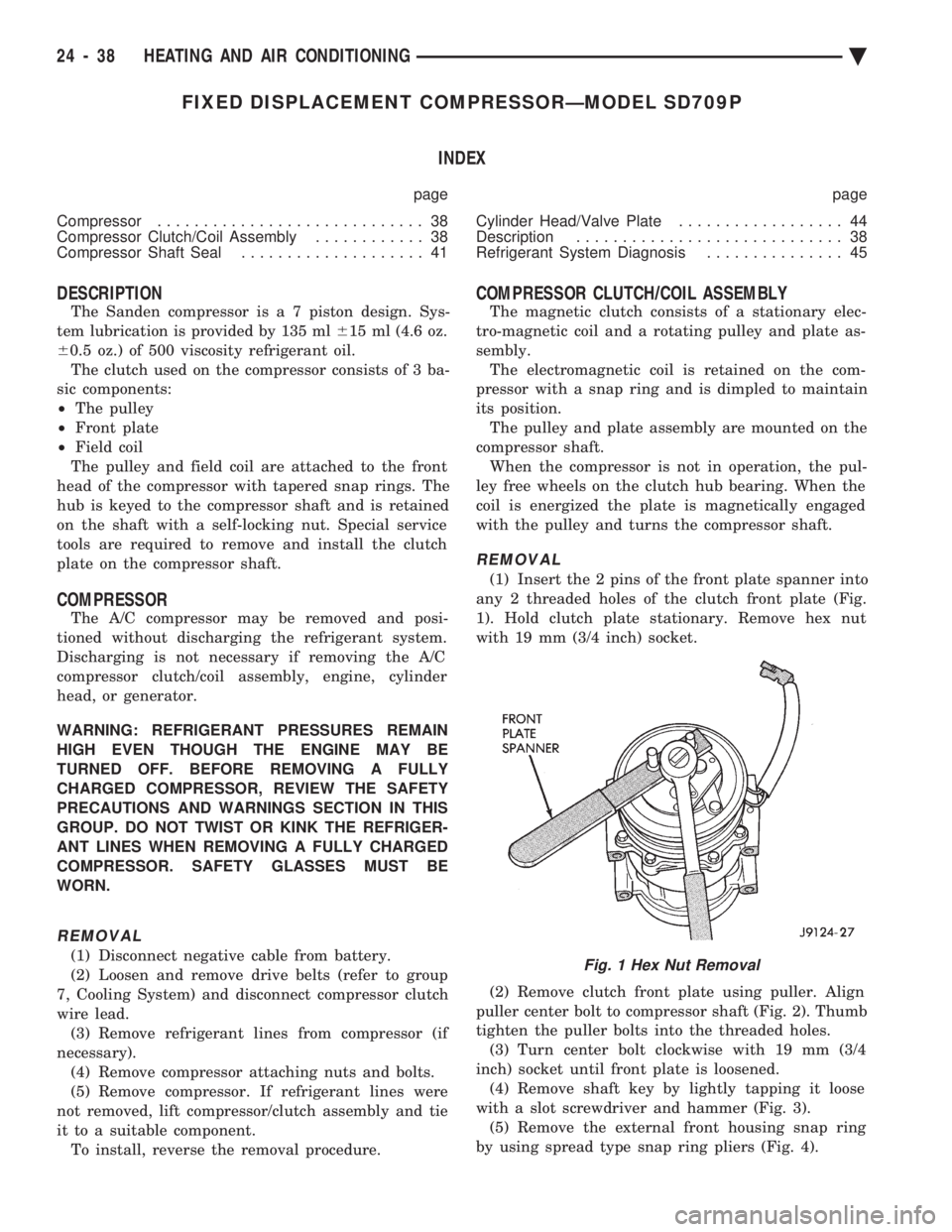
(1) Insert the 2 pins of the front plate spanner into
any 2 threaded holes of the clutch front plate (Fig.
1). Hold clutch plate stationary. Remove hex nut
with 19 mm (3/4 inch) socket.
(2) Remove clutch front plate using puller. Align
puller center bolt to compressor shaft (Fig. 2). Thumb
tighten the puller bolts into the threaded holes. (3) Turn center bolt clockwise with 19 mm (3/4
inch) socket until front plate is loosened. (4) Remove shaft key by lightly tapping it loose
with a slot screwdriver and hammer (Fig. 3). (5) Remove the external front housing snap ring
by using spread type snap ring pliers (Fig. 4).
Fig. 1 Hex Nut Removal
24 - 38 HEATING AND AIR CONDITIONING Ä
Page 2359 of 2438
(1) Disconnect the boot like wire connector at the
cut-off switch. (2) Using a sender unit type socket, remove the
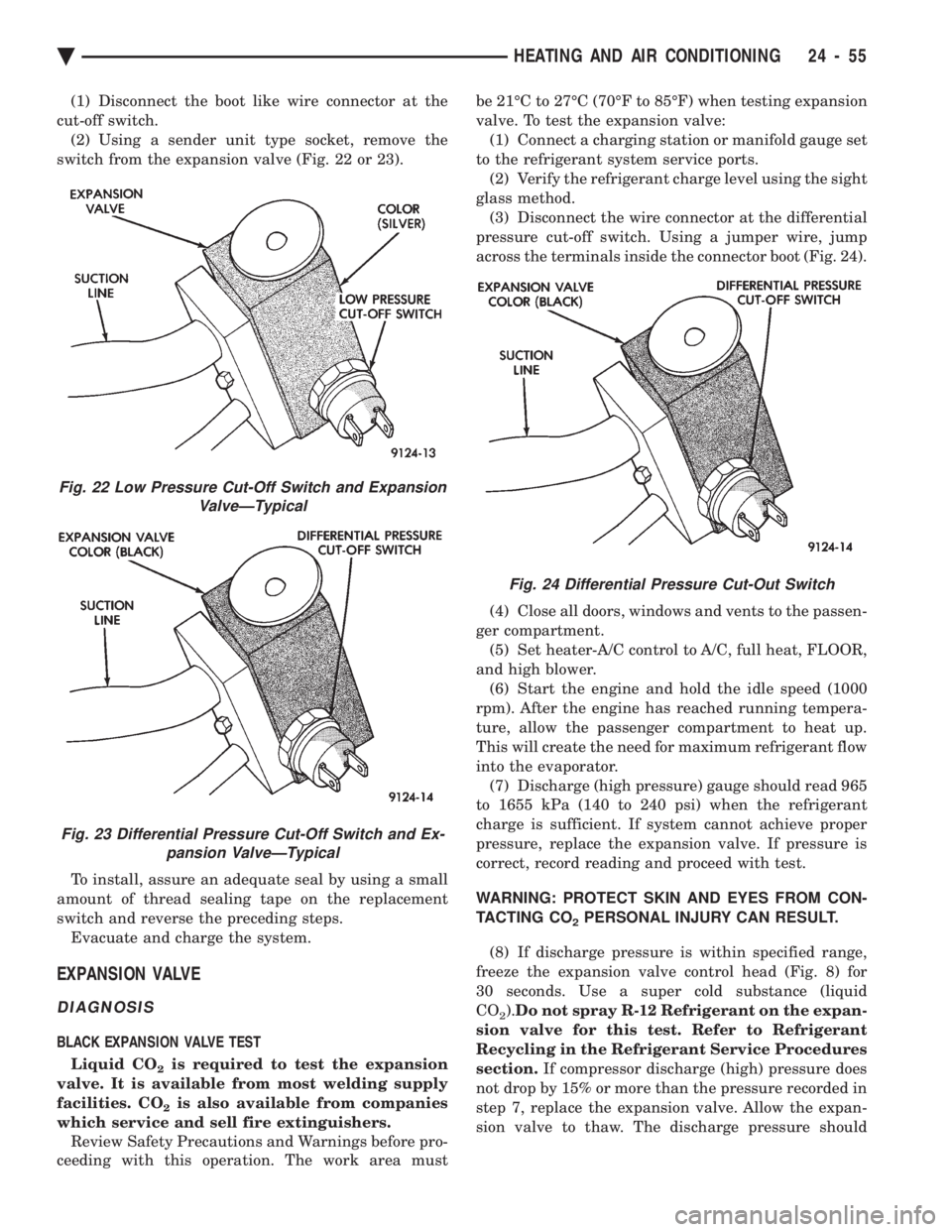
switch from the expansion valve (Fig. 22 or 23).
To install, assure an adequate seal by using a small
amount of thread sealing tape on the replacement
switch and reverse the preceding steps. Evacuate and charge the system.
EXPANSION VALVE
DIAGNOSIS
BLACK EXPANSION VALVE TEST
Liquid CO
2is required to test the expansion
valve. It is available from most welding supply
facilities. CO
2is also available from companies
which service and sell fire extinguishers. Review Safety Precautions and Warnings before pro-
ceeding with this operation. The work area must be 21ÉC to 27ÉC (70ÉF to 85ÉF) when testing expansion
valve. To test the expansion valve: (1) Connect a charging station or manifold gauge set
to the refrigerant system service ports. (2) Verify the refrigerant charge level using the sight
glass method. (3) Disconnect the wire connector at the differential
pressure cut-off switch. Using a jumper wire, jump
across the terminals inside the connector boot (Fig. 24).
(4) Close all doors, windows and vents to the passen-
ger compartment. (5) Set heater-A/C control to A/C, full heat, FLOOR,
and high blower. (6) Start the engine and hold the idle speed (1000
rpm). After the engine has reached running tempera-
ture, allow the passenger compartment to heat up.
This will create the need for maximum refrigerant flow
into the evaporator. (7) Discharge (high pressure) gauge should read 965
to 1655 kPa (140 to 240 psi) when the refrigerant
charge is sufficient. If system cannot achieve proper
pressure, replace the expansion valve. If pressure is
correct, record reading and proceed with test.
WARNING: PROTECT SKIN AND EYES FROM CON-
TACTING CO
2PERSONAL INJURY CAN RESULT.
(8) If discharge pressure is within specified range,
freeze the expansion valve control head (Fig. 8) for
30 seconds. Use a super cold substance (liquid
CO
2). Do not spray R-12 Refrigerant on the expan-
sion valve for this test. Refer to Refrigerant
Recycling in the Refrigerant Service Procedures
section. If compressor discharge (high) pressure does
not drop by 15% or more than the pressure recorded in
step 7, replace the expansion valve. Allow the expan-
sion valve to thaw. The discharge pressure should
Fig. 22 Low Pressure Cut-Off Switch and Expansion ValveÐTypical
Fig. 23 Differential Pressure Cut-Off Switch and Ex-pansion ValveÐTypical
Fig. 24 Differential Pressure Cut-Out Switch
Ä HEATING AND AIR CONDITIONING 24 - 55
Page 2360 of 2438
stabilize to the pressure recorded in step 7. If the
pressure does not stabilize, replace the expansion
valve.When expansion valve tests are complete, refer to
Heater and A/C Performance Tests and remove all test
equipment before returning vehicle to use.
SILVER EXPANSION VALVE TEST
Expansion valve tests should be performed af-
ter compressor tests. Liquid CO
2is required to test the expansion
valve. It is available from most welding supply
facilities. CO
2is also available from companies
which service and sell fire extinguishers. Review Safety Precautions and Warnings in the
General Information section of this Group. The work
area and vehicle must be 21ÉC to 27ÉC (70ÉF to 85ÉF)
when testing expansion valve. To test the expansion
valve: (1) Connect a charging station or manifold gauge set
to the refrigerant system service ports. (2) Verify the refrigerant charge level using the sight
glass method. (3) Disconnect wire connector at low pressure cut-off
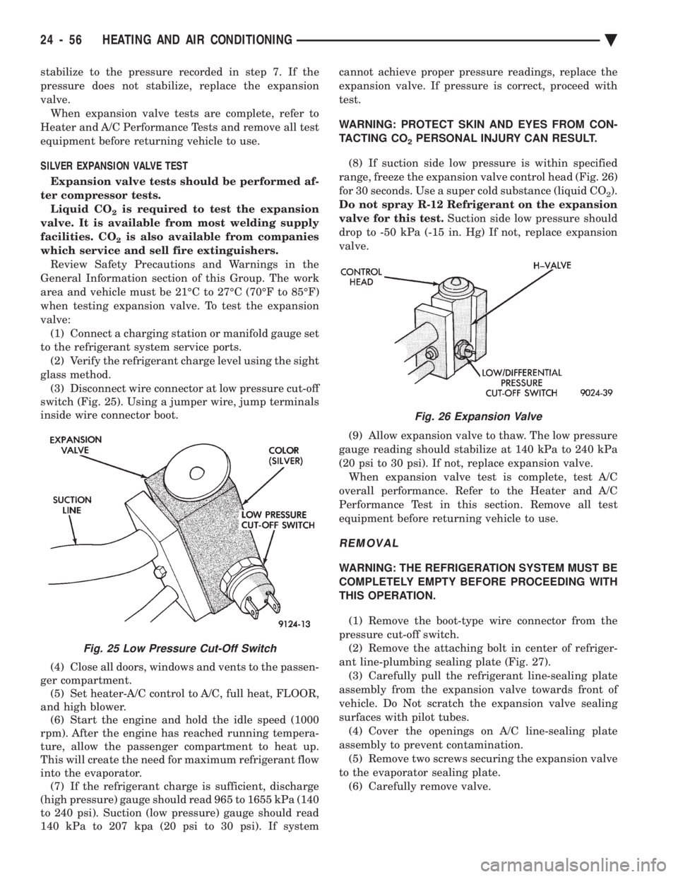
switch (Fig. 25). Using a jumper wire, jump terminals
inside wire connector boot.
(4) Close all doors, windows and vents to the passen-
ger compartment. (5) Set heater-A/C control to A/C, full heat, FLOOR,
and high blower. (6) Start the engine and hold the idle speed (1000
rpm). After the engine has reached running tempera-
ture, allow the passenger compartment to heat up.
This will create the need for maximum refrigerant flow
into the evaporator. (7) If the refrigerant charge is sufficient, discharge
(high pressure) gauge should read 965 to 1655 kPa (140
to 240 psi). Suction (low pressure) gauge should read
140 kPa to 207 kpa (20 psi to 30 psi). If system cannot achieve proper pressure readings, replace the
expansion valve. If pressure is correct, proceed with
test.
WARNING: PROTECT SKIN AND EYES FROM CON-
TACTING CO
2PERSONAL INJURY CAN RESULT.
(8) If suction side low pressure is within specified
range, freeze the expansion valve control head (Fig. 26)
for 30 seconds. Use a super cold substance (liquid CO
2).
Do not spray R-12 Refrigerant on the expansion
valve for this test. Suction side low pressure should
drop to -50 kPa (-15 in. Hg) If not, replace expansion
valve.
(9) Allow expansion valve to thaw. The low pressure
gauge reading should stabilize at 140 kPa to 240 kPa
(20 psi to 30 psi). If not, replace expansion valve. When expansion valve test is complete, test A/C
overall performance. Refer to the Heater and A/C
Performance Test in this section. Remove all test
equipment before returning vehicle to use.
REMOVAL
WARNING: THE REFRIGERATION SYSTEM MUST BE
COMPLETELY EMPTY BEFORE PROCEEDING WITH
THIS OPERATION.
(1) Remove the boot-type wire connector from the
pressure cut-off switch. (2) Remove the attaching bolt in center of refriger-
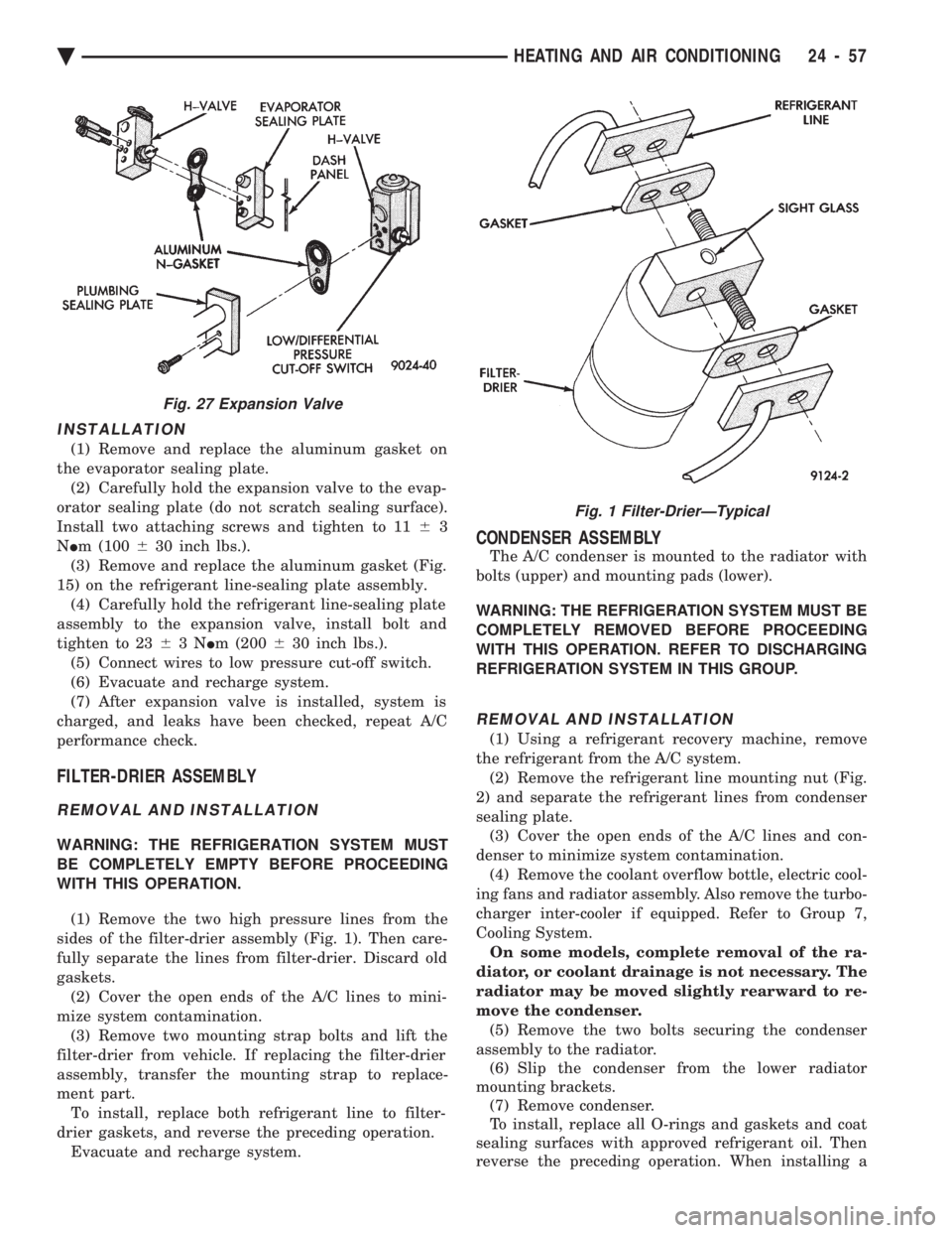
ant line-plumbing sealing plate (Fig. 27). (3) Carefully pull the refrigerant line-sealing plate
assembly from the expansion valve towards front of
vehicle. Do Not scratch the expansion valve sealing
surfaces with pilot tubes. (4) Cover the openings on A/C line-sealing plate
assembly to prevent contamination. (5) Remove two screws securing the expansion valve
to the evaporator sealing plate. (6) Carefully remove valve.
Fig. 25 Low Pressure Cut-Off Switch
Fig. 26 Expansion Valve
24 - 56 HEATING AND AIR CONDITIONING Ä
Page 2361 of 2438
INSTALLATION
(1) Remove and replace the aluminum gasket on
the evaporator sealing plate. (2) Carefully hold the expansion valve to the evap-
orator sealing plate (do not scratch sealing surface).
Install two attaching screws and tighten to 11 63
N Im (100 630 inch lbs.).
(3) Remove and replace the aluminum gasket (Fig.
15) on the refrigerant line-sealing plate assembly. (4) Carefully hold the refrigerant line-sealing plate
assembly to the expansion valve, install bolt and
tighten to 23 63N Im (200 630 inch lbs.).
(5) Connect wires to low pressure cut-off switch.
(6) Evacuate and recharge system.
(7) After expansion valve is installed, system is
charged, and leaks have been checked, repeat A/C
performance check.
FILTER-DRIER ASSEMBLY
REMOVAL AND INSTALLATION
WARNING: THE REFRIGERATION SYSTEM MUST
BE COMPLETELY EMPTY BEFORE PROCEEDING
WITH THIS OPERATION.
(1) Remove the two high pressure lines from the
sides of the filter-drier assembly (Fig. 1). Then care-
fully separate the lines from filter-drier. Discard old
gaskets. (2) Cover the open ends of the A/C lines to mini-
mize system contamination. (3) Remove two mounting strap bolts and lift the
filter-drier from vehicle. If replacing the filter-drier
assembly, transfer the mounting strap to replace-
ment part. To install, replace both refrigerant line to filter-
drier gaskets, and reverse the preceding operation. Evacuate and recharge system.
CONDENSER ASSEMBLY
The A/C condenser is mounted to the radiator with
bolts (upper) and mounting pads (lower).
WARNING: THE REFRIGERATION SYSTEM MUST BE
COMPLETELY REMOVED BEFORE PROCEEDING
WITH THIS OPERATION. REFER TO DISCHARGING
REFRIGERATION SYSTEM IN THIS GROUP.
REMOVAL AND INSTALLATION
(1) Using a refrigerant recovery machine, remove
the refrigerant from the A/C system. (2) Remove the refrigerant line mounting nut (Fig.
2) and separate the refrigerant lines from condenser
sealing plate. (3) Cover the open ends of the A/C lines and con-
denser to minimize system contamination. (4) Remove the coolant overflow bottle, electric cool-
ing fans and radiator assembly. Also remove the turbo-
charger inter-cooler if equipped. Refer to Group 7,
Cooling System. On some models, complete removal of the ra-
diator, or coolant drainage is not necessary. The
radiator may be moved slightly rearward to re-
move the condenser. (5) Remove the two bolts securing the condenser
assembly to the radiator. (6) Slip the condenser from the lower radiator
mounting brackets. (7) Remove condenser.
To install, replace all O-rings and gaskets and coat
sealing surfaces with approved refrigerant oil. Then
reverse the preceding operation. When installing a
Fig. 27 Expansion Valve
Fig. 1 Filter-DrierÐTypical
Ä HEATING AND AIR CONDITIONING 24 - 57