charging CHEVROLET DYNASTY 1993 Manual PDF
[x] Cancel search | Manufacturer: CHEVROLET, Model Year: 1993, Model line: DYNASTY, Model: CHEVROLET DYNASTY 1993Pages: 2438, PDF Size: 74.98 MB
Page 1886 of 2438
The PCM regulates ignition timing, air-fuel ratio,
emission control devices, cooling fan, charging sys-
tem, idle speed and speed control. Various sensors
provide the inputs necessary for the PCM to correctly
operate these systems. In addition to the sensors,
various switches also provide inputs to the PCM. All inputs to the PCM are converted into signals.
The PCM can adapt its programming to meet chang-
ing operating conditions. Fuel is injected into the intake port above the in-
take valve in precise metered amounts through elec-
trically operated injectors. The PCM fires the
injectors in a specific sequence. The PCM maintains
an air fuel ratio of 14.7 parts air to 1 part fuel by
constantly adjusting injector pulse width. Injector
pulse width is the length of time the injector is ener-
gized. The PCM adjusts injector pulse width by opening
and closing the ground path to the injector. Engine
RPM (speed) and manifold absolute pressure (air
density) are the primary inputs that determine injec-
tor pulse width.
SYSTEM DIAGNOSIS
The PCM tests many of its own input and output
circuits. If a fault is found in a major system, the in-
formation is stored in memory. Technicians can dis-
play fault information through the malfunction
indicator lamp (instrument panel Check Engine
lamp) or by connecting the DRBII scan tool. For di-
agnostic trouble code information, refer to the 3.3L/
3.8L Multi-Point Fuel InjectionÐOn-Board
Diagnostics section of this group.
CCD BUS
Various modules exchange information through a
communications port called the CCD Bus. The pow-
ertrain control module (PCM) transmits engine RPM
and vehicle load information on the CCD Bus.
POWERTRAIN CONTROL MODULE
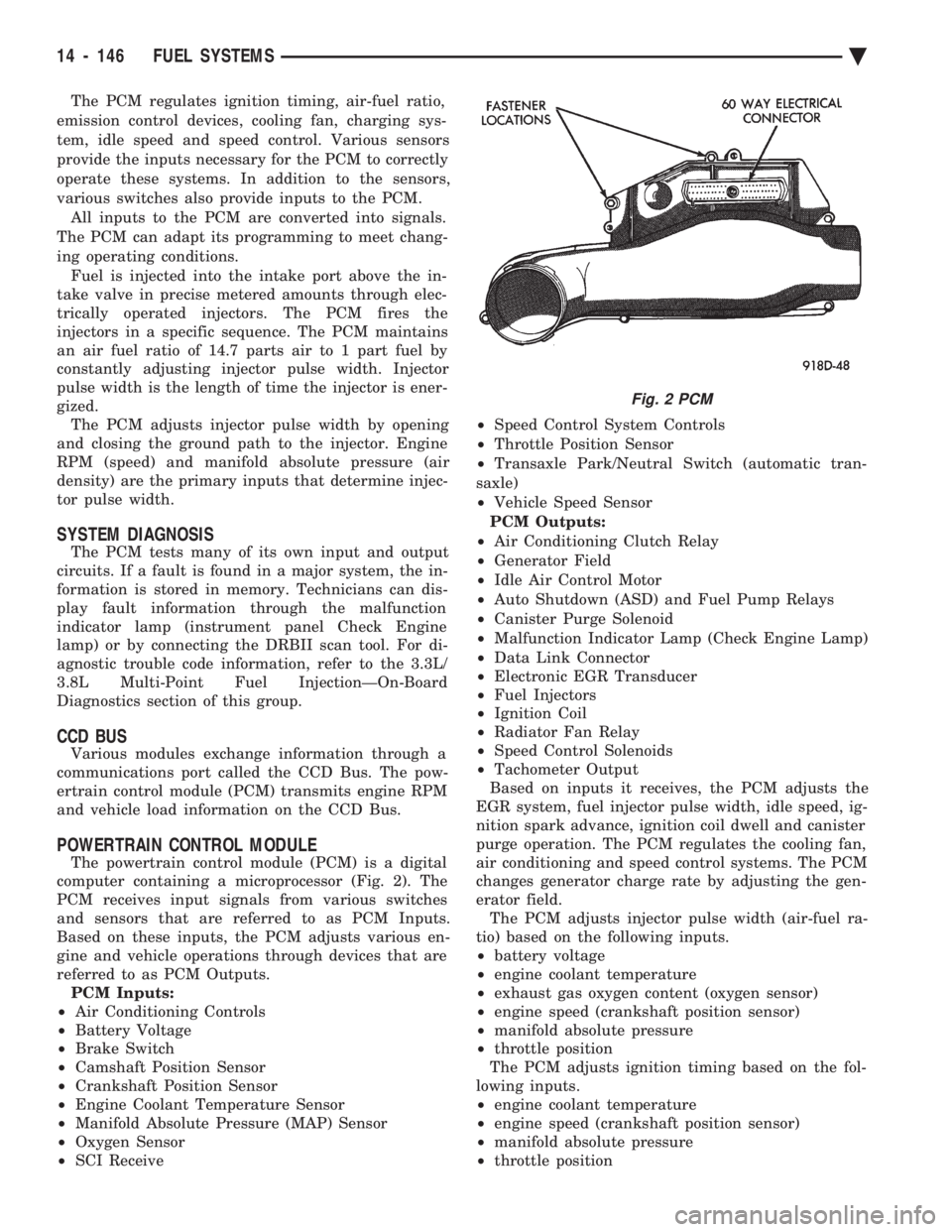
The powertrain control module (PCM) is a digital
computer containing a microprocessor (Fig. 2). The
PCM receives input signals from various switches
and sensors that are referred to as PCM Inputs.
Based on these inputs, the PCM adjusts various en-
gine and vehicle operations through devices that are
referred to as PCM Outputs. PCM Inputs:
² Air Conditioning Controls
² Battery Voltage
² Brake Switch
² Camshaft Position Sensor
² Crankshaft Position Sensor
² Engine Coolant Temperature Sensor
² Manifold Absolute Pressure (MAP) Sensor
² Oxygen Sensor
² SCI Receive ²
Speed Control System Controls
² Throttle Position Sensor
² Transaxle Park/Neutral Switch (automatic tran-
saxle)
² Vehicle Speed Sensor
PCM Outputs:
² Air Conditioning Clutch Relay
² Generator Field
² Idle Air Control Motor
² Auto Shutdown (ASD) and Fuel Pump Relays
² Canister Purge Solenoid
² Malfunction Indicator Lamp (Check Engine Lamp)
² Data Link Connector
² Electronic EGR Transducer
² Fuel Injectors
² Ignition Coil
² Radiator Fan Relay
² Speed Control Solenoids
² Tachometer Output
Based on inputs it receives, the PCM adjusts the
EGR system, fuel injector pulse width, idle speed, ig-
nition spark advance, ignition coil dwell and canister
purge operation. The PCM regulates the cooling fan,
air conditioning and speed control systems. The PCM
changes generator charge rate by adjusting the gen-
erator field. The PCM adjusts injector pulse width (air-fuel ra-
tio) based on the following inputs.
² battery voltage
² engine coolant temperature
² exhaust gas oxygen content (oxygen sensor)
² engine speed (crankshaft position sensor)
² manifold absolute pressure
² throttle position
The PCM adjusts ignition timing based on the fol-
lowing inputs.
² engine coolant temperature
² engine speed (crankshaft position sensor)
² manifold absolute pressure
² throttle position
Fig. 2 PCM
14 - 146 FUEL SYSTEMS Ä
Page 1890 of 2438
SPEED CONTROLÐPCM INPUT
The speed control system provides four separate
voltages (inputs) to the PCM. The voltages corre-
spond to the On/Off, Set, and Resume. The speed control ON voltage informs the PCM
that the speed control system has been activated.
The speed control SET voltage informs the PCM that
a fixed vehicle speed has been selected. The speed
control RESUME voltage indicates the previous fixed
speed is requested. The speed control OFF voltage
tells the PCM that the speed control system has been
deactivated. Refer to Group 8H for further speed con-
trol information.
TRANSAXLE PARK/NEUTRAL SWITCHÐPCM
INPUT
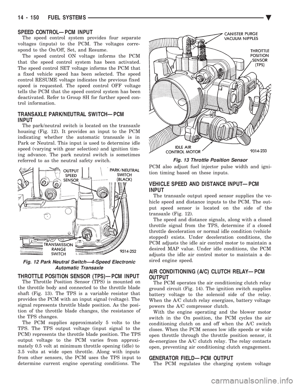
The park/neutral switch is located on the transaxle
housing (Fig. 12). It provides an input to the PCM
indicating whether the automatic transaxle is in
Park or Neutral. This input is used to determine idle
speed (varying with gear selection) and ignition tim-
ing advance. The park neutral switch is sometimes
referred to as the neutral safety switch.
THROTTLE POSITION SENSOR (TPS)ÐPCM INPUT
The Throttle Position Sensor (TPS) is mounted on
the throttle body and connected to the throttle blade
shaft (Fig. 13). The TPS is a variable resistor that
provides the PCM with an input signal (voltage). The
signal represents throttle blade position. As the posi-
tion of the throttle blade changes, the resistance of
the TPS changes. The PCM supplies approximately 5 volts to the
TPS. The TPS output voltage (input signal to the
PCM) represents the throttle blade position. The TPS
output voltage to the PCM varies from approxi-
mately 0.5 volt at minimum throttle opening (idle) to
3.5 volts at wide open throttle. Along with inputs
from other sensors, the PCM uses the TPS input to
determine current engine operating conditions. The PCM also adjust fuel injector pulse width and igni-
tion timing based on these inputs.
VEHICLE SPEED AND DISTANCE INPUTÐPCM
INPUT
The transaxle output speed sensor supplies the ve-
hicle speed and distance inputs to the PCM. The out-
put speed sensor is located on the side of the
transaxle (Fig. 12). The speed and distance signals, along with a closed
throttle signal from the TPS, determine if a closed
throttle deceleration or normal idle condition (vehicle
stopped) exists. Under deceleration conditions, the
PCM adjusts the idle air control motor to maintain a
desired MAP value. Under idle conditions, the PCM
adjusts the idle air control motor to maintain a de-
sired engine speed.
AIR CONDITIONING (A/C) CLUTCH RELAYÐPCM
OUTPUT
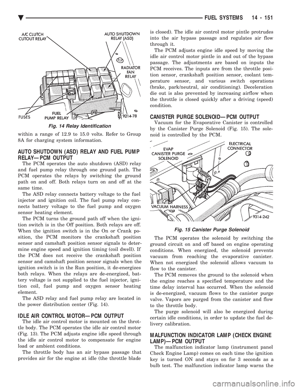
The PCM operates the air conditioning clutch relay
ground circuit (Fig. 14). The ignition switch supplies
battery voltage to the solenoid side of the relay.
When the A/C clutch relay energizes, battery voltage
powers the A/C compressor clutch. With the engine operating and the blower motor
switch in the On position, the PCM cycles the air
conditioning clutch on and off when the A/C switch
closes. When the PCM senses low idle speeds or wide
open throttle through the throttle position sensor, it
de-energizes the A/C clutch relay. The relay contacts
open, preventing air conditioning clutch engagement.
GENERATOR FIELDÐPCM OUTPUT
The PCM regulates the charging system voltage
Fig. 13 Throttle Position Sensor
Fig. 12 Park Neutral SwitchÐ4-Speed Electronic Automatic Transaxle
14 - 150 FUEL SYSTEMS Ä
Page 1891 of 2438
within a range of 12.9 to 15.0 volts. Refer to Group
8A for charging system information.
AUTO SHUTDOWN (ASD) RELAY AND FUEL PUMP
RELAYÐPCM OUTPUT
The PCM operates the auto shutdown (ASD) relay
and fuel pump relay through one ground path. The
PCM operates the relays by switching the ground
path on and off. Both relays turn on and off at the
same time. The ASD relay connects battery voltage to the fuel
injector and ignition coil. The fuel pump relay con-
nects battery voltage to the fuel pump and oxygen
sensor heating element. The PCM turns the ground path off when the igni-
tion switch is in the Off position. Both relays are off.
When the ignition switch is in the On or Crank po-
sition, the PCM monitors the crankshaft position
sensor and camshaft position sensor signals to deter-
mine engine speed and ignition timing (coil dwell). If
the PCM does not receive the crankshaft position
sensor and camshaft position sensor signals when the
ignition switch is in the Run position, it de-energizes
both relays. When the relays are de-energized, bat-
tery voltage is not supplied to the fuel injector, igni-
tion coil, fuel pump and oxygen sensor heating
element. The ASD relay and fuel pump relay are located in
the power distribution center (Fig. 14).
IDLE AIR CONTROL MOTORÐPCM OUTPUT
The idle air control motor is mounted on the throt-
tle body. The PCM operates the idle air control motor
(Fig. 13). The PCM adjusts engine idle speed through
the idle air control motor to compensate for engine
load or ambient conditions. The throttle body has an air bypass passage that
provides air for the engine at idle (the throttle blade is closed). The idle air control motor pintle protrudes
into the air bypass passage and regulates air flow
through it. The PCM adjusts engine idle speed by moving the
idle air control motor pintle in and out of the bypass
passage. The adjustments are based on inputs the
PCM receives. The inputs are from the throttle posi-
tion sensor, crankshaft position sensor, coolant tem-
perature sensor, and various switch operations
(brake, park/neutral, air conditioning). Deceleration
die out is also prevented by increasing airflow when
the throttle is closed quickly after a driving (speed)
condition.
CANISTER PURGE SOLENOIDÐPCM OUTPUT
Vacuum for the Evaporative Canister is controlled
by the Canister Purge Solenoid (Fig. 15). The sole-
noid is controlled by the PCM.
The PCM operates the solenoid by switching the
ground circuit on and off based on engine operating
conditions. When energized, the solenoid prevents
vacuum from reaching the evaporative canister.
When not energized the solenoid allows vacuum to
flow to the canister. The PCM removes the ground to the solenoid when
the engine reaches a specified temperature and the
time delay interval has occurred. When the solenoid
is de-energized, vacuum flows to the canister purge
valve. Vapors are purged from the canister and flow
to the throttle body. The purge solenoid will also be energized during
certain idle conditions, in order to update the fuel de-
livery calibration.
MALFUNCTION INDICATOR LAMP (CHECK ENGINE
LAMP)ÐPCM OUTPUT
The malfunction indicator lamp (instrument panel
Check Engine Lamp) comes on each time the ignition
key is turned ON and stays on for 3 seconds as a
bulb test. The malfunction indicator lamp warns the
Fig. 14 Relay Identification
Fig. 15 Canister Purge Solenoid
Ä FUEL SYSTEMS 14 - 151
Page 1892 of 2438
operator that the PCM has entered a Limp-in mode.
During Limp-in Mode, the PCM attempts to keep the
system operational. The malfunction indicator signals
the need for immediate service. In limp-in mode, the
PCM compensates for the failure of certain components
that send incorrect signals. The PCM substitutes for
the incorrect signals with inputs from other sensors. Signals that can trigger the Malfunction Indi-
cator lamp (Check Engine Lamp).
² Engine Coolant Temperature Sensor
² Manifold Absolute Pressure Sensor
² Throttle Position Sensor
² Battery Voltage Input
² An Emission Related System (California vehicles)
² Charging system
The malfunction indicator (Check Engine Lamp) can
also display diagnostic trouble codes. Cycle the ignition
switch on, off, on, off, on, within five seconds and any
diagnostic trouble codes stored in the PCM will be
displayed. Refer to the 3.3L and 3.8L Multi-Port Fuel
InjectionÐOn-Board Diagnostics section of this Group
for Diagnostic Trouble Code Descriptions.
DATA LINK CONNECTORÐPCM OUTPUT
The data link connector provides the technician with
the means to connect the DRBII scan tool to diagnosis
the vehicle.
TRANSAXLE CONTROL MODULEÐPCM OUTPUT
The PCM supplies the following information to the
electronic automatic transaxle control module through
the CCD Bus:
² battery temperature
² brake switch input
² engine coolant temperature
² manifold absolute pressure (MAP)
² speed control information
ELECTRIC EGR TRANSDUCER (EET)
SOLENOIDÐPCM OUTPUT
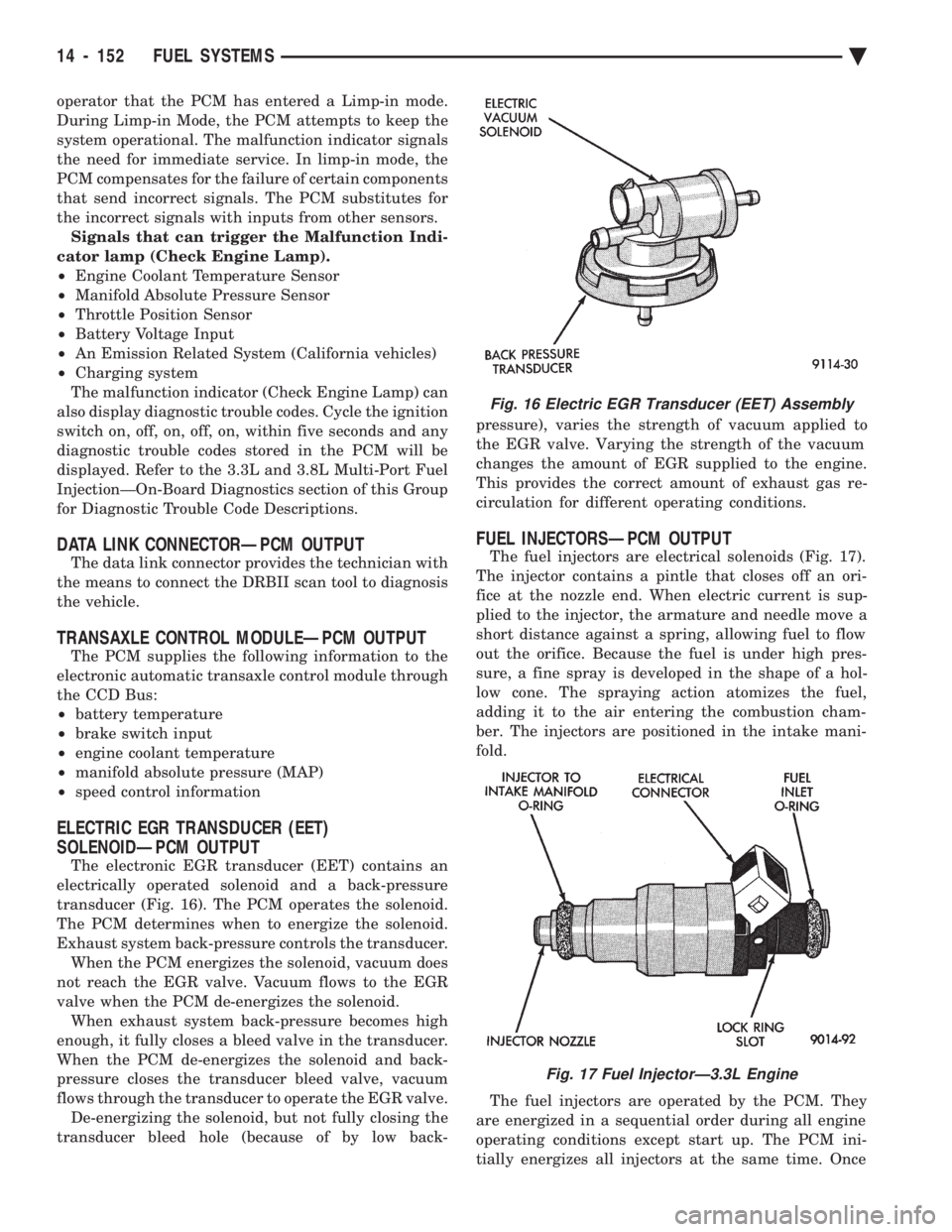
The electronic EGR transducer (EET) contains an
electrically operated solenoid and a back-pressure
transducer (Fig. 16). The PCM operates the solenoid.
The PCM determines when to energize the solenoid.
Exhaust system back-pressure controls the transducer. When the PCM energizes the solenoid, vacuum does
not reach the EGR valve. Vacuum flows to the EGR
valve when the PCM de-energizes the solenoid. When exhaust system back-pressure becomes high
enough, it fully closes a bleed valve in the transducer.
When the PCM de-energizes the solenoid and back-
pressure closes the transducer bleed valve, vacuum
flows through the transducer to operate the EGR valve. De-energizing the solenoid, but not fully closing the
transducer bleed hole (because of by low back- pressure), varies the strength of vacuum applied to
the EGR valve. Varying the strength of the vacuum
changes the amount of EGR supplied to the engine.
This provides the correct amount of exhaust gas re-
circulation for different operating conditions.
FUEL INJECTORSÐPCM OUTPUT
The fuel injectors are electrical solenoids (Fig. 17).
The injector contains a pintle that closes off an ori-
fice at the nozzle end. When electric current is sup-
plied to the injector, the armature and needle move a
short distance against a spring, allowing fuel to flow
out the orifice. Because the fuel is under high pres-
sure, a fine spray is developed in the shape of a hol-
low cone. The spraying action atomizes the fuel,
adding it to the air entering the combustion cham-
ber. The injectors are positioned in the intake mani-
fold.
The fuel injectors are operated by the PCM. They
are energized in a sequential order during all engine
operating conditions except start up. The PCM ini-
tially energizes all injectors at the same time. Once
Fig. 16 Electric EGR Transducer (EET) Assembly
Fig. 17 Fuel InjectorÐ3.3L Engine
14 - 152 FUEL SYSTEMS Ä
Page 1906 of 2438
S/C Vacuum Solenoid
A/C Clutch Relay
EGR Solenoid
Auto Shutdown Relay
Radiator Fan Relay
Purge Solenoid
Malfunction Indicator Lamp (Check Engine Lamp)
STATE DISPLAY SENSORS
Connect the DRBII scan tool to the vehicle and ac-
cess the State Display screen. Then access Sensor
Display. The following is a list of the engine control
system functions accessible through the Sensor Dis-
play screen. Oxygen Sensor Signal
Engine Coolant Temperature
Engine Coolant Temp Sensor
Throttle Position
Minimum Throttle
Battery Voltage
MAP Sensor Reading
Idle Air Control Motor Position
Adaptive Fuel Factor
Barometric Pressure
Min Airflow Idle Spd (speed)
Engine Speed
DIS Sensor Status
Fault #1 Key-On Info
Module Spark Advance
Speed Control Target
Fault #2 Key-on Info
Fault #3 Key-on Info
Speed Control Status
Speed Control Switch Voltage
Charging System Goal
Theft Alarm Status
Map Sensor Voltage
Vehicle Speed
Oxygen Sensor State
MAP Gauge Reading
Throttle Opening (percentage)
Total Spark Advance
CIRCUIT ACTUATION TEST MODE
The circuit actuation test mode checks for proper
operation of output circuits or devices which the pow-
ertrain control module (PCM) cannot internally rec-
ognize. The PCM can attempt to activate these
outputs and allow an observer to verify proper oper-
ation. Most of the tests provide an audible or visual
indication of device operation (click of relay contacts,
spray fuel, etc.). Except for intermittent conditions, if
a device functions properly during testing, assume
the device, its associated wiring, and driver circuit
working correctly.
OBTAINING CIRCUIT ACTUATION TEST
Connect the DRBII scan tool to the vehicle and ac-
cess the Actuators screen. The following is a list of
the engine control system functions accessible
through Actuators screens. Stop All Tests
Ignition Coil #1
Ignition Coil #2
Ignition Coil #3
Fuel Injector #1
Fuel Injector #2
Fuel Injector #3
Fuel Injector #4
Fuel Injector #5
Fuel Injector #6
Idle Air Control Motor Open/Close
Radiator Fan Relay
A/C Clutch Relay
Auto Shutdown Relay
EVAP Purge Solenoid
S/C Servo Solenoids
Generator Field
EGR Solenoid
All Solenoids/Relays
ASD Fuel System Test
Speed Control Vacuum Solenoid
Speed Control Vent Solenoid
THROTTLE BODY MINIMUM AIR FLOW CHECK
PROCEDURE
(1) Warm engine in Park or Neutral until the cool-
ing fan has cycled on and off at least once. (2) Ensure that all accessories are off.
(3) Shut off engine.
(4) Disconnect the PCV valve hose from the intake
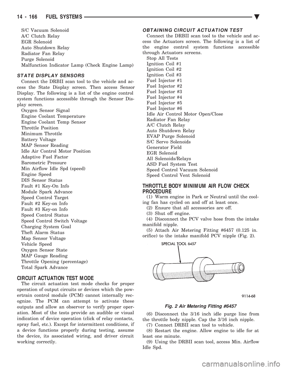
manifold nipple. (5) Attach Air Metering Fitting #6457 (0.125 in.
orifice) to the intake manifold PCV nipple (Fig. 2).
(6) Disconnect the 3/16 inch idle purge line from
the throttle body nipple. Cap the 3/16 inch nipple. (7) Connect DRBII scan tool to vehicle.
(8) Restart the engine. Allow engine to idle for at
least one minute. (9) Using the DRBII scan tool, access Min. Airflow
Idle Spd.
Fig. 2 Air Metering Fitting #6457
14 - 166 FUEL SYSTEMS Ä
Page 2312 of 2438
REFRIGERANT SERVICE PROCEDURES INDEX
page page
Adding Partial Refrigerant Charge ............ 10
Charging Refrigerant SystemÐEmpty System . . . 11
Discharging Refrigerant System .............. 11
Evacuating Refrigerant System .............. 11
Manifold Gauge Set Connections ............. 9 Oil Level
............................... 12
R-12 Refrigerant Equipment ................. 8
Refrigerant Recycling ...................... 9
Sight Glass Refrigerant Level Inspection ........ 8
Testing for Refrigerant Leaks ............... 10
SIGHT GLASS REFRIGERANT LEVEL INSPECTION
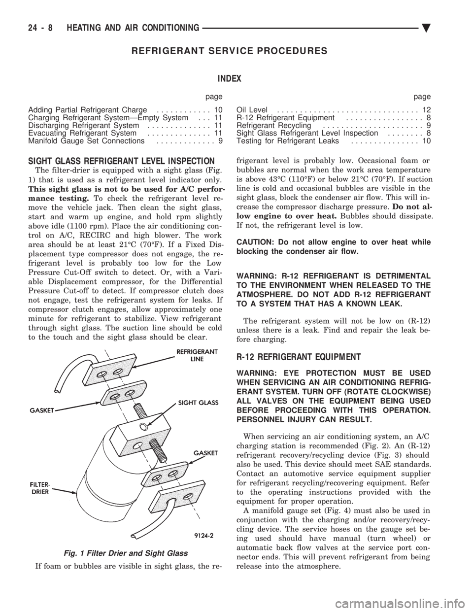
The filter-drier is equipped with a sight glass (Fig.
1) that is used as a refrigerant level indicator only.
This sight glass is not to be used for A/C perfor-
mance testing. To check the refrigerant level re-
move the vehicle jack. Then clean the sight glass,
start and warm up engine, and hold rpm slightly
above idle (1100 rpm). Place the air conditioning con-
trol on A/C, RECIRC and high blower. The work
area should be at least 21ÉC (70ÉF). If a Fixed Dis-
placement type compressor does not engage, the re-
frigerant level is probably too low for the Low
Pressure Cut-Off switch to detect. Or, with a Vari-
able Displacement compressor, for the Differential
Pressure Cut-off to detect. If compressor clutch does
not engage, test the refrigerant system for leaks. If
compressor clutch engages, allow approximately one
minute for refrigerant to stabilize. View refrigerant
through sight glass. The suction line should be cold
to the touch and the sight glass should be clear.
If foam or bubbles are visible in sight glass, the re- frigerant level is probably low. Occasional foam or
bubbles are normal when the work area temperature
is above 43ÉC (110ÉF) or below 21ÉC (70ÉF). If suction
line is cold and occasional bubbles are visible in the
sight glass, block the condenser air flow. This will in-
crease the compressor discharge pressure. Do not al-
low engine to over heat. Bubbles should dissipate.
If not, the refrigerant level is low.
CAUTION: Do not allow engine to over heat while
blocking the condenser air flow.
WARNING: R-12 REFRIGERANT IS DETRIMENTAL
TO THE ENVIRONMENT WHEN RELEASED TO THE
ATMOSPHERE. DO NOT ADD R-12 REFRIGERANT
TO A SYSTEM THAT HAS A KNOWN LEAK.
The refrigerant system will not be low on (R-12)
unless there is a leak. Find and repair the leak be-
fore charging.
R-12 REFRIGERANT EQUIPMENT
WARNING: EYE PROTECTION MUST BE USED
WHEN SERVICING AN AIR CONDITIONING REFRIG-
ERANT SYSTEM. TURN OFF (ROTATE CLOCKWISE)
ALL VALVES ON THE EQUIPMENT BEING USED
BEFORE PROCEEDING WITH THIS OPERATION.
PERSONNEL INJURY CAN RESULT.
When servicing an air conditioning system, an A/C
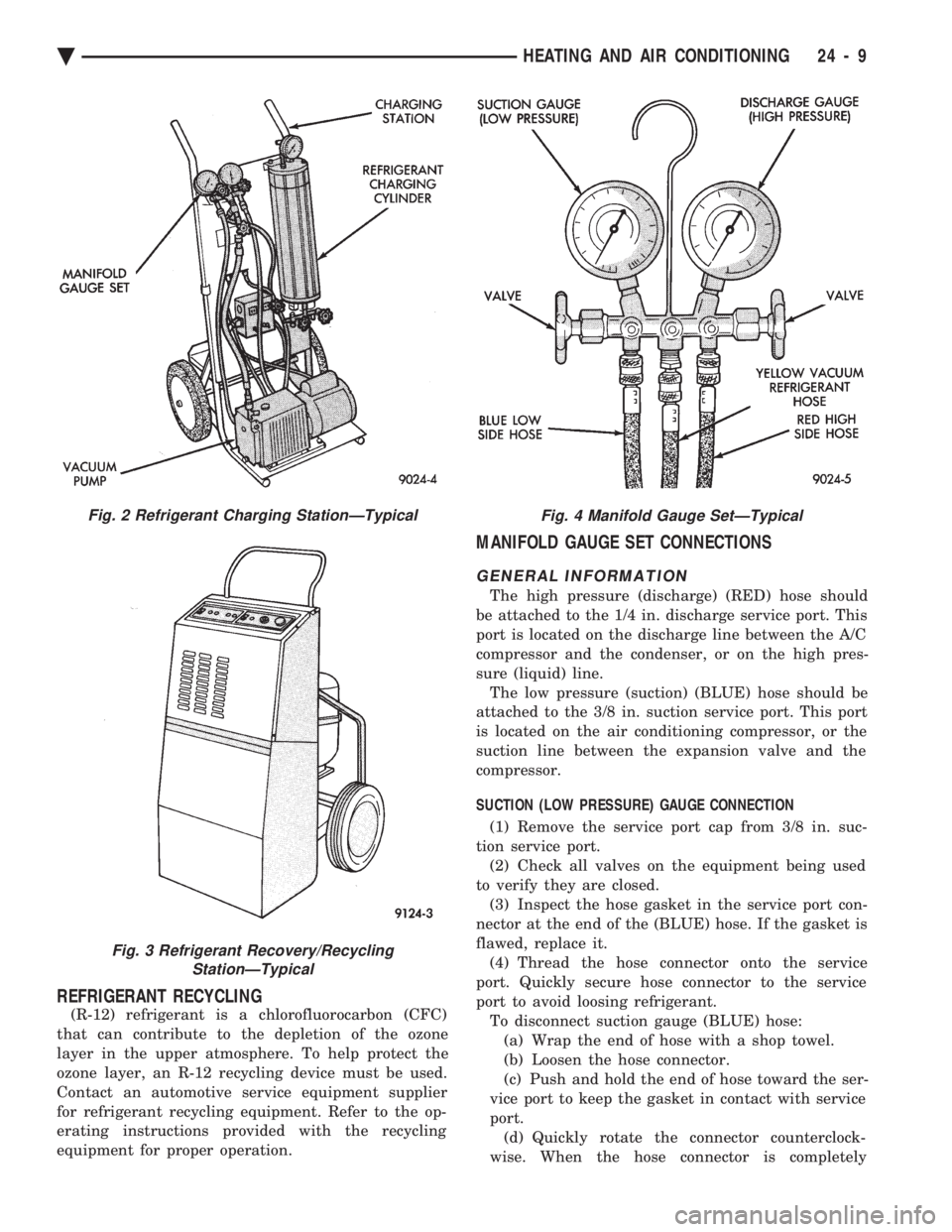
charging station is recommended (Fig. 2). An (R-12)
refrigerant recovery/recycling device (Fig. 3) should
also be used. This device should meet SAE standards.
Contact an automotive service equipment supplier
for refrigerant recycling/recovering equipment. Refer
to the operating instructions provided with the
equipment for proper operation. A manifold gauge set (Fig. 4) must also be used in
conjunction with the charging and/or recovery/recy-
cling device. The service hoses on the gauge set be-
ing used should have manual (turn wheel) or
automatic back flow valves at the service port con-
nector ends. This will prevent refrigerant from being
release into the atmosphere.
Fig. 1 Filter Drier and Sight Glass
24 - 8 HEATING AND AIR CONDITIONING Ä
Page 2313 of 2438
REFRIGERANT RECYCLING
(R-12) refrigerant is a chlorofluorocarbon (CFC)
that can contribute to the depletion of the ozone
layer in the upper atmosphere. To help protect the
ozone layer, an R-12 recycling device must be used.
Contact an automotive service equipment supplier
for refrigerant recycling equipment. Refer to the op-
erating instructions provided with the recycling
equipment for proper operation.
MANIFOLD GAUGE SET CONNECTIONS
GENERAL INFORMATION
The high pressure (discharge) (RED) hose should
be attached to the 1/4 in. discharge service port. This
port is located on the discharge line between the A/C
compressor and the condenser, or on the high pres-
sure (liquid) line. The low pressure (suction) (BLUE) hose should be
attached to the 3/8 in. suction service port. This port
is located on the air conditioning compressor, or the
suction line between the expansion valve and the
compressor.
SUCTION (LOW PRESSURE) GAUGE CONNECTION
(1) Remove the service port cap from 3/8 in. suc-
tion service port. (2) Check all valves on the equipment being used
to verify they are closed. (3) Inspect the hose gasket in the service port con-
nector at the end of the (BLUE) hose. If the gasket is
flawed, replace it. (4) Thread the hose connector onto the service
port. Quickly secure hose connector to the service
port to avoid loosing refrigerant. To disconnect suction gauge (BLUE) hose:(a) Wrap the end of hose with a shop towel.
(b) Loosen the hose connector.
(c) Push and hold the end of hose toward the ser-
vice port to keep the gasket in contact with service
port. (d) Quickly rotate the connector counterclock-
wise. When the hose connector is completely
Fig. 2 Refrigerant Charging StationÐTypical
Fig. 3 Refrigerant Recovery/Recycling StationÐTypical
Fig. 4 Manifold Gauge SetÐTypical
Ä HEATING AND AIR CONDITIONING 24 - 9
Page 2314 of 2438
backed off, immediately point the end of hose toward
floor, as possibly trapped refrigerant in the hose will
be released.(e) Install service port cap.
DISCHARGE (HIGH PRESSURE) GAUGE CONNECTION (1) Remove the service port cap from the 1/4 in.
service port. (2) Check all valves on the equipment being used to
verify they are closed. (3) Inspect the hose gasket in the service port con-
nector at the end of the (RED) hose. If the gasket is
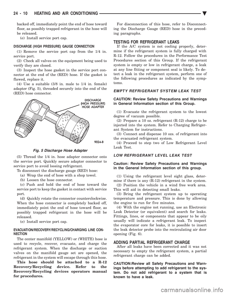
flawed, replace it. (4) Use a suitable (3/8 in. male to 1/4 in. female)
adapter (Fig. 5), threaded securely into the end of the
(RED) hose connector.
(5) Thread the 1/4 in. hose adapter connector onto
the service port. Quickly secure adapter connector to
service port to avoid loosing refrigerant. To disconnect the discharge gauge (RED) hose:(a) Wrap the end of hose with a shop towel.
(b) Loosen the hose connector.
(c) Push and hold the end of hose toward the
service port to keep the gasket in contact with service
port. (d) Quickly rotate the connector counterclockwise.
When the hose connector is completely backed off,
immediately point the end of hose toward floor, as
possibly trapped refrigerant in the hose will be
released. (e) Install service port cap.
EVACUATION/RECOVERY/RECYCLING/CHARGING LINE CON-
NECTION
The center manifold (YELLOW) or (WHITE) hose is
used to recycle, recover, evacuate, and charge the
refrigerant system. When the discharge or suction
valves on the manifold gauge set are opened, the
refrigerant in the system will escape through this hose. This hose should be attached to a R-12
Recovery/Recycling device. Refer to the
Recovery/Recycling devices operators manual
for procedures. For disconnection of this hose, refer to Disconnect-
ing the Discharge Gauge (RED) hose in the preced-
ing paragraphs.
TESTING FOR REFRIGERANT LEAKS
If the A/C system is not cooling properly, deter-
mine if the refrigerant system is fully charged with
R-12. Follow the procedures in the Performance Test
Procedures section of this Group. If the refrigerant
system is empty or low in refrigerant charge, a leak
at any line fitting or component seal is likely. To de-
tect a leak in the refrigerant system, perform one of
the following procedures as indicated by the symp-
toms.
EMPTY REFRIGERANT SYSTEM LEAK TEST
CAUTION: Review Safety Precautions and Warnings
in General Information section of this Group.
(1) Evacuate the refrigerant system to the lowest
degree of vacuum possible. (2) Prepare a 10 oz. refrigerant (R-12) charge to be
injected into the system. Refer to Charging Refriger-
ant System for instructions. (3) Connect and dispense 10 ozs. of refrigerant into
the evacuated refrigerant system. (4) Proceed to step two of Low Refrigerant Level
Leak Test.
LOW REFRIGERANT LEVEL LEAK TEST
Caution: Review Safety Precautions and Warnings
in the General Information section of this group.
(1) Using the refrigerant level sight glass, deter-
mine if there is any (R-12) refrigerant in the system. (2) Position the vehicle in a wind free work area.
This will aid in detecting small leaks. (3) Bring the refrigerant system up to operating
temperature and pressure. This is done by allowing
the engine to run for five minutes. (4) With the engine not running, use an Electronic
Leak Detector (or equivalent) and search for leaks.
Fittings, lines, or components that appear to be oily
usually will indicate a refrigerant leak. To inspect
the evaporator core for leaks, it is possible to insert
the leak detector probe into the recirculating air door
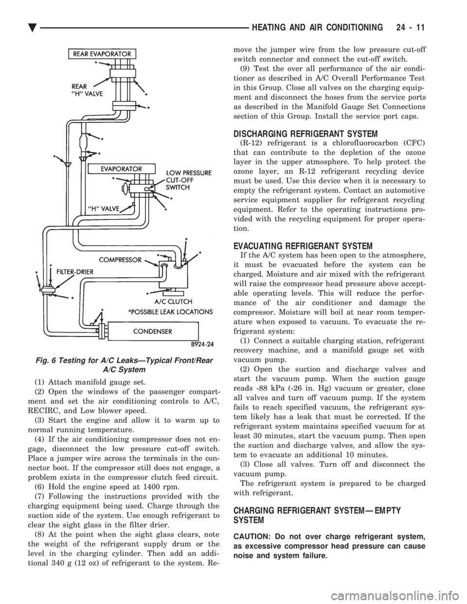
opening (Fig. 6).
ADDING PARTIAL REFRIGERANT CHARGE
After all leaks have been corrected and it was not
necessary to empty the refrigerant system, a partial
refrigerant charge can be added.
CAUTION:Review all Safety Precautions and Warn-
ings before attempting to add refrigerant to the sys-
tem. Do not add refrigerant to a system that is
known to have a leak.
Fig. 5 Discharge Hose Adapter
24 - 10 HEATING AND AIR CONDITIONING Ä
Page 2315 of 2438
(1) Attach manifold gauge set.
(2) Open the windows of the passenger compart-
ment and set the air conditioning controls to A/C,
RECIRC, and Low blower speed. (3) Start the engine and allow it to warm up to
normal running temperature. (4) If the air conditioning compressor does not en-
gage, disconnect the low pressure cut-off switch.
Place a jumper wire across the terminals in the con-
nector boot. If the compressor still does not engage, a
problem exists in the compressor clutch feed circuit. (6) Hold the engine speed at 1400 rpm.
(7) Following the instructions provided with the
charging equipment being used. Charge through the
suction side of the system. Use enough refrigerant to
clear the sight glass in the filter drier. (8) At the point when the sight glass clears, note
the weight of the refrigerant supply drum or the
level in the charging cylinder. Then add an addi-
tional 340 g (12 oz) of refrigerant to the system. Re- move the jumper wire from the low pressure cut-off
switch connector and connect the cut-off switch.
(9) Test the over all performance of the air condi-
tioner as described in A/C Overall Performance Test
in this Group. Close all valves on the charging equip-
ment and disconnect the hoses from the service ports
as described in the Manifold Gauge Set Connections
section of this Group. Install the service port caps.
DISCHARGING REFRIGERANT SYSTEM
(R-12) refrigerant is a chlorofluorocarbon (CFC)
that can contribute to the depletion of the ozone
layer in the upper atmosphere. To help protect the
ozone layer, an R-12 refrigerant recycling device
must be used. Use this device when it is necessary to
empty the refrigerant system. Contact an automotive
service equipment supplier for refrigerant recycling
equipment. Refer to the operating instructions pro-
vided with the recycling equipment for proper opera-
tion.
EVACUATING REFRIGERANT SYSTEM
If the A/C system has been open to the atmosphere,
it must be evacuated before the system can be
charged. Moisture and air mixed with the refrigerant
will raise the compressor head pressure above accept-
able operating levels. This will reduce the perfor-
mance of the air conditioner and damage the
compressor. Moisture will boil at near room temper-
ature when exposed to vacuum. To evacuate the re-
frigerant system: (1) Connect a suitable charging station, refrigerant
recovery machine, and a manifold gauge set with
vacuum pump. (2) Open the suction and discharge valves and
start the vacuum pump. When the suction gauge
reads -88 kPa (-26 in. Hg) vacuum or greater, close
all valves and turn off vacuum pump. If the system
fails to reach specified vacuum, the refrigerant sys-
tem likely has a leak that must be corrected. If the
refrigerant system maintains specified vacuum for at
least 30 minutes, start the vacuum pump. Then open
the suction and discharge valves, and allow the sys-
tem to evacuate an additional 10 minutes. (3) Close all valves. Turn off and disconnect the
vacuum pump. The refrigerant system is prepared to be charged
with refrigerant.
CHARGING REFRIGERANT SYSTEMÐEMPTY
SYSTEM
CAUTION: Do not over charge refrigerant system,
as excessive compressor head pressure can cause
noise and system failure.
Fig. 6 Testing for A/C LeaksÐTypical Front/Rear A/C System
Ä HEATING AND AIR CONDITIONING 24 - 11
Page 2316 of 2438
WARNING: REVIEW SAFETY PRECAUTIONS AND
WARNINGS BEFORE CHARGING THE REFRIGER-
ANT SYSTEM.
After the system has been tested for leaks and
evacuated, a refrigerant charge can be injected into
the system. (1) Connect manifold gauge set.
(2) Measure refrigerant (refer to capacities) and
heat to 52ÉC (125ÉF) with the charging station. Refer
to the instructions provided with the equipment be-
ing used.
REFRIGERANT CAPACITIES:
² Without Rear A/C = 907 g (32 oz.)
² With Rear A/C = 1219 g (43 oz.)
(3) Open the suction and discharge valves. Open
the charge valve to allow the heated refrigerant to
flow into the system. When the transfer of refriger-
ant has stopped, close the suction and discharge
valve. (4) If all of the refrigerant charge did not transfer
from the dispensing device, start engine and hold at
idle (1400 rpm). Set the A/C control to A/C, low
blower speed, and open windows. If the A/C compres-
sor does not engage, test the compressor clutch con-
trol circuit and correct any failure. Refer to Group
8W, Wiring Diagrams. (5) Open the suction valve to allow the remaining
refrigerant to transfer to the system.
WARNING: TAKE CARE NOT TO OPEN THE DIS-
CHARGE (HIGH-PRESSURE) VALVE AT THIS TIME.
(6) Close all valves and test the A/C system perfor-
mance. Refer to Heater and A/C Performance Tests
in this Group. (7) Disconnect the charging station or manifold
gauge set. Install the service port caps.
OIL LEVEL
It is important to have the correct amount of oil in
the A/C system to ensure proper lubrication of the
compressor. Too little oil will result in damage to the
compressor. Too much oil will reduce the cooling ca-
pacity of the system. The oil used in the compressor is a 500 SUS viscos-
ity, wax-free refrigerant oil. Only refrigerant oil of
the same type should be used to service the system.
Do not use any other oil. The oil container should be
kept tightly capped until it is ready for use, and then
tightly capped after use to prevent contamination
from dirt and moisture. Refrigerant oil will quickly
absorb any moisture it comes in contact with. It will not be necessary to check oil level in the
compressor or to add oil unless there has been an oil
loss. This may be due to a ruptured line, shaft seal leakage, leakage from the evaporator, condenser
leak, filter drier or loss of refrigerant due to a colli-
sion. Oil loss at a the leak point will be evident by
the presence of a wet, shiny surface around the leak.
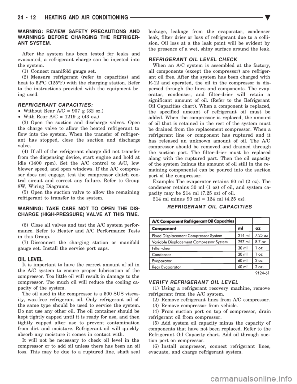
REFRIGERANT OIL LEVEL CHECK
When an A/C system is assembled at the factory,
all components (except the compressor) are refriger-
ant oil free. After the system has been charged with
R-12 and operated, the oil in the compressor is dis-
persed through the lines and components. The evap-
orator, condenser, and filter-drier will retain a
significant amount of oil. (Refer to the Refrigerant
Oil Capacities chart). When a component is replaced,
the specified amount of refrigerant oil must be
added. When the compressor is replaced, the amount
of oil that is retained in the rest of the system must
be drained from the replacement compressor. When a
refrigerant line or component has ruptured and it
has released an unknown amount of oil. The A/C
compressor should be removed and drained through
the suction port. The filter-drier must be replaced
along with the ruptured part. Then the oil capacity
of the system (minus the amount of oil still in the re-
maining components) can be poured into the suction
port of the compressor. Example: The evaporator retains 60 ml (2 oz). The
condenser retains 30 ml (1 oz) of oil, and system ca-
pacity may be 214 ml (7.25 oz) of oil. 214 ml minus 90 ml = 124 ml (4.25 oz).
VERIFY REFRIGERANT OIL LEVEL
(1) Using a refrigerant recovery machine, remove
refrigerant from the A/C system. (2) Remove refrigerant lines from A/C compressor.
(3) Remove compressor from vehicle.
(4) From suction port on top of compressor, drain
refrigerant oil from compressor. (5) Add system oil capacity minus the capacity of
components that have not been replaced. Refer to the
Refrigerant Oil Capacity chart. Add oil through suc-
tion port on compressor. (6) Install compressor, connect refrigerant lines,
evacuate, and charge refrigerant system.
REFRIGERANT OIL CAPACITIES
24 - 12 HEATING AND AIR CONDITIONING Ä