transmission CHEVROLET PLYMOUTH ACCLAIM 1993 Owner's Guide
[x] Cancel search | Manufacturer: CHEVROLET, Model Year: 1993, Model line: PLYMOUTH ACCLAIM, Model: CHEVROLET PLYMOUTH ACCLAIM 1993Pages: 2438, PDF Size: 74.98 MB
Page 610 of 2438
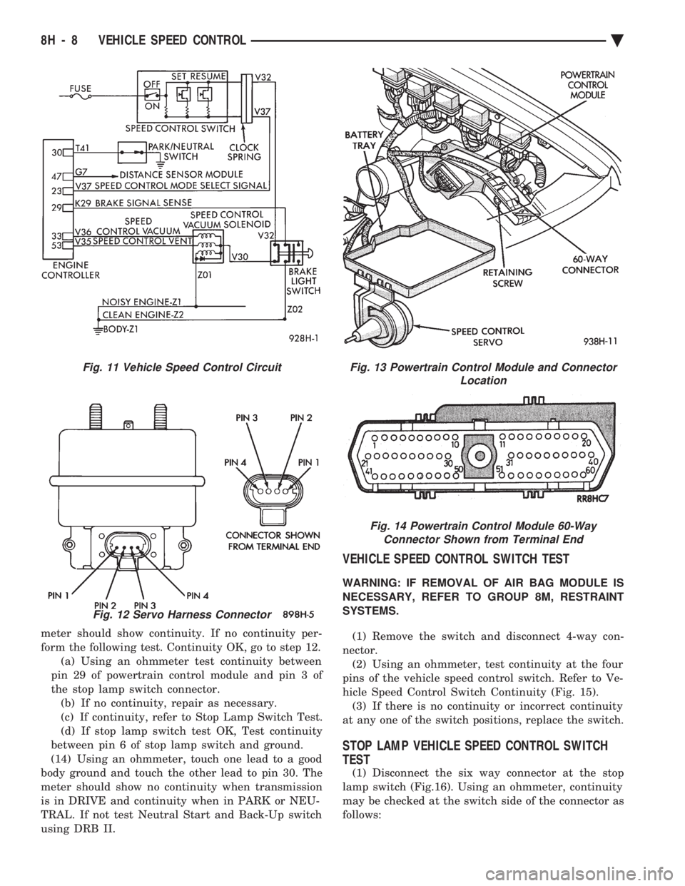
meter should show continuity. If no continuity per-
form the following test. Continuity OK, go to step 12.(a) Using an ohmmeter test continuity between
pin 29 of powertrain control module and pin 3 of
the stop lamp switch connector. (b) If no continuity, repair as necessary.
(c) If continuity, refer to Stop Lamp Switch Test.
(d) If stop lamp switch test OK, Test continuity
between pin 6 of stop lamp switch and ground.
(14) Using an ohmmeter, touch one lead to a good
body ground and touch the other lead to pin 30. The
meter should show no continuity when transmission
is in DRIVE and continuity when in PARK or NEU-
TRAL. If not test Neutral Start and Back-Up switch
using DRB II.
VEHICLE SPEED CONTROL SWITCH TEST
WARNING: IF REMOVAL OF AIR BAG MODULE IS
NECESSARY, REFER TO GROUP 8M, RESTRAINT
SYSTEMS.
(1) Remove the switch and disconnect 4-way con-
nector. (2) Using an ohmmeter, test continuity at the four
pins of the vehicle speed control switch. Refer to Ve-
hicle Speed Control Switch Continuity (Fig. 15). (3) If there is no continuity or incorrect continuity
at any one of the switch positions, replace the switch.
STOP LAMP VEHICLE SPEED CONTROL SWITCH
TEST
(1) Disconnect the six way connector at the stop
lamp switch (Fig.16). Using an ohmmeter, continuity
may be checked at the switch side of the connector as
follows:
Fig. 11 Vehicle Speed Control Circuit
Fig. 12 Servo Harness Connector
Fig. 13 Powertrain Control Module and Connector Location
Fig. 14 Powertrain Control Module 60-WayConnector Shown from Terminal End
8H - 8 VEHICLE SPEED CONTROL Ä
Page 707 of 2438
POWER SEATS
CONTENTS
page page
ADJUSTER ............................. 3
CIRCUIT BREAKER TEST .................. 1
ENTHUSIAST SEAT ....................... 4
GENERAL INFORMATION .................. 1
HARNESS VOLTAGE TEST ................. 1
HORIZONTAL AND VERTICAL TRANSMISSIONS ....................... 3
MEMORY CONTROL MODULE REPLACEMENT ....................... 19
MOTOR ................................ 3
MOTOR TESTS .......................... 1
POWER MEMORY SEAT, RECLINER AND MIRRORS ............................. 5 POWER MEMORY SEAT, RECLINER AND
MIRRORS DIAGNOSIS ................... 9
POWER RECLINER MECHANISM ........... 18
POWER RECLINER MOTOR AND CABLE ..... 17
RECLINER SWITCH REPLACEMENT ......... 19
RECLINER SWITCH TEST ................. 19
SEAT ASSEMBLY ........................ 3
SWITCH REPLACEMENT REMOVAL .......... 5
SWITCH TEST ........................... 5
SWITCH TEST ........................... 3
TEST PROCEDURES ...................... 6
TEST PROCEDURES ...................... 1
GENERAL INFORMATION
Power seats can be adjusted in six different direc-
tions up, down, forward, back, tilt forward, or tilt
rearward. A three armature permanent magnet reversible mo-
tor is coupled through cables to worm gear box assem-
blies located in the seat tracks, providing the various
seat movements. The electrical circuit is protected by a 30 amp circuit
breaker located on the fuse block.
TEST PROCEDURES
Before any testing is attempted the battery should be
carefully charged and all connections and terminals
cleaned and tightened to insure proper continuity and
grounds. With dome lamp on, apply switch in direction of
failure. If dome lamp dims the seat motor is trying to
work indicating mechanical jamming. If dome lamp
does not dim, then proceed with the following electrical
tests.
CIRCUIT BREAKER TEST
Find correct circuit breaker on fuse block. Pull out
slightly but be sure that circuit breaker terminals still
contact terminals in fuse block. Connect ground wire of
voltmeter to a good ground. With probe of voltmeter
positive wire, check both terminals of circuit breaker
for battery voltage. If only one terminal checks at
battery voltage, circuit breaker is defective and must
be replaced. If neither terminal shows battery voltage,
check for open or shorted circuit to circuit breaker.
HARNESS VOLTAGE TEST
The following test will determine whether or not
voltage is continuous through the body harness to the
switch. (1) Remove power seat switch from mounting posi-
tion and disconnect switch from wiring harness. (2) Connect one lead of test light to ground terminal,
black wire (BK) of center section, and touch other test
light lead to red wire (RD) terminal. (3) If test light comes on, harness to switch is good.
If test light does not come on, perform circuit breaker
test.
MOTOR TESTS
AA BODY
(1) Remove switch from mounting position and dis-
connect from harness. (2) To check the center motor, connect a jumper wire
between pin 5 and pin 3 (Fig. 1). Connect a second
jumper wire between pin 7 and pin 4 If motor does not
operate, reverse the jumpers, pin 5 to pin 4 and pin 7 to
pin 3. If motor still does not operate check wiring
between switch connector and motor assembly. If wir-
ing checks good replace motor assembly. (3) To check the front motor, connect a jumper wire
between pin 5 and pin 1 (Fig. 1). Connect a second
jumper wire between pin 7 and pin 8. If motor does not
operate, reverse the jumpers, pin 5 to pin 8 and pin 7 to
pin 1. If motor still does not operate check wiring
between switch connector and motor assembly. If wir-
ing checks good replace motor assembly.
(4) To check the rear motor, connect a covered jumper
wire between pin 5 and pin 6 (Fig. 1). Connect a second
Ä POWER SEATS 8R - 1
Page 709 of 2438
switch connector and motor assembly. If wiring
checks good replace motor assembly.(4) To check the rear motor, connect a jumper wire
between cavity number 3 and cavity number 4. Con-
nect a second jumper wire between cavity number 6
and cavity number 13. If the motor does not operate,
reverse the jumpers, 3 to 13 and 6 to 4. If the motor
still does not operate check the wiring between
switch connector and motor assembly. If wiring
checks good replace motor assembly. (5) If all motors and the seat operate properly, per-
form Switch Test.
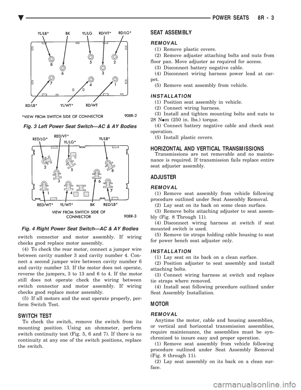
SWITCH TEST
To check the switch, remove the switch from its
mounting position. Using an ohmmeter, perform
switch continuity test (Fig. 5, 6 and 7). If there is no
continuity at any one of the switch positions, replace
the switch.
SEAT ASSEMBLY
REMOVAL
(1) Remove plastic covers.
(2) Remove adjuster attaching bolts and nuts from
floor pan. Move adjuster as required for access. (3) Disconnect battery negative cable.
(4) Disconnect wiring harness power lead at car-
pet. (5) Remove seat assembly from vehicle.
INSTALLATION
(1) Position seat assembly in vehicle.
(2) Connect wiring harness.
(3) Install and tighten mounting bolts and nuts to
28 N Im (250 in. lbs.) torque.
(4) Connect battery negative cable and check seat
operation. (5) Install plastic covers.
HORIZONTAL AND VERTICAL TRANSMISSIONS
Transmissions are not removable and no mainte-
nance is required. If transmission fails replace entire
seat adjuster assembly.
ADJUSTER
REMOVAL
(1) Remove seat assembly from vehicle following
procedure outlined under Seat Assembly Removal. (2) Lay seat on its back on some clean surface.
(3) Remove bolts attaching adjuster to seat assem-
bly (Fig. 8 Through 11). (4) Disconnect wiring harness at switch if seat
mounted switch is used. (5) Remove tie straps holding cable housing to seat
for power bench seat adjuster only.
INSTALLATION
(1) Lay seat on its back on a clean surface.
(2) Position adjuster to seat assembly and install
attaching bolts. (3) Connect wiring harness at switch and replace
tie straps where removed. (4) Install seat following procedure outlined under
Seat Assembly Installation.
MOTOR
REMOVAL
Anytime the motor, cable and housing assemblies,
or vertical and horizontal transmission assemblies,
require maintenance, the assemblies must be syn-
chronized to insure easy and proper operation. (1) Remove seat assembly from vehicle following
procedure outlined under Seat Assembly Removal
(Fig. 8 through 11). (2) Lay seat assembly on its back on a clean sur-
face.
Fig. 3 Left Power Seat SwitchÐAC & AY Bodies
Fig. 4 Right Power Seat SwitchÐAC & AY Bodies
Ä POWER SEATS 8R - 3
Page 723 of 2438
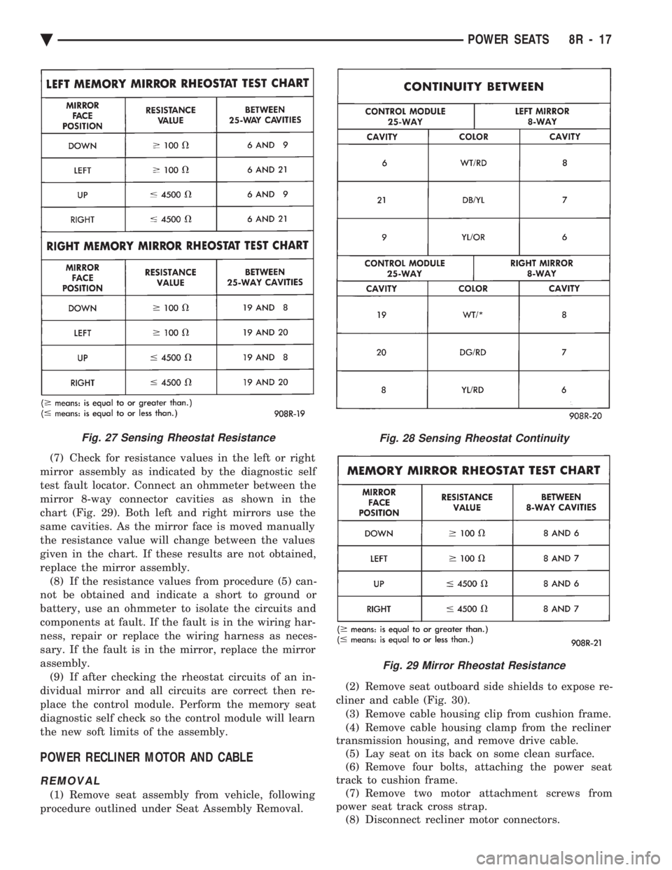
(7) Check for resistance values in the left or right
mirror assembly as indicated by the diagnostic self
test fault locator. Connect an ohmmeter between the
mirror 8-way connector cavities as shown in the
chart (Fig. 29). Both left and right mirrors use the
same cavities. As the mirror face is moved manually
the resistance value will change between the values
given in the chart. If these results are not obtained,
replace the mirror assembly. (8) If the resistance values from procedure (5) can-
not be obtained and indicate a short to ground or
battery, use an ohmmeter to isolate the circuits and
components at fault. If the fault is in the wiring har-
ness, repair or replace the wiring harness as neces-
sary. If the fault is in the mirror, replace the mirror
assembly. (9) If after checking the rheostat circuits of an in-
dividual mirror and all circuits are correct then re-
place the control module. Perform the memory seat
diagnostic self check so the control module will learn
the new soft limits of the assembly.
POWER RECLINER MOTOR AND CABLE
REMOVAL
(1) Remove seat assembly from vehicle, following
procedure outlined under Seat Assembly Removal. (2) Remove seat outboard side shields to expose re-
cliner and cable (Fig. 30). (3) Remove cable housing clip from cushion frame.
(4) Remove cable housing clamp from the recliner
transmission housing, and remove drive cable. (5) Lay seat on its back on some clean surface.
(6) Remove four bolts, attaching the power seat
track to cushion frame. (7) Remove two motor attachment screws from
power seat track cross strap. (8) Disconnect recliner motor connectors.
Fig. 27 Sensing Rheostat ResistanceFig. 28 Sensing Rheostat Continuity
Fig. 29 Mirror Rheostat Resistance
Ä POWER SEATS 8R - 17
Page 724 of 2438
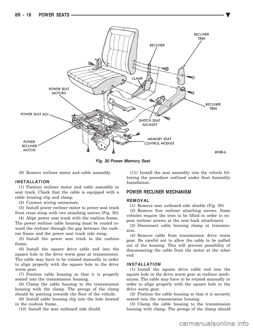
(9) Remove recliner motor and cable assembly.
INSTALLATION
(1) Position recliner motor and cable assembly to
seat track. Check that the cable is equipped with a
cable housing clip and clamp. (2) Connect wiring connectors.
(3) Install power recliner motor to power seat track
front cross strap with two attaching screws (Fig. 30). (4) Align power seat track with the cushion frame.
The power recliner cable housing must be routed to-
ward the recliner through the gap between the cush-
ion frame and the power seat track side strap. (5) Install the power seat track to the cushion
frame. (6) Install the square drive cable end into the
square hole in the drive worm gear at transmission.
The cable may have to be rotated manually in order
to align properly with the square hole in the drive
worm gear. (7) Position cable housing so that it is properly
seated into the transmission housing. (8) Clamp the cable housing to the transmission
housing with the clamp. The prongs of the clamp
should be pointing towards the floor of the vehicle. (9) Install cable housing clip into the hole located
in the cushion frame. (10) Install the seat outboard side shield. (11) Install the seat assembly into the vehicle fol-
lowing the procedure outlined under Seat Assembly
Installation.
POWER RECLINER MECHANISM
REMOVAL
(1) Remove seat outboard side shields (Fig. 30).
(2) Remove four recliner attaching screws. Some
vehicles require the trim to be lifted in order to ex-
pose recliner screws at the seat back attachment. (3) Disconnect cable housing clamp at transmis-
sion. (4) Remove cable from transmission drive worm
gear. Be careful not to allow the cable to be pulled
out of the housing. This will prevent possibility of
disconnecting the cable from the motor at the other
end.
INSTALLATION
(1) Install the square drive cable end into the
square hole in the drive worm gear at recliner mech-
anism. The cable may have to be rotated manually in
order to align properly with the square hole in the
drive worm gear. (2) Position the cable housing so that it is securely
seated into the transmission housing. (3) Clamp the cable housing to the transmission
housing with clamp. The prongs of the clamp should
Fig. 30 Power Memory Seat
8R - 18 POWER SEATS Ä
Page 743 of 2438
AUTOMATIC DAY/NIGHT INSIDE MIRROR
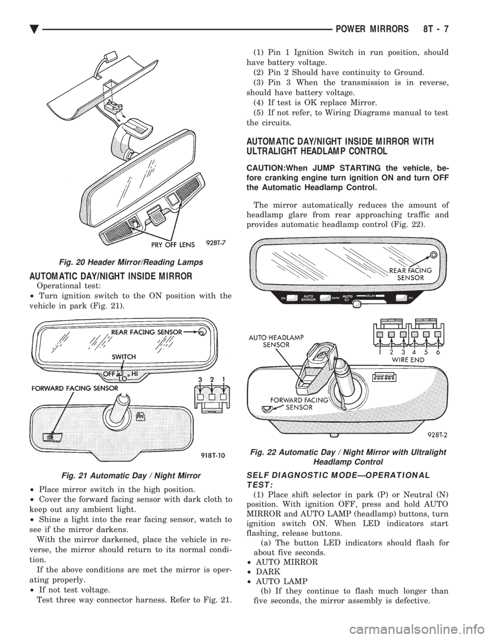
Operational test:
² Turn ignition switch to the ON position with the
vehicle in park (Fig. 21).
² Place mirror switch in the high position.
² Cover the forward facing sensor with dark cloth to
keep out any ambient light.
² Shine a light into the rear facing sensor, watch to
see if the mirror darkens. With the mirror darkened, place the vehicle in re-
verse, the mirror should return to its normal condi-
tion. If the above conditions are met the mirror is oper-
ating properly.
² If not test voltage.
Test three way connector harness. Refer to Fig. 21. (1) Pin 1 Ignition Switch in run position, should
have battery voltage. (2) Pin 2 Should have continuity to Ground.
(3) Pin 3 When the transmission is in reverse,
should have battery voltage. (4) If test is OK replace Mirror.
(5) If not refer, to Wiring Diagrams manual to test
the circuits.
AUTOMATIC DAY/NIGHT INSIDE MIRROR WITH
ULTRALIGHT HEADLAMP CONTROL
CAUTION:When JUMP STARTING the vehicle, be-
fore cranking engine turn ignition ON and turn OFF
the Automatic Headlamp Control.
The mirror automatically reduces the amount of
headlamp glare from rear approaching traffic and
provides automatic headlamp control (Fig. 22).
SELF DIAGNOSTIC MODEÐOPERATIONAL TEST:
(1) Place shift selector in park (P) or Neutral (N)
position. With ignition OFF, press and hold AUTO
MIRROR and AUTO LAMP (headlamp) buttons, turn
ignition switch ON. When LED indicators start
flashing, release buttons. (a) The button LED indicators should flash for
about five seconds.
² AUTO MIRROR
² DARK
² AUTO LAMP
(b) If they continue to flash much longer than
five seconds, the mirror assembly is defective.
Fig. 20 Header Mirror/Reading Lamps
Fig. 21 Automatic Day / Night Mirror
Fig. 22 Automatic Day / Night Mirror with Ultralight Headlamp Control
Ä POWER MIRRORS 8T - 7
Page 754 of 2438
The wiring diagrams also indicate what harness
the splice is located in. To identify the harness an
abbreviated call out is placed next to the main splice
(Fig. 6).
CONNECTORS
Connectors shown in the diagram sheets are
viewed from the terminal end unless otherwise spec-
ified. For viewing bulkhead, powertrain control mod-
ule, and transmission control module connectors refer
to the rear of the wiring diagrams. This area shows
major connectors for pin and cavity information.
TROUBLESHOOTING WIRING PROBLEMS
When troubleshooting wiring problems there are
six steps which can aid in the procedure. The steps
are listed and explained below. (1) Verify the problem.
(2) Verify any related symptoms. Perform opera-
tional checks on components that are in the same cir-
cuit as the problem area. Refer to the wiring
diagram fuse application chart. (3) Analyze the symptoms. Use the wiring dia-
grams to determine what the circuit is doing, where
the problem most likely is occurring and where the
diagnosis will continue. (4) Isolate the problem area. (5) Repair the problem.
(6) Verify proper operation. For this step check for
proper operation of all items on the circuit repaired.
Refer to the wiring diagram fuse application chart.
FUSIBLE LINKS
Vehicle wiring harnesses are equipped with fusible
links to protect the harness in the event of a short in
the system. Fusible links are color coded to indicate
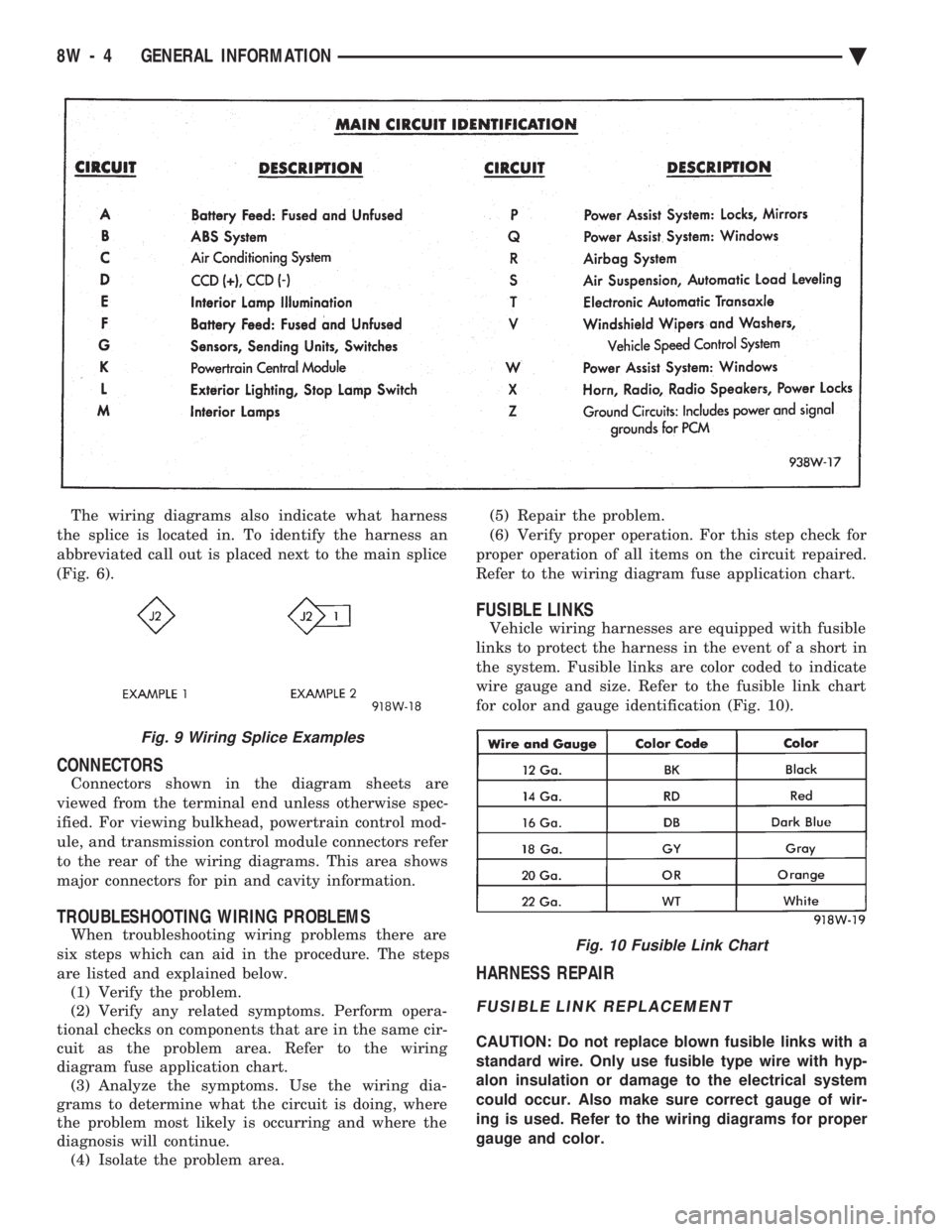
wire gauge and size. Refer to the fusible link chart
for color and gauge identification (Fig. 10).
HARNESS REPAIR
FUSIBLE LINK REPLACEMENT
CAUTION: Do not replace blown fusible links with a
standard wire. Only use fusible type wire with hyp-
alon insulation or damage to the electrical system
could occur. Also make sure correct gauge of wir-
ing is used. Refer to the wiring diagrams for proper
gauge and color.
Fig. 9 Wiring Splice Examples
Fig. 10 Fusible Link Chart
8W - 4 GENERAL INFORMATION Ä
Page 769 of 2438
WIRING AND COMPONENT IDENTIFICATION
CONTENTS
page page
AA BODY C, D, P ...................... 19
AC BODY C,D ......................... 37
AG BODY ............................. 61 AJ BODY
.............................. 77
AP BODY D, P ......................... 94
AY BODY-C ........................... 111
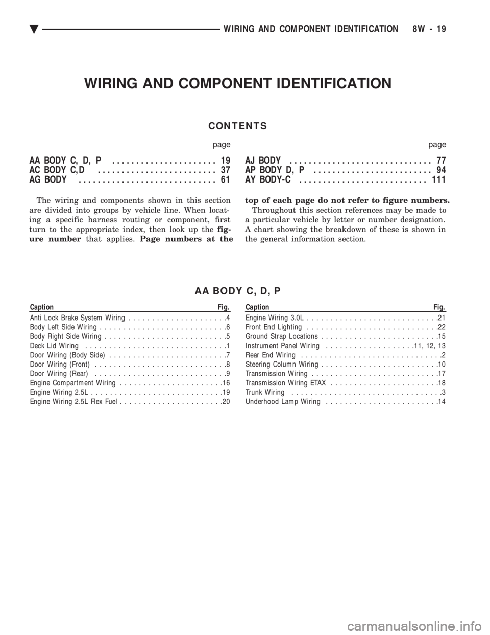
The wiring and components shown in this section
are divided into groups by vehicle line. When locat-
ing a specific harness routing or component, first
turn to the appropriate index, then look up the fig-
ure number that applies.Page numbers at the top of each page do not refer to figure numbers.
Throughout this section references may be made to
a particular vehicle by letter or number designation.
A chart showing the breakdown of these is shown in
the general information section.
AA BODY C, D, P
Caption Fig.
Anti Lock Brake System Wiring .....................4
Body Left Side Wiring ...........................6
Body Right Side Wiring ..........................5
Deck Lid Wiring ..............................1
Door Wiring (Body Side) .........................7
Door Wiring (Front) ............................8
Door Wiring (Rear) ............................9
Engine Compartment Wiring ......................16
Engine Wiring 2.5L ............................19
Engine Wiring 2.5L Flex Fuel ......................20Caption Fig.
Engine Wiring 3.0L ............................21
Front End Lighting ............................22
Ground Strap Locations .........................15
Instrument Panel Wiring .................. .11, 12, 13
Rear End Wiring ..............................2
Steering Column Wiring .........................10
Transmission Wiring ...........................17
Transmission Wiring ETAX .......................18
Trunk Wiring ................................3
Underhood Lamp Wiring ........................14
Ä WIRING AND COMPONENT IDENTIFICATION 8W - 19
Page 781 of 2438
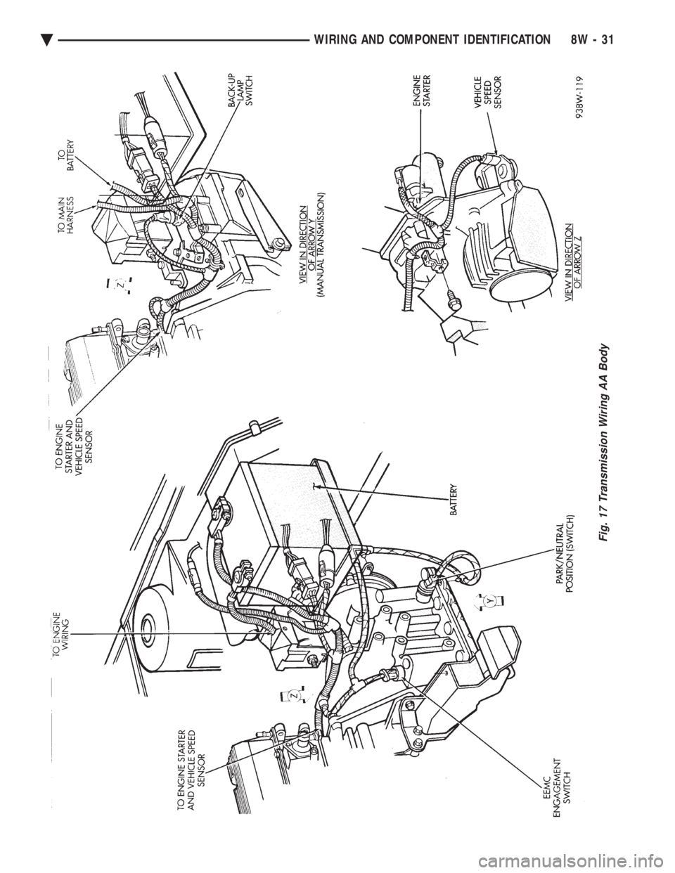
Fig. 17 Transmission Wiring AA Body
Ä WIRING AND COMPONENT IDENTIFICATION 8W - 31
Page 782 of 2438
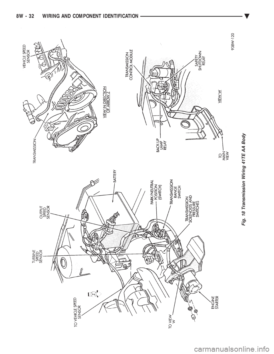
Fig. 18 Transmission Wiring 41TE AA Body
8W - 32 WIRING AND COMPONENT IDENTIFICATION Ä