CHEVROLET PLYMOUTH ACCLAIM 1993 Service Manual
Manufacturer: CHEVROLET, Model Year: 1993, Model line: PLYMOUTH ACCLAIM, Model: CHEVROLET PLYMOUTH ACCLAIM 1993Pages: 2438, PDF Size: 74.98 MB
Page 641 of 2438
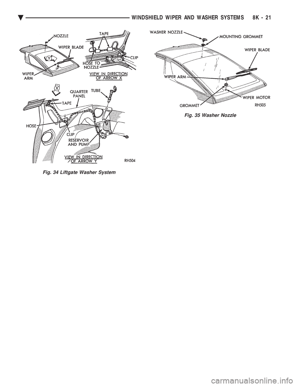
Fig. 34 Liftgate Washer System
Fig. 35 Washer Nozzle
Ä WINDSHIELD WIPER AND WASHER SYSTEMS 8K - 21
Page 642 of 2438

Page 643 of 2438
LAMPS
CONTENTS
page page
BULB APPLICATION TABLE ............... 38
CONCEALED HEADLAMPS ................ 27
EXTERIOR LAMP SWITCHES AND HEADLAMP ALIGNMENT ........................... 3
EXTERIOR LAMP SYSTEMS .............. 25
EXTERIOR LAMPSÐAA BODY ............. 7
EXTERIOR LAMPSÐAC BODY ............ 10 EXTERIOR LAMPSÐAG BODY
............ 14
EXTERIOR LAMPSÐAJ BODY ............ 16
EXTERIOR LAMPSÐAP BODY ............ 19
EXTERIOR LAMPSÐAY-BODY ............ 22
GENERAL INFORMATION .................. 1
ILLUMINATED ENTRY SYSTEM ........... 33
GENERAL INFORMATION
Each vehicle is equipped with lamps used for illumi-
nating and indicating purposes. A circuit must have a
good ground to be complete. Circuit ground occurs
when the lamp socket makes contact with the metal
body. On vehicles with plastic lamps, a wire between
the socket and the body makes the grounds. When changing lamp bulbs, check the socket for
corrosion. If corrosion is present, clean contacts with a
wire brush and coat the inside of the socket with
Mopar tMulti-purpose Grease or equivalent.
CAUTION: Do not touch the glass of halogen bulbs
with fingers or any possibly oily surface, reduced
bulb life will result.
BODY IDENTIFICATION
Throughout this Group, references are made to the
vehicle family or body code. To decode the vehicle
identification plates, refer to the Introduction Section
at the front of this manual.
DIAGNOSTIC PROCEDURES
Begin electrical system failure diagnosis by testing
all related fuses and circuit breakers in the fuse block
and engine compartment. When a vehicle experiences problems with the head-
lamp system, verify the condition of the battery con-
nections, charging system, headlamp bulbs, wire con-
nectors, relay, high beam dimmer switch and headlamp
switch. Refer to Wiring Diagrams manual for compo-
nent locations and circuit information.
SYMPTOM
Headlamps are dim when engine is idling of
with ignition turned OFF. Canada cars must
have lamps ON. ACTION
² Clean battery terminal clamps and posts. Refer to
Group 8B, Battery/Starter/Generator Service for
proper procedures.
² Test charging system output. Refer to Group 8A,
Battery/Starting/Charging Systems Diagnostics for
proper testing procedures.
² Test for high resistance in headlamp circuits.
² Defective headlamp bulb.
SYMPTOM
Bulbs burn out frequently.
ACTION
² Test charging system output. Refer to Group 8A,
Battery/Starting/Charging Systems Diagnostics for
proper testing procedures.
² Check for loose or corroded connector terminals or
splices in headlamp circuits. Refer to Wiring Diagrams
manual for component and splice locations.
SYMPTOM
Headlamps are dim with engine running above
idle. Canada cars must have lamps ON.
ACTION
² Test charging system output. Refer to Group 8A,
Battery/Starting/Charging Systems Diagnostics for
proper testing procedures.
² Test for high resistance in headlamp circuits.
² Defective headlamp bulb.
SYMPTOM
Headlamps flash randomly.
ACTION
² Test for poor circuit ground.
² Test for high resistance in headlamp circuits.
Ä LAMPS 8L - 1
Page 644 of 2438
² Test condition of headlamp relay.
² Check for loose or corroded connector terminals or
splices in headlamp circuits. Refer to Wiring Dia-
grams manual for component and splice locations.
SYMPTOM
Headlamps do not illuminate.
ACTION
² Test for voltage at headlamp bulbs connectors.
² Test headlamp relay.
² Test headlamp switch.
² Test high-beam headlamp dimmer switch.
² Check for loose or corroded connector terminals or
splices in headlamp circuits. Refer to Wiring Dia-
grams manual for component and splice locations.
FOG LAMP DIAGNOSIS
The fog lamp system receives voltage from the
headlamp relay when the low-beam headlamps are turned ON. The high-beam headlamp dimmer switch
when actuated cancels out voltage feed to the fog
lamp circuit. The fog lamp circuit is protected by a
20 amp fuse located in the fuse panel. Refer to Wir-
ing Diagrams manual for component location and cir-
cuit information.
SYMPTOM
Fog lamps do not illuminate.
ACTION
² Test fog lamp bulb.
² Test for voltage at fog lamp connector.
² Test for proper fog lamp ground.
² Test circuit fuse.
² Test fog lamp switch.
² Test high-beam headlamp dimmer switch.
² Test headlamp relay.
² Test for open circuit in wire harness.
8L - 2 LAMPS Ä
Page 645 of 2438
EXTERIOR LAMP SWITCHES AND HEADLAMP ALIGNMENT INDEX
page page
Headlamp Adjustment Using Alignment Screen .... 3
Headlamp Alignment ....................... 3
Headlamp Alignment Preparation .............. 3 Headlamp Dimmer Switch
................... 3
Headlamp Switch .......................... 3
HEADLAMP SWITCH
Service procedures for the headlamp switch can be
found in Group 8E, Instrument Panel and Gauges. More
information can be found in Wiring Diagrams manual.
HEADLAMP DIMMER SWITCH
The headlamp dimmer switch is incorporated into
the turn signal switch. Proper procedures can be found
in Group 8J, Turn Signal and Flashers. More informa-
tion can be found in Group 8W, Wiring Diagrams.
HEADLAMP ALIGNMENT
Headlamps can be aligned using the screen method
provided in this section. Alignment Tool C4466-A or
equivalent can also be used. Refer to instructions
provided with the tool for proper procedures. The
preferred headlamp alignment setting is 0 for the
left/right adjustment and 0 for the up/down ad-
justment.
HEADLAMP ALIGNMENT PREPARATION
(1) Verify headlamp dimmer switch and high beam
indicator operation. (2) Inspect and correct damaged or defective compo-
nents that could interfere with proper headlamp align-
ment. (3) Verify proper tire inflation.
(4) Clean headlamp lenses.
(5) Verify that luggage area is not heavily loaded.
(6) Fuel tank should be FULL. Add 2.94 kg (6.5 lbs.)
of weight over the fuel tank for each estimated gallon of
missing fuel.
HEADLAMP ADJUSTMENT USING ALIGNMENT
SCREEN
ALIGNMENT SCREEN PREPARATION (FIG. 1 AND 2)
(1) Position vehicle on a level surface perpendicular
to a flat wall 7.62 meters (25 ft) away from front of
headlamp lens. (2) If necessary, tape a line on the floor 7.62 meters
(25 ft) away from and parallel to the wall.
(3) From the floor up 1.27 meters (5 ft), tape a line on
the wall at the centerline of the vehicle. Sight along the
centerline of the vehicle (from rear of vehicle forward) to
verify accuracy of the line placement.
(4) Rock vehicle side-to-side three times to allow
suspension to stabilize. (5) Jounce front suspension three times by pushing
downward on front bumper and releasing. (6) Measure the distance from the center of head-
lamp lens to the floor. Transfer measurement to the
alignment screen (with tape). Use this line for up/down
adjustment reference. (7) Measure distance from the centerline of the ve-
hicle to the center of each headlamp being aligned.
Transfer measurements to screen (with tape) to each
side of vehicle centerline. Use these lines for left/right
adjustment reference.
HEADLAMP ADJUSTMENT (FIG. 3, 4, 5, 6 OR 7)
A properly aimed low beam headlamp will project the
top edge of low beam hot spot on the alignment screen
from 50 mm (2 in.) above to 50 mm (2 in.) below the
headlamp centerline. The side-to-side left edge of low
beam hot spot should be from 50 mm (2 in.) left to
50mm (2 in.) right of headlamp centerline (Fig. 1). The
preferred headlamp alignment is 0 for the
up/down adjustment and 0 for the left/right ad-
justment. The high beams on a vehicle with aero
headlamps cannot be aligned. The high beam pattern
should be correct when the low beams are aligned
properly. To adjust headlamp alignment, rotate alignment
screws to achieve the specified low beam hot spot
pattern.
CAUTION: Do not cover an illuminated headlamp for
more then 15 seconds. Lamp will overheat and burn
or melt cover.
To adjust headlamps, rotate alignment screws to
achieve the specified high intensity pattern (Fig. 1 or
2).
FOG LAMP ALIGNMENT (FIG. 8)
Prepare an alignment screen. Refer to Alignment
Screen Preparation paragraph in this section. A prop-
erly aligned fog lamp will project a pattern on the
alignment screen 100 mm (4 in.) below the fog lamp
centerline and straight ahead.
Ä LAMPS 8L - 3
Page 646 of 2438
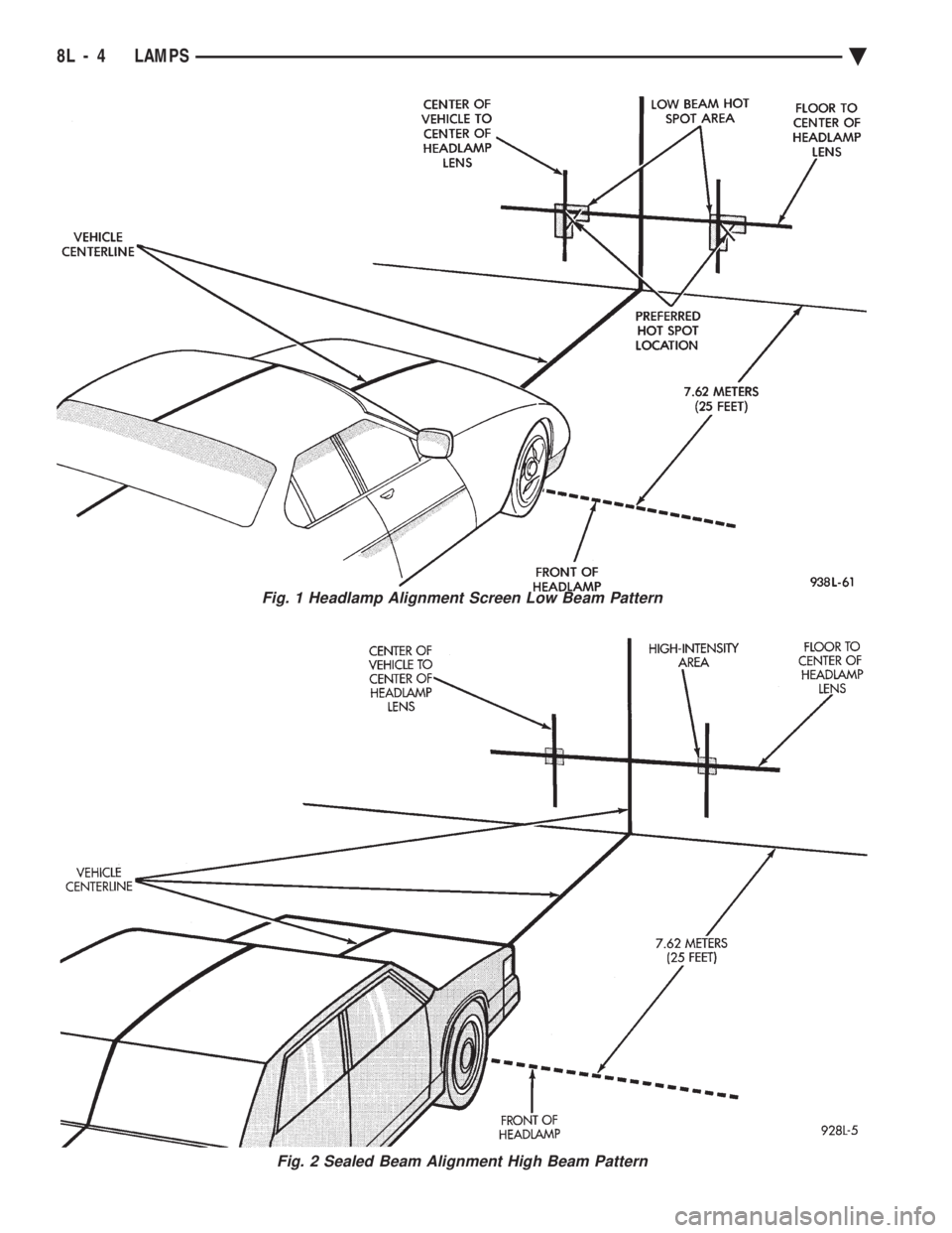
Fig. 1 Headlamp Alignment Screen Low Beam Pattern
Fig. 2 Sealed Beam Alignment High Beam Pattern
8L - 4 LAMPS Ä
Page 647 of 2438
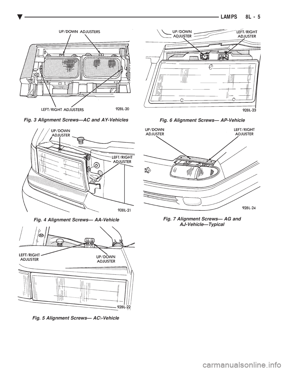
Fig. 3 Alignment ScrewsÐAC and AY-Vehicles
Fig. 4 Alignment ScrewsÐ AA-Vehicle
Fig. 5 Alignment ScrewsÐ AC\-Vehicle
Fig. 6 Alignment ScrewsÐ AP-Vehicle
Fig. 7 Alignment ScrewsÐ AG and AJ-VehicleÐTypical
Ä LAMPS 8L - 5
Page 648 of 2438
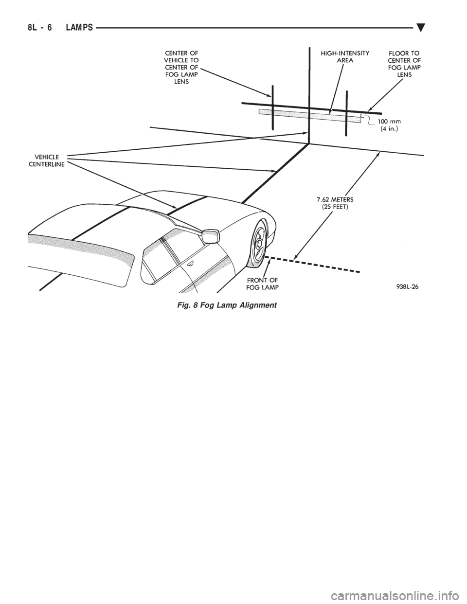
Fig. 8 Fog Lamp Alignment
8L - 6 LAMPS Ä
Page 649 of 2438
EXTERIOR LAMPSÐAA BODY INDEX
page page
Center High-Mounted Stop Lamp (CHMSL) Bulb . . 9
Fog Lamp ............................... 9
Fog Lamp Bulb ........................... 9
Front Side Marker Lamp or Bulb .............. 7
Headlamp Bulb ........................... 7 Headlamp Lens
........................... 7
License Plate Lamp or BulbÐAA/P Body ....... 8
License Plate LampsÐAA/C Body ............. 8
Park and Turn Signal Lamp or Bulb ........... 7
Tail, Stop and Turn Signal and Back-Up Lamp . . . 8
HEADLAMP BULB
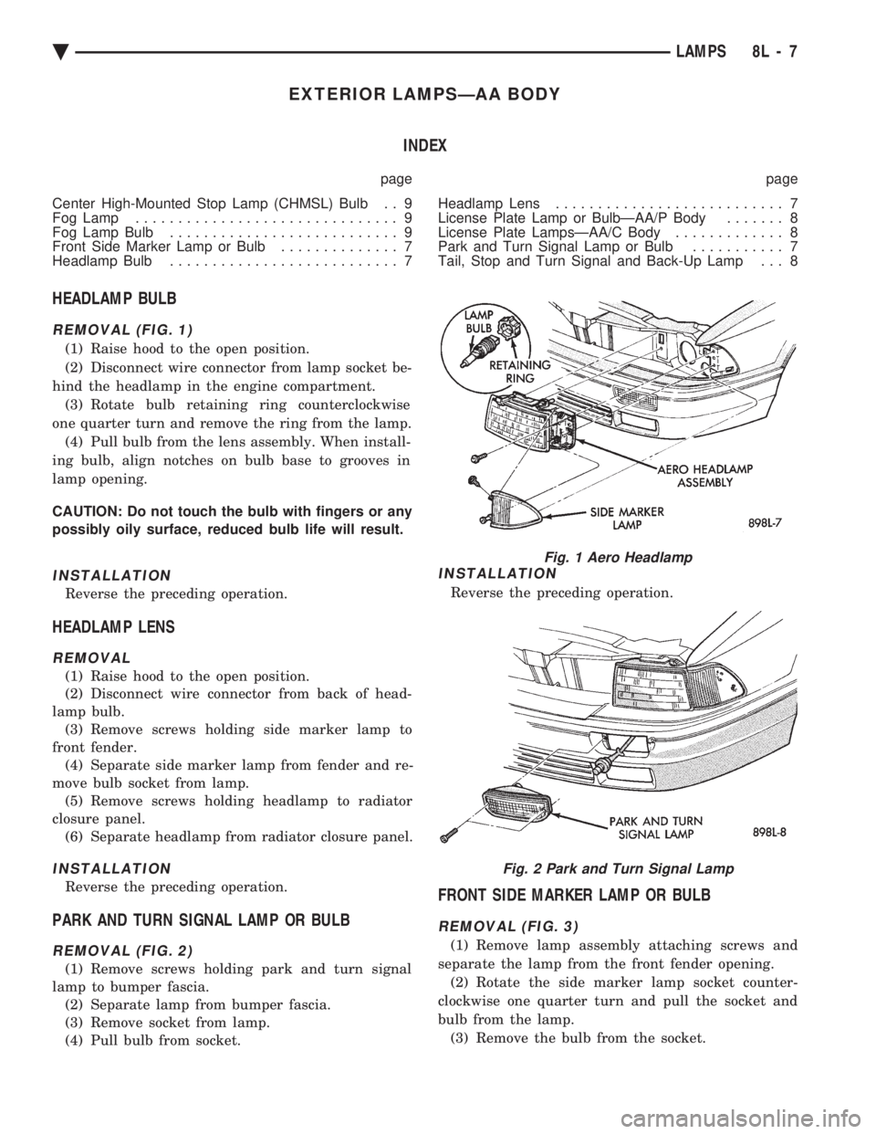
REMOVAL (FIG. 1)
(1) Raise hood to the open position.
(2) Disconnect wire connector from lamp socket be-
hind the headlamp in the engine compartment. (3) Rotate bulb retaining ring counterclockwise
one quarter turn and remove the ring from the lamp. (4) Pull bulb from the lens assembly. When install-
ing bulb, align notches on bulb base to grooves in
lamp opening.
CAUTION: Do not touch the bulb with fingers or any
possibly oily surface, reduced bulb life will result.
INSTALLATION
Reverse the preceding operation.
HEADLAMP LENS
REMOVAL
(1) Raise hood to the open position.
(2) Disconnect wire connector from back of head-
lamp bulb. (3) Remove screws holding side marker lamp to
front fender. (4) Separate side marker lamp from fender and re-
move bulb socket from lamp. (5) Remove screws holding headlamp to radiator
closure panel. (6) Separate headlamp from radiator closure panel.
INSTALLATION
Reverse the preceding operation.
PARK AND TURN SIGNAL LAMP OR BULB
REMOVAL (FIG. 2)
(1) Remove screws holding park and turn signal
lamp to bumper fascia. (2) Separate lamp from bumper fascia.
(3) Remove socket from lamp.
(4) Pull bulb from socket.
INSTALLATION
Reverse the preceding operation.
FRONT SIDE MARKER LAMP OR BULB
REMOVAL (FIG. 3)
(1) Remove lamp assembly attaching screws and
separate the lamp from the front fender opening. (2) Rotate the side marker lamp socket counter-
clockwise one quarter turn and pull the socket and
bulb from the lamp. (3) Remove the bulb from the socket.
Fig. 1 Aero Headlamp
Fig. 2 Park and Turn Signal Lamp
Ä LAMPS 8L - 7
Page 650 of 2438
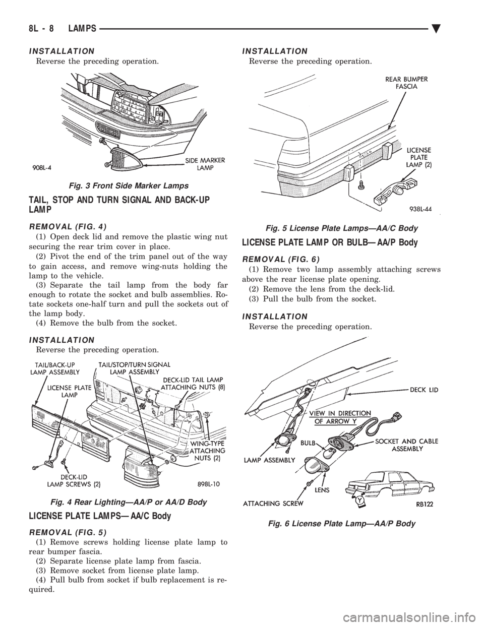
INSTALLATION
Reverse the preceding operation.
TAIL, STOP AND TURN SIGNAL AND BACK-UP
LAMP
REMOVAL (FIG. 4)
(1) Open deck lid and remove the plastic wing nut
securing the rear trim cover in place. (2) Pivot the end of the trim panel out of the way
to gain access, and remove wing-nuts holding the
lamp to the vehicle. (3) Separate the tail lamp from the body far
enough to rotate the socket and bulb assemblies. Ro-
tate sockets one-half turn and pull the sockets out of
the lamp body. (4) Remove the bulb from the socket.
INSTALLATION
Reverse the preceding operation.
LICENSE PLATE LAMPSÐAA/C Body
REMOVAL (FIG. 5)
(1) Remove screws holding license plate lamp to
rear bumper fascia. (2) Separate license plate lamp from fascia.
(3) Remove socket from license plate lamp.
(4) Pull bulb from socket if bulb replacement is re-
quired.
INSTALLATION
Reverse the preceding operation.
LICENSE PLATE LAMP OR BULBÐAA/P Body
REMOVAL (FIG. 6)
(1) Remove two lamp assembly attaching screws
above the rear license plate opening. (2) Remove the lens from the deck-lid.
(3) Pull the bulb from the socket.
INSTALLATION
Reverse the preceding operation.
Fig. 3 Front Side Marker Lamps
Fig. 4 Rear LightingÐAA/P or AA/D Body
Fig. 5 License Plate LampsÐAA/C Body
Fig. 6 License Plate LampÐAA/P Body
8L - 8 LAMPS Ä