CHEVROLET PLYMOUTH ACCLAIM 1993 Service Manual
Manufacturer: CHEVROLET, Model Year: 1993, Model line: PLYMOUTH ACCLAIM, Model: CHEVROLET PLYMOUTH ACCLAIM 1993Pages: 2438, PDF Size: 74.98 MB
Page 671 of 2438
PROBLEM
Headlamp door or doors fit poorly, rattle, or bang
when coming open or closed.
CHECK:
² Headlamp door fascia mounting bracket or adjust-
able stops for improper alignment.
² Headlamp door pivot brackets or door/crank lateral
adjustment for improperly aligned collar.
² For missing or worn pivot bushings.
² For defective motor.
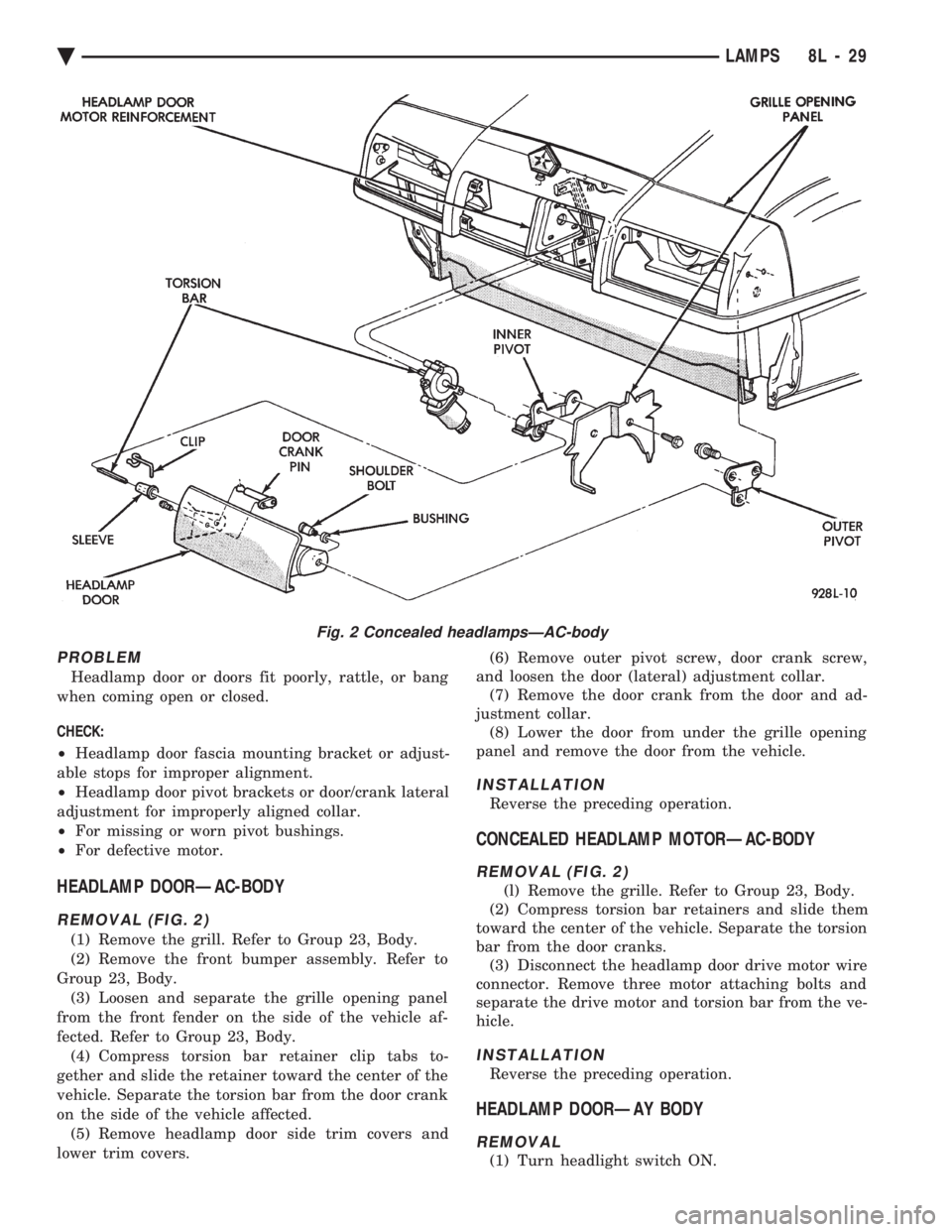
HEADLAMP DOORÐAC-BODY
REMOVAL (FIG. 2)
(1) Remove the grill. Refer to Group 23, Body.
(2) Remove the front bumper assembly. Refer to
Group 23, Body. (3) Loosen and separate the grille opening panel
from the front fender on the side of the vehicle af-
fected. Refer to Group 23, Body. (4) Compress torsion bar retainer clip tabs to-
gether and slide the retainer toward the center of the
vehicle. Separate the torsion bar from the door crank
on the side of the vehicle affected. (5) Remove headlamp door side trim covers and
lower trim covers. (6) Remove outer pivot screw, door crank screw,
and loosen the door (lateral) adjustment collar. (7) Remove the door crank from the door and ad-
justment collar. (8) Lower the door from under the grille opening
panel and remove the door from the vehicle.
INSTALLATION
Reverse the preceding operation.
CONCEALED HEADLAMP MOTORÐAC-BODY
REMOVAL (FIG. 2)
(l) Remove the grille. Refer to Group 23, Body.
(2) Compress torsion bar retainers and slide them
toward the center of the vehicle. Separate the torsion
bar from the door cranks. (3) Disconnect the headlamp door drive motor wire
connector. Remove three motor attaching bolts and
separate the drive motor and torsion bar from the ve-
hicle.
INSTALLATION
Reverse the preceding operation.
HEADLAMP DOORÐAY BODY
REMOVAL
(1) Turn headlight switch ON.
Fig. 2 Concealed headlampsÐAC-body
Ä LAMPS 8L - 29
Page 672 of 2438
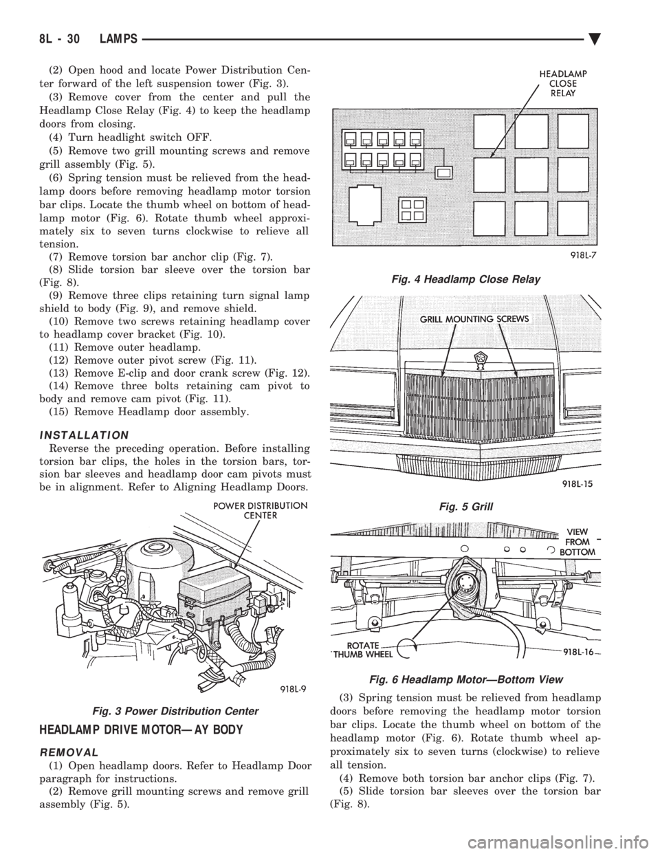
(2) Open hood and locate Power Distribution Cen-
ter forward of the left suspension tower (Fig. 3). (3) Remove cover from the center and pull the
Headlamp Close Relay (Fig. 4) to keep the headlamp
doors from closing. (4) Turn headlight switch OFF.
(5) Remove two grill mounting screws and remove
grill assembly (Fig. 5). (6) Spring tension must be relieved from the head-
lamp doors before removing headlamp motor torsion
bar clips. Locate the thumb wheel on bottom of head-
lamp motor (Fig. 6). Rotate thumb wheel approxi-
mately six to seven turns clockwise to relieve all
tension. (7) Remove torsion bar anchor clip (Fig. 7).
(8) Slide torsion bar sleeve over the torsion bar
(Fig. 8). (9) Remove three clips retaining turn signal lamp
shield to body (Fig. 9), and remove shield. (10) Remove two screws retaining headlamp cover
to headlamp cover bracket (Fig. 10). (11) Remove outer headlamp.
(12) Remove outer pivot screw (Fig. 11).
(13) Remove E-clip and door crank screw (Fig. 12).
(14) Remove three bolts retaining cam pivot to
body and remove cam pivot (Fig. 11). (15) Remove Headlamp door assembly.
INSTALLATION
Reverse the preceding operation. Before installing
torsion bar clips, the holes in the torsion bars, tor-
sion bar sleeves and headlamp door cam pivots must
be in alignment. Refer to Aligning Headlamp Doors.
HEADLAMP DRIVE MOTORÐAY BODY
REMOVAL
(1) Open headlamp doors. Refer to Headlamp Door
paragraph for instructions. (2) Remove grill mounting screws and remove grill
assembly (Fig. 5). (3) Spring tension must be relieved from headlamp
doors before removing the headlamp motor torsion
bar clips. Locate the thumb wheel on bottom of the
headlamp motor (Fig. 6). Rotate thumb wheel ap-
proximately six to seven turns (clockwise) to relieve
all tension. (4) Remove both torsion bar anchor clips (Fig. 7).
(5) Slide torsion bar sleeves over the torsion bar
(Fig. 8).
Fig. 3 Power Distribution Center
Fig. 4 Headlamp Close Relay
Fig. 5 Grill
Fig. 6 Headlamp MotorÐBottom View
8L - 30 LAMPS Ä
Page 673 of 2438
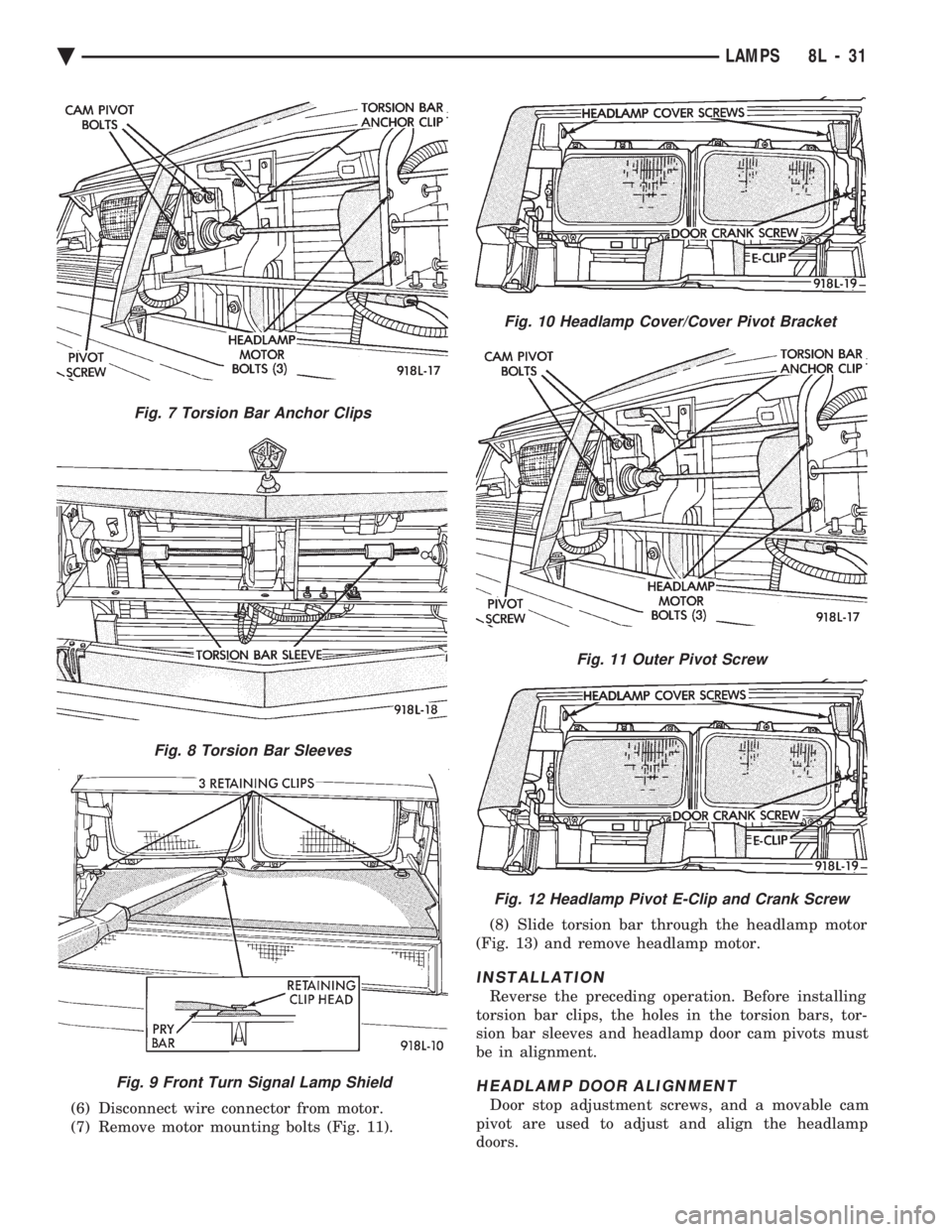
(6) Disconnect wire connector from motor.
(7) Remove motor mounting bolts (Fig. 11). (8) Slide torsion bar through the headlamp motor
(Fig. 13) and remove headlamp motor.
INSTALLATION
Reverse the preceding operation. Before installing
torsion bar clips, the holes in the torsion bars, tor-
sion bar sleeves and headlamp door cam pivots must
be in alignment.
HEADLAMP DOOR ALIGNMENT
Door stop adjustment screws, and a movable cam
pivot are used to adjust and align the headlamp
doors.
Fig. 9 Front Turn Signal Lamp Shield
Fig. 10 Headlamp Cover/Cover Pivot Bracket
Fig. 7 Torsion Bar Anchor Clips
Fig. 8 Torsion Bar Sleeves
Fig. 11 Outer Pivot Screw
Fig. 12 Headlamp Pivot E-Clip and Crank Screw
Ä LAMPS 8L - 31
Page 674 of 2438
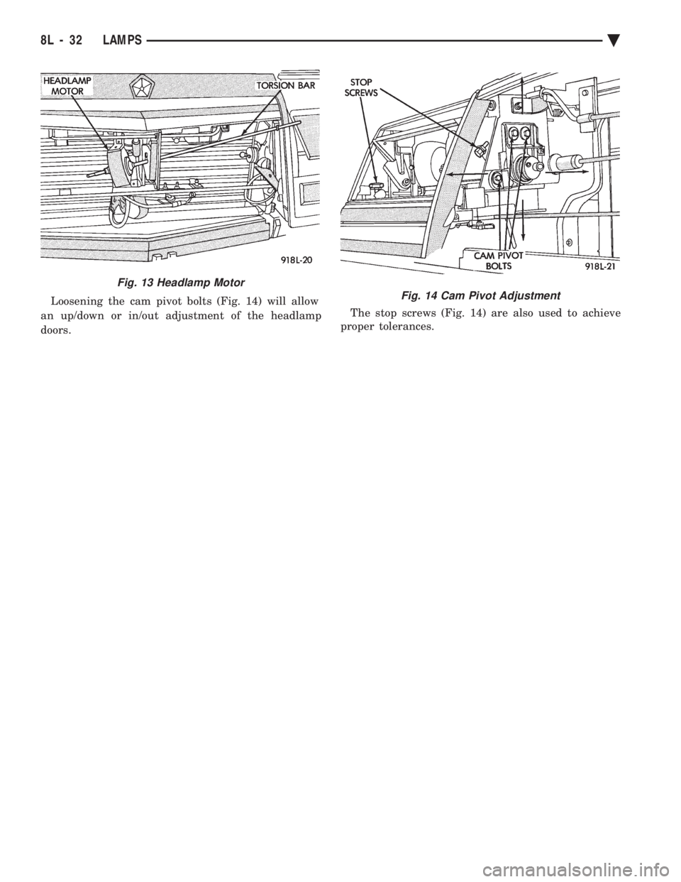
Loosening the cam pivot bolts (Fig. 14) will allow
an up/down or in/out adjustment of the headlamp
doors. The stop screws (Fig. 14) are also used to achieve
proper tolerances.
Fig. 13 Headlamp Motor
Fig. 14 Cam Pivot Adjustment
8L - 32 LAMPS Ä
Page 675 of 2438
ILLUMINATED ENTRY SYSTEM INDEX
page page
Body Controller ComputerÐAC, AG, AJ and AY-Body ............................. 34
Diagnostic ProceduresÐAA-Body ............ 33 Diagnostic ProceduresÐAC, AG, AJ and AY-Body . 33
General Information ....................... 33
Illuminated Entry ModuleÐAA-Body ........... 34
GENERAL INFORMATION
AA-BODY
The Illuminated Entry System (on AA Body) actu-
ates the interior courtesy and/or dome lamps (except
for the illuminated ignition switch) by lifting either
front door exterior handle. Lamp illumination is terminated 35 seconds ( 68
seconds later when battery voltage is normal), or by
turning the ignition switch to the run position,
whichever occurs first. When testing the system, all
vehicle doors must be closed to prevent the door jam
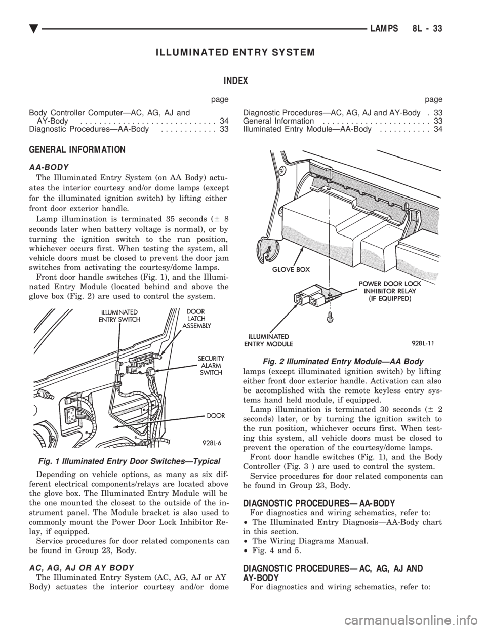
switches from activating the courtesy/dome lamps. Front door handle switches (Fig. 1), and the Illumi-
nated Entry Module (located behind and above the
glove box (Fig. 2) are used to control the system.
Depending on vehicle options, as many as six dif-
ferent electrical components/relays are located above
the glove box. The Illuminated Entry Module will be
the one mounted the closest to the outside of the in-
strument panel. The Module bracket is also used to
commonly mount the Power Door Lock Inhibitor Re-
lay, if equipped. Service procedures for door related components can
be found in Group 23, Body.
AC, AG, AJ OR AY BODY
The Illuminated Entry System (AC, AG, AJ or AY
Body) actuates the interior courtesy and/or dome lamps (except illuminated ignition switch) by lifting
either front door exterior handle. Activation can also
be accomplished with the remote keyless entry sys-
tems hand held module, if equipped. Lamp illumination is terminated 30 seconds ( 62
seconds) later, or by turning the ignition switch to
the run position, whichever occurs first. When test-
ing this system, all vehicle doors must be closed to
prevent the operation of the courtesy/dome lamps. Front door handle switches (Fig. 1), and the Body
Controller (Fig . 3 ) are used to control the system.
Service procedures for door related components can
be found in Group 23, Body.
DIAGNOSTIC PROCEDURESÐAA-BODY
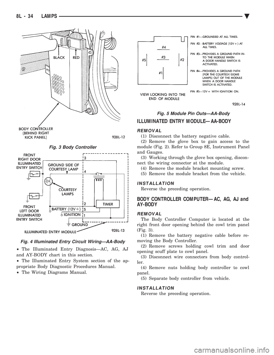
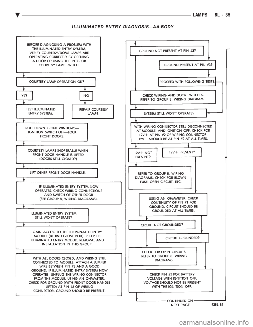
For diagnostics and wiring schematics, refer to:
² The Illuminated Entry DiagnosisÐAA-Body chart
in this section.
² The Wiring Diagrams Manual.
² Fig. 4 and 5.
DIAGNOSTIC PROCEDURESÐAC, AG, AJ AND
AY-BODY
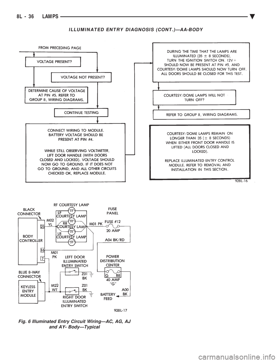
For diagnostics and wiring schematics, refer to:
Fig. 1 Illuminated Entry Door SwitchesÐTypical
Fig. 2 Illuminated Entry ModuleÐAA Body
Ä LAMPS 8L - 33
Page 676 of 2438
² The Illuminated Entry DiagnosisÐAC, AG, AJ
and AY-BODY chart in this section.
² The Illuminated Entry System section of the ap-
propriate Body Diagnostic Procedures Manual.
² The Wiring Diagrams Manual.
ILLUMINATED ENTRY MODULEÐAA-BODY
REMOVAL
(1) Disconnect the battery negative cable.
(2) Remove the glove box to gain access to the
module (Fig. 2). Refer to Group 8E, Instrument Panel
and Gauges. (3) Working through the glove box opening, discon-
nect the wiring connector at the module. (4) Remove the module bracket mounting screw.
(5) Remove the module bracket from the vehicle.
INSTALLATION
Reverse the preceding operation.
BODY CONTROLLER COMPUTERÐAC, AG, AJ and
AY-BODY
REMOVAL
The Body Controller Computer is located at the
right front door opening behind the cowl trim panel
(Fig. 3). (1) Remove the battery negative cable before re-
moving the Body Controller. (2) Remove screws holding cowl trim and door
opening scuff plate to cowl panel. (3) Disconnect wire connectors from body control-
ler. (4) Remove nuts holding body controller to cowl
panel. (5) Separate body controller from vehicle.
INSTALLATION
Reverse the preceding operation.
Fig. 3 Body Controller
Fig. 4 Illuminated Entry Circuit WiringÐAA-Body
Fig. 5 Module Pin OutsÐAA-Body
8L - 34 LAMPS Ä
Page 677 of 2438
ILLUMINATED ENTRY DIAGNOSISÐAA-BODY
Ä LAMPS 8L - 35
Page 678 of 2438
ILLUMINATED ENTRY DIAGNOSIS (CONT.)ÐAA-BODY
Fig. 6 Illuminated Entry Circuit WiringÐAC, AG, AJ and AY- BodyÐTypical
8L - 36 LAMPS Ä
Page 679 of 2438
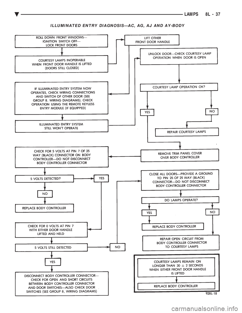
ILLUMINATED ENTRY DIAGNOSISÐAC, AG, AJ AND AY-BODY
Ä LAMPS 8L - 37
Page 680 of 2438
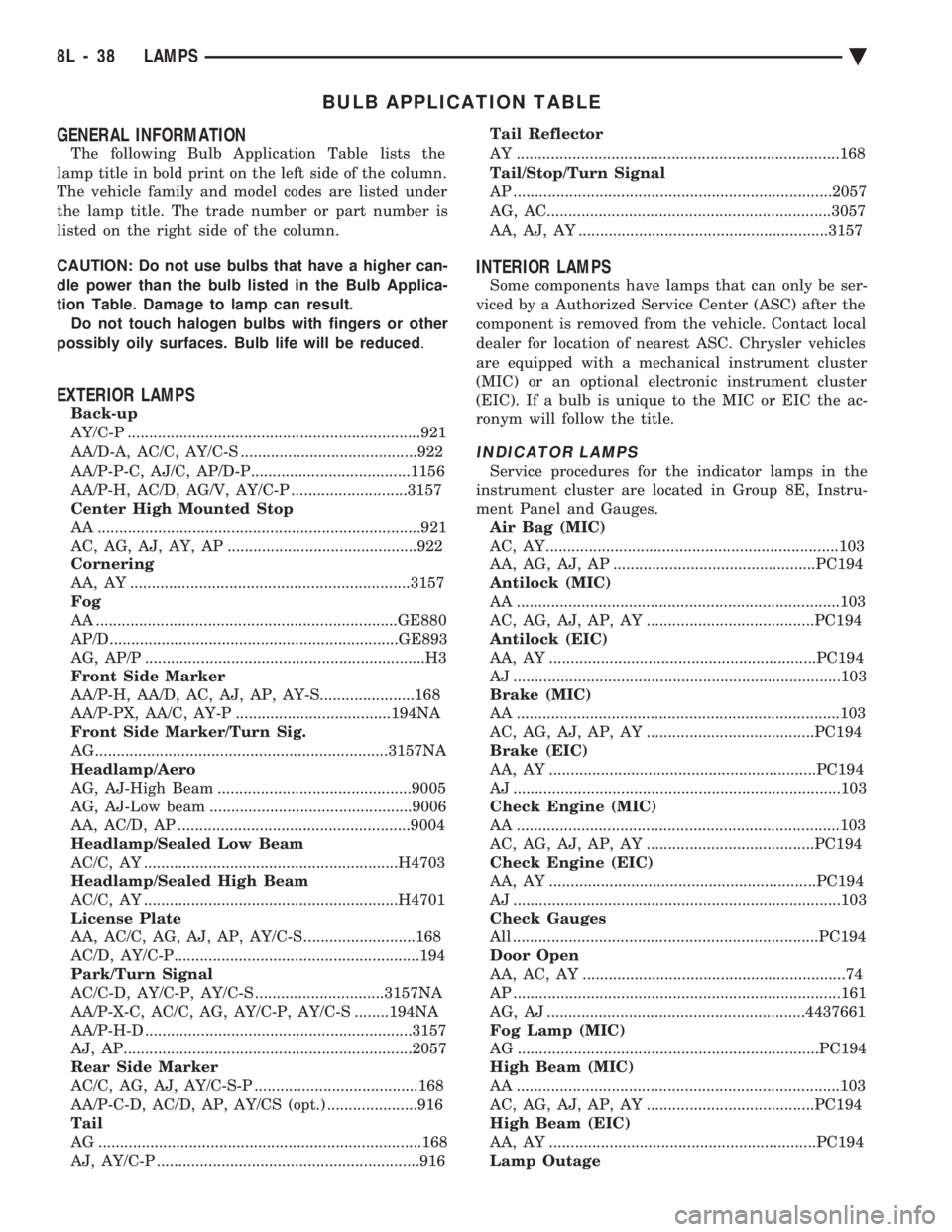
BULB APPLICATION TABLE
GENERAL INFORMATION
The following Bulb Application Table lists the
lamp title in bold print on the left side of the column.
The vehicle family and model codes are listed under
the lamp title. The trade number or part number is
listed on the right side of the column.
CAUTION: Do not use bulbs that have a higher can-
dle power than the bulb listed in the Bulb Applica-
tion Table. Damage to lamp can result. Do not touch halogen bulbs with fingers or other
possibly oily surfaces. Bulb life will be reduced .
EXTERIOR LAMPS
Back-up
AY/C-P ....................................................................921
AA/D-A, AC/C, AY/C-S .........................................922
AA/P-P-C, AJ/C, AP/D-P.....................................1156
AA/P-H, AC/D, AG/V, AY/C-P ...........................3157
Center High Mounted Stop
AA ...........................................................................921
AC, AG, AJ, AY, AP ............................................922
Cornering
AA, AY .................................................................3157
Fog
AA ......................................................................GE880
AP/D...................................................................GE893
AG, AP/P .................................................................H3
Front Side Marker
AA/P-H, AA/D, AC, AJ, AP, AY-S......................168
AA/P-PX, AA/C, AY-P ....................................194NA
Front Side Marker/Turn Sig.
AG....................................................................3157NA
Headlamp/Aero
AG, AJ-High Beam .............................................9005
AG, AJ-Low beam ...............................................9006
AA, AC/D, AP ......................................................9004
Headlamp/Sealed Low Beam
AC/C, AY ...........................................................H4703
Headlamp/Sealed High Beam
AC/C, AY ...........................................................H4701
License Plate
AA, AC/C, AG, AJ, AP, AY/C-S ..........................168
AC/D, AY/C-P.........................................................194
Park/Turn Signal
AC/C-D, AY/C-P, AY/C-S ..............................3157NA
AA/P-X-C, AC/C, AG, AY/C-P, AY/C-S ........194NA
AA/P-H-D ..............................................................3157
AJ, AP...................................................................2057
Rear Side Marker
AC/C, AG, AJ, AY/C-S-P ......................................168
AA/P-C-D, AC/D, AP, AY/CS (opt.) .....................916
Tail
AG ...........................................................................168
AJ, AY/C-P .............................................................916 Tail Reflector
AY ...........................................................................168
Tail/Stop/Turn Signal
AP ..........................................................................2057
AG, AC..................................................................3057
AA, AJ, AY ..........................................................3157
INTERIOR LAMPS
Some components have lamps that can only be ser-
viced by a Authorized Service Center (ASC) after the
component is removed from the vehicle. Contact local
dealer for location of nearest ASC. Chrysler vehicles
are equipped with a mechanical instrument cluster
(MIC) or an optional electronic instrument cluster
(EIC). If a bulb is unique to the MIC or EIC the ac-
ronym will follow the title.
INDICATOR LAMPS
Service procedures for the indicator lamps in the
instrument cluster are located in Group 8E, Instru-
ment Panel and Gauges. Air Bag (MIC)
AC, AY....................................................................103
AA, AG, AJ, AP ...............................................PC194
Antilock (MIC)
AA ...........................................................................103
AC, AG, AJ, AP, AY .......................................PC194
Antilock (EIC)
AA, AY ..............................................................PC194
AJ ............................................................................103
Brake (MIC)
AA ...........................................................................103
AC, AG, AJ, AP, AY .......................................PC194
Brake (EIC)
AA, AY ..............................................................PC194
AJ ............................................................................103
Check Engine (MIC)
AA ...........................................................................103
AC, AG, AJ, AP, AY .......................................PC194
Check Engine (EIC)
AA, AY ..............................................................PC194
AJ ............................................................................103
Check Gauges
All .......................................................................PC194
Door Open
AA, AC, AY .............................................................74
AP ............................................................................161
AG, AJ ............................................................4437661
Fog Lamp (MIC)
AG ......................................................................PC194
High Beam (MIC)
AA ...........................................................................103
AC, AG, AJ, AP, AY .......................................PC194
High Beam (EIC)
AA, AY ..............................................................PC194
Lamp Outage
8L - 38 LAMPS Ä