engine mount CHRYSLER CARAVAN 2002 Service Manual
[x] Cancel search | Manufacturer: CHRYSLER, Model Year: 2002, Model line: CARAVAN, Model: CHRYSLER CARAVAN 2002Pages: 2399, PDF Size: 57.96 MB
Page 1391 of 2399
(9) Remove rocker arm and lifter assemblies from
lifter bores.
INSPECTION
Clean each lifter assembly in cleaning solvent to
remove all varnish and sludge deposits. Inspect for
indications of scuffing on the side and base of each
lifter body.
INSTALLATION
(1) Install rocker arm and lifter assemblies in
lifter bores.
(2) Install cylinder head cover/intake manifold
(Fig. 32) (Refer to 9 - ENGINE/CYLINDER HEAD/
CYLINDER HEAD COVER(S) - INSTALLATION).
(3) Install timing belt inner cover (Refer to 9 -
ENGINE/VALVE TIMING/TIMING BELT / CHAIN
COVER(S) - INSTALLATION).
(4) Install timing belt (Refer to 9 - ENGINE/
VALVE TIMING/TIMING BELT/CHAIN AND
SPROCKETS - INSTALLATION) .
(5) Install timing belt outer cover (Refer to 9 -
ENGINE/VALVE TIMING/TIMING BELT / CHAIN
COVER(S) - INSTALLATION).
(6) Install right engine mount (Refer to 9 -
ENGINE/ENGINE MOUNTING/RIGHT MOUNT -
INSTALLATION).
(7) Install engine cover (Refer to 9 - ENGINE -
INSTALLATION).
(8) Install front wiper unit (Refer to 8 - ELECTRI-
CAL/WIPERS/WASHERS/WIPER MODULE -
INSTALLATION).
(9) Connect negative battery cable.
ENGINE BLOCK
DESCRIPTION
The 2.5L CRD Diesel engine uses a cast iron
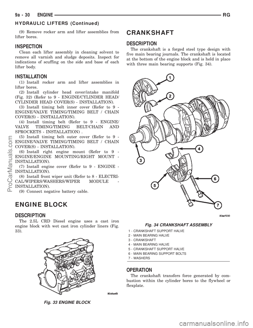
engine block with wet cast iron cylinder liners (Fig.
33).
CRANKSHAFT
DESCRIPTION
The crankshaft is a forged steel type design with
five main bearing journals. The crankshaft is located
at the bottom of the engine block and is held in place
with three main bearing supports (Fig. 34).
OPERATION
The crankshaft transfers force generated by com-
bustion within the cylinder bores to the flywheel or
flexplate.
Fig. 33 ENGINE BLOCK
Fig. 34 CRANKSHAFT ASSEMBLY
1 - CRANKSHAFT SUPPORT HALVE
2 - MAIN BEARING HALVE
3 - CRANKSHAFT
4 - MAIN BEARING HALVE
5 - CRANKSHAFT SUPPORT HALVE
6 - MAIN BEARING SUPPORT BOLTS
7 - WASHERS
9a - 30 ENGINERG
HYDRAULIC LIFTERS (Continued)
ProCarManuals.com
Page 1392 of 2399
STANDARD PROCEDURE - CHECKING
CRANKSHAFT END PLAY
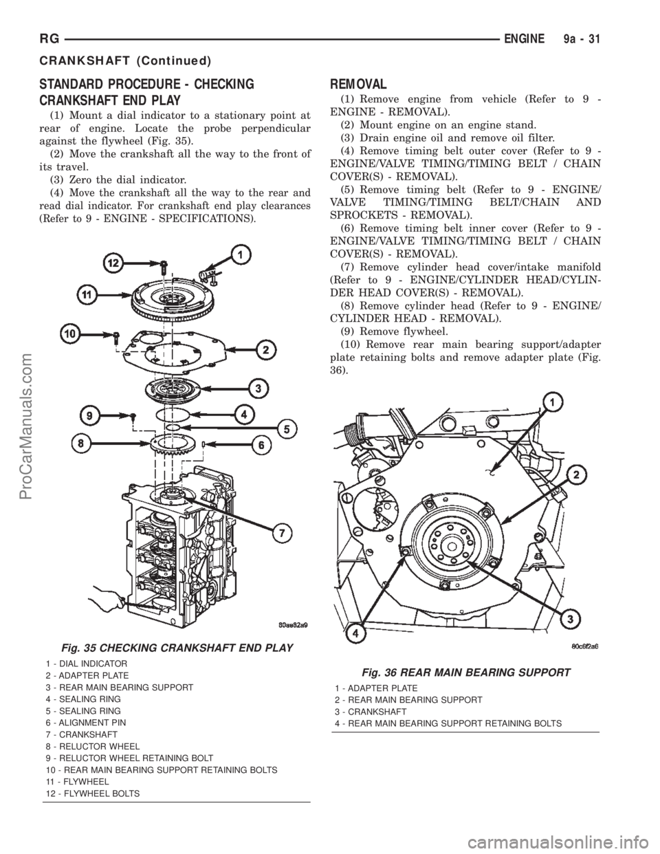
(1) Mount a dial indicator to a stationary point at
rear of engine. Locate the probe perpendicular
against the flywheel (Fig. 35).
(2) Move the crankshaft all the way to the front of
its travel.
(3) Zero the dial indicator.
(4)
Move the crankshaft all the way to the rear and
read dial indicator. For crankshaft end play clearances
(Refer to 9 - ENGINE - SPECIFICATIONS).
REMOVAL
(1) Remove engine from vehicle (Refer to 9 -
ENGINE - REMOVAL).
(2) Mount engine on an engine stand.
(3) Drain engine oil and remove oil filter.
(4) Remove timing belt outer cover (Refer to 9 -
ENGINE/VALVE TIMING/TIMING BELT / CHAIN
COVER(S) - REMOVAL).
(5) Remove timing belt (Refer to 9 - ENGINE/
VALVE TIMING/TIMING BELT/CHAIN AND
SPROCKETS - REMOVAL).
(6) Remove timing belt inner cover (Refer to 9 -
ENGINE/VALVE TIMING/TIMING BELT / CHAIN
COVER(S) - REMOVAL).
(7) Remove cylinder head cover/intake manifold
(Refer to 9 - ENGINE/CYLINDER HEAD/CYLIN-
DER HEAD COVER(S) - REMOVAL).
(8) Remove cylinder head (Refer to 9 - ENGINE/
CYLINDER HEAD - REMOVAL).
(9) Remove flywheel.
(10) Remove rear main bearing support/adapter
plate retaining bolts and remove adapter plate (Fig.
36).
Fig. 35 CHECKING CRANKSHAFT END PLAY
1 - DIAL INDICATOR
2 - ADAPTER PLATE
3 - REAR MAIN BEARING SUPPORT
4 - SEALING RING
5 - SEALING RING
6 - ALIGNMENT PIN
7 - CRANKSHAFT
8 - RELUCTOR WHEEL
9 - RELUCTOR WHEEL RETAINING BOLT
10 - REAR MAIN BEARING SUPPORT RETAINING BOLTS
11 - FLYWHEEL
12 - FLYWHEEL BOLTSFig. 36 REAR MAIN BEARING SUPPORT
1 - ADAPTER PLATE
2 - REAR MAIN BEARING SUPPORT
3 - CRANKSHAFT
4 - REAR MAIN BEARING SUPPORT RETAINING BOLTS
RGENGINE9a-31
CRANKSHAFT (Continued)
ProCarManuals.com
Page 1395 of 2399
INSPECTION
The cylinder walls should be checked for out-of-
round and taper with a dial bore gauge. The cylinder
bore out-of-round is 0.100 mm (.0039 in.) maximum
and cylinder bore taper is 0.100 mm (.0039 in.) max-
imum. If the cylinder walls are badly scuffed or
scored, new liners should be installed and honed, and
new pistons and rings fitted.
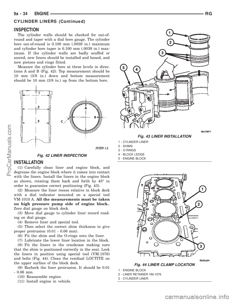
Measure the cylinder bore at three levels in direc-
tions A and B (Fig. 42). Top measurement should be
10 mm (3/8 in.) down and bottom measurement
should be 10 mm (3/8 in.) up from the bottom bore.
INSTALLATION
(1) Carefully clean liner and engine block, and
degrease the engine block where it comes into contact
with the liners. Install the liners in the engine block
as shown, rotating them back and forth by 45É in
order to guarantee correct positioning (Fig. 43).
(2) Measure the liner recess relative to block deck
with a dial indicator mounted on a special tool
VM-1010 A.All the measurements must be taken
on high pressure pump side of engine block..
Zero dial gauge on block deck.
(3) Move dial gauge to cylinder liner record read-
ing on dial gauge.
(4) Remove liner and special tool.
(5) Then select the correct shim thickness to give
proper protrusion (0.01 - 0.06 mm).
(6) Fit the shim and the O-rings onto the liner.
(7) Lubricate the lower liner location in the block.
(8) Fit the liners in the crankcase making sure
that the shim is positioned correctly in the seat. Lock
the liners in position using special tool (VM.1076)
and bolts (Fig. 44). Clean the residual LOCTITE on
the upper surface of the block deck.
(9) Recheck the liner protrusion. It should be 0.01
- 0.06 mm.
(10) Reassemble engine.
(11) Install engine in vehicle.
Fig. 42 LINER INSPECTION
Fig. 43 LINER INSTALLATION
1 - CYLINDER LINER
2 - SHIMS
3 - O-RINGS
4 - BLOCK LEDGE
5 - ENGINE BLOCK
Fig. 44 LINER CLAMP LOCATION
1 - ENGINE BLOCK
2 - LINER RETAINER VM.1076
3 - CYLINDER LINER
9a - 34 ENGINERG
CYLINDER LINERS (Continued)
ProCarManuals.com
Page 1396 of 2399
INTERNAL VACUUM PUMP
DESCRIPTION
The diesel engine uses a internal vacuum pump.
This vacuum pump is mounted in the front of the
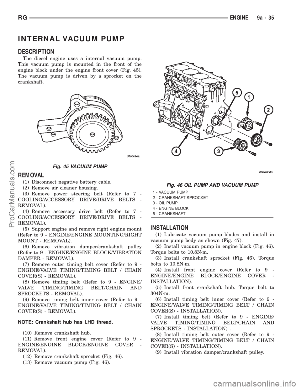
engine block under the engine front cover (Fig. 45).
The vacuum pump is driven by a sprocket on the
crankshaft.
REMOVAL
(1) Disconnect negative battery cable.
(2) Remove air cleaner housing.
(3) Remove power steering belt (Refer to 7 -
COOLING/ACCESSORY DRIVE/DRIVE BELTS -
REMOVAL).
(4) Remove accessory drive belt (Refer to 7 -
COOLING/ACCESSORY DRIVE/DRIVE BELTS -
REMOVAL).
(5) Support engine and remove right engine mount
(Refer to 9 - ENGINE/ENGINE MOUNTING/RIGHT
MOUNT - REMOVAL).
(6) Remove vibration damper/crankshaft pulley
(Refer to 9 - ENGINE/ENGINE BLOCK/VIBRATION
DAMPER - REMOVAL).
(7) Remove outer timing belt cover (Refer to 9 -
ENGINE/VALVE TIMING/TIMING BELT / CHAIN
COVER(S) - REMOVAL).
(8) Remove timing belt (Refer to 9 - ENGINE/
VALVE TIMING/TIMING BELT/CHAIN AND
SPROCKETS - REMOVAL).
(9) Remove timing belt inner cover (Refer to 9 -
ENGINE/VALVE TIMING/TIMING BELT / CHAIN
COVER(S) - REMOVAL).
NOTE: Crankshaft hub has LHD thread.
(10) Remove crankshaft hub.
(11) Remove front engine cover (Refer to 9 -
ENGINE/ENGINE BLOCK/ENGINE COVER -
REMOVAL).
(12) Remove crankshaft sprocket (Fig. 46).
(13) Remove vacuum pump (Fig. 46).
INSTALLATION
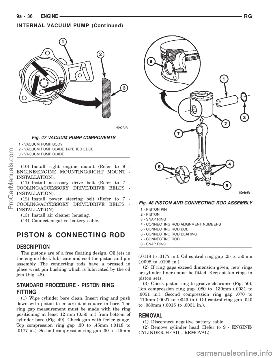
(1) Lubricate vacuum pump blades and install in
vacuum pump body as shown (Fig. 47).
(2) Install vacuum pump in engine block (Fig. 46).
Torque bolts to 10.8N´m.
(3) Install crankshaft sprocket (Fig. 46). Torque
bolts to 10.8N´m.
(4) Install front engine cover (Refer to 9 -
ENGINE/ENGINE BLOCK/ENGINE COVER -
INSTALLATION).
(5) Install front crankshaft hub. Torque bolt to
304N´m.
(6) Install timing belt inner cover (Refer to 9 -
ENGINE/VALVE TIMING/TIMING BELT / CHAIN
COVER(S) - INSTALLATION).
(7) Install timing belt (Refer to 9 - ENGINE/
VALVE TIMING/TIMING BELT/CHAIN AND
SPROCKETS - INSTALLATION) .
(8) Install timing belt outer cover (Refer to 9 -
ENGINE/VALVE TIMING/TIMING BELT / CHAIN
COVER(S) - INSTALLATION).
(9) Install vibration damper/crankshaft pulley.
Fig. 45 VACUUM PUMP
Fig. 46 OIL PUMP AND VACUUM PUMP
1 - VACUUM PUMP
2 - CRANKSHAFT SPROCKET
3 - OIL PUMP
4 - ENGINE BLOCK
5 - CRANKSHAFT
RGENGINE9a-35
ProCarManuals.com
Page 1397 of 2399
(10) Install right engine mount (Refer to 9 -
ENGINE/ENGINE MOUNTING/RIGHT MOUNT -
INSTALLATION).
(11) Install accessory drive belt (Refer to 7 -
COOLING/ACCESSORY DRIVE/DRIVE BELTS -
INSTALLATION).
(12) Install power steering belt (Refer to 7 -
COOLING/ACCESSORY DRIVE/DRIVE BELTS -
INSTALLATION).
(13) Install air cleaner housing.
(14) Connect negative battery cable.
PISTON & CONNECTING ROD
DESCRIPTION
The pistons are of a free floating design. Oil jets in
the engine block lubricate and cool the piston and pin
assembly. The connecting rods have a pressed in
place wrist pin bushing which is lubricated by the oil
jets (Fig. 48).
STANDARD PROCEDURE - PISTON RING
FITTING
(1) Wipe cylinder bore clean. Insert ring and push
down with piston to ensure it is square in bore. The
ring gap measurement must be made with the ring
positioning at least 12 mm (0.50 in.) from bottom of
cylinder bore (Fig. 49). Check gap with feeler gauge.
Top compression ring gap .30 to .45mm (.0118 to
.0177 in.). Second compression ring gap .30 to .45mm(.0118 to .0177 in.). Oil control ring gap .25 to .50mm
(.0098 to .0196 in.).
(2) If ring gaps exceed dimension given, new rings
or cylinder liners must be fitted. Keep piston rings in
piston sets.
(3) Check piston ring to groove clearance (Fig. 50).
Top compression ring gap .080 to .130mm (.0031 to
.0051 in.). Second compression ring gap .070 to
.110mm (.0027 to .0043 in.). Oil control ring gap .040
to .080mm (.0015 to .0031 in.).
REMOVAL
(1) Disconnect negative battery cable.
(2) Remove cylinder head (Refer to 9 - ENGINE/
CYLINDER HEAD - REMOVAL).
Fig. 47 VACUUM PUMP COMPONENTS
1 - VACUUM PUMP BODY
2 - VACUUM PUMP BLADE TAPERED EDGE
3 - VACUUM PUMP BLADE
Fig. 48 PISTON AND CONNECTING ROD ASSEMBLY
1 - PISTON PIN
2 - PISTON
3 - SNAP RING
4 - CONNECTING ROD ALIGNMENT NUMBERS
5 - CONNECTING ROD BOLT
6 - CONNECTING ROD BEARING
7 - CONNECTING ROD
8 - SNAP RING
9a - 36 ENGINERG
INTERNAL VACUUM PUMP (Continued)
ProCarManuals.com
Page 1402 of 2399
CRANKSHAFT OIL SEAL -
FRONT
REMOVAL
(1) Disconnect negative battery cable.
(2) Remove air cleaner housing.
(3) Support engine and remove right engine mount
(Refer to 9 - ENGINE/ENGINE MOUNTING/RIGHT
MOUNT - REMOVAL).
(4) Remove power steering belt (Refer to 7 -
COOLING/ACCESSORY DRIVE/DRIVE BELTS -
REMOVAL).
(5) Remove accessory drive belt (Refer to 7 -
COOLING/ACCESSORY DRIVE/DRIVE BELTS -
REMOVAL).
(6) Remove vibration damper/crankshaft pulley
(Refer to 9 - ENGINE/ENGINE BLOCK/VIBRATION
DAMPER - REMOVAL).
(7) Remove outer timing belt cover (Refer to 9 -
ENGINE/VALVE TIMING/TIMING BELT / CHAIN
COVER(S) - REMOVAL).
(8) Remove timing belt (Refer to 9 - ENGINE/
VALVE TIMING/TIMING BELT/CHAIN AND
SPROCKETS - REMOVAL).
(9) Remove timing belt inner cover (Refer to 9 -
ENGINE/VALVE TIMING/TIMING BELT / CHAIN
COVER(S) - REMOVAL).
NOTE: Crankshaft hub retaining bolt has LHD
thread.
(10) Remove crankshaft hub.
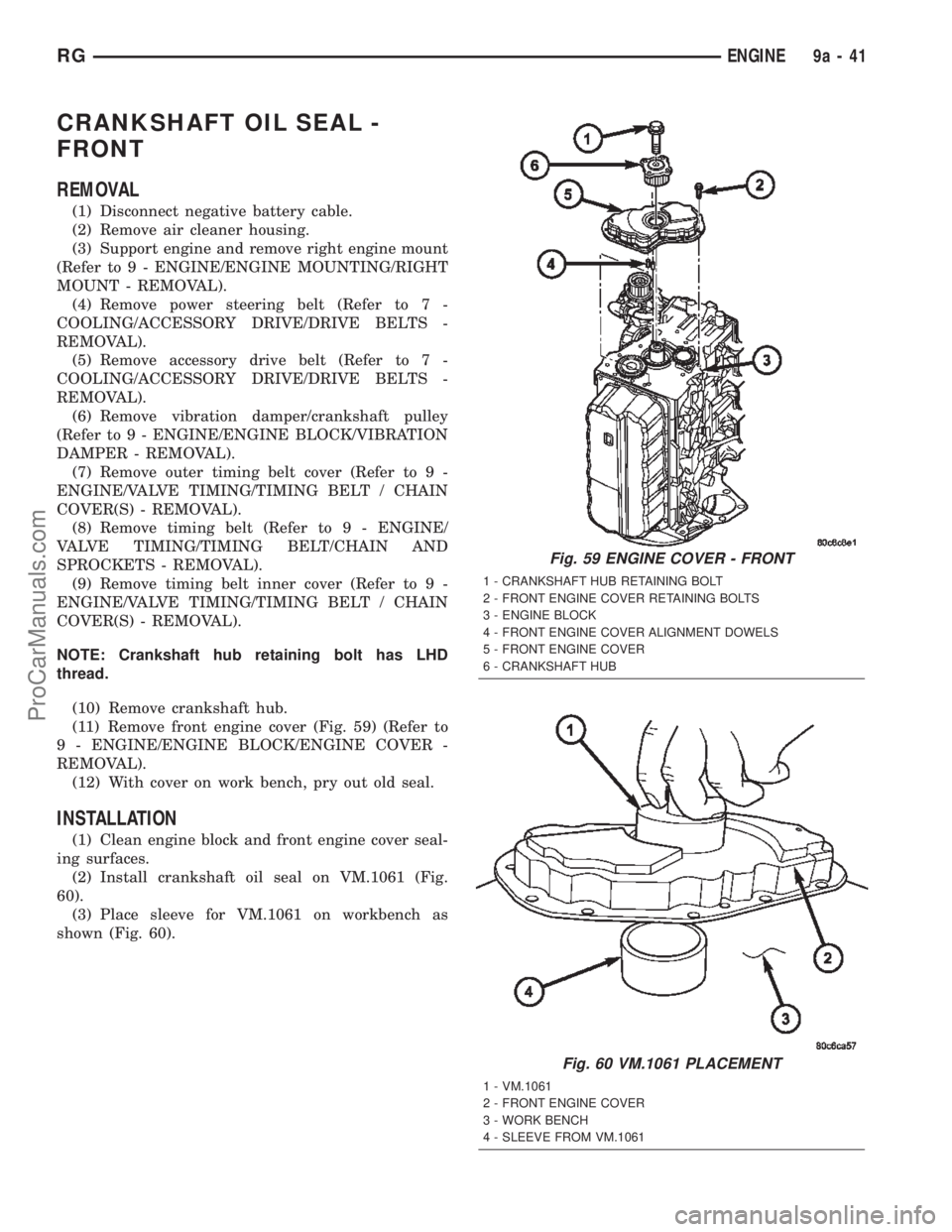
(11) Remove front engine cover (Fig. 59) (Refer to
9 - ENGINE/ENGINE BLOCK/ENGINE COVER -
REMOVAL).
(12) With cover on work bench, pry out old seal.
INSTALLATION
(1) Clean engine block and front engine cover seal-
ing surfaces.
(2) Install crankshaft oil seal on VM.1061 (Fig.
60).
(3) Place sleeve for VM.1061 on workbench as
shown (Fig. 60).
Fig. 59 ENGINE COVER - FRONT
1 - CRANKSHAFT HUB RETAINING BOLT
2 - FRONT ENGINE COVER RETAINING BOLTS
3 - ENGINE BLOCK
4 - FRONT ENGINE COVER ALIGNMENT DOWELS
5 - FRONT ENGINE COVER
6 - CRANKSHAFT HUB
Fig. 60 VM.1061 PLACEMENT
1 - VM.1061
2 - FRONT ENGINE COVER
3 - WORK BENCH
4 - SLEEVE FROM VM.1061
RGENGINE9a-41
ProCarManuals.com
Page 1403 of 2399
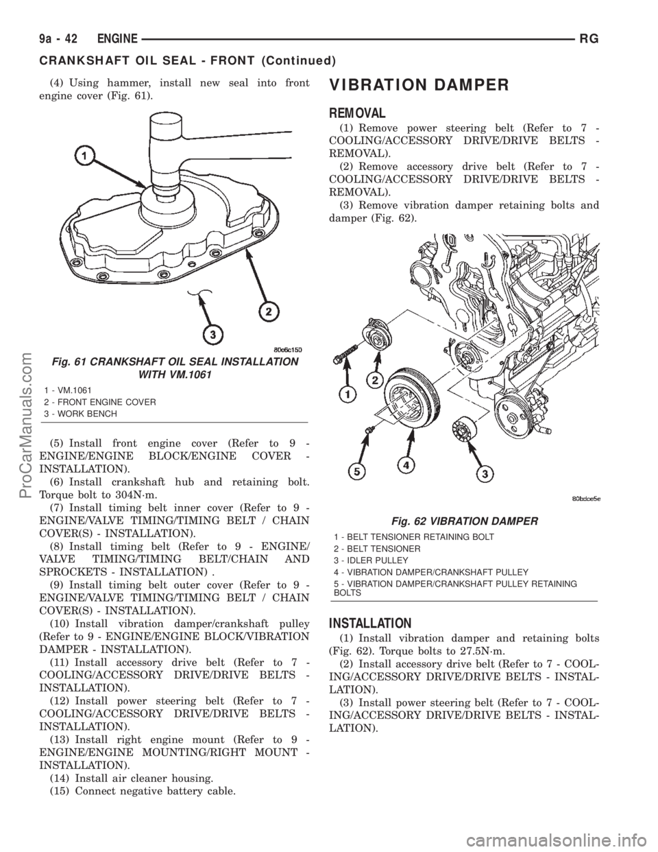
(4) Using hammer, install new seal into front
engine cover (Fig. 61).
(5) Install front engine cover (Refer to 9 -
ENGINE/ENGINE BLOCK/ENGINE COVER -
INSTALLATION).
(6) Install crankshaft hub and retaining bolt.
Torque bolt to 304N´m.
(7) Install timing belt inner cover (Refer to 9 -
ENGINE/VALVE TIMING/TIMING BELT / CHAIN
COVER(S) - INSTALLATION).
(8) Install timing belt (Refer to 9 - ENGINE/
VALVE TIMING/TIMING BELT/CHAIN AND
SPROCKETS - INSTALLATION) .
(9) Install timing belt outer cover (Refer to 9 -
ENGINE/VALVE TIMING/TIMING BELT / CHAIN
COVER(S) - INSTALLATION).
(10) Install vibration damper/crankshaft pulley
(Refer to 9 - ENGINE/ENGINE BLOCK/VIBRATION
DAMPER - INSTALLATION).
(11) Install accessory drive belt (Refer to 7 -
COOLING/ACCESSORY DRIVE/DRIVE BELTS -
INSTALLATION).
(12) Install power steering belt (Refer to 7 -
COOLING/ACCESSORY DRIVE/DRIVE BELTS -
INSTALLATION).
(13) Install right engine mount (Refer to 9 -
ENGINE/ENGINE MOUNTING/RIGHT MOUNT -
INSTALLATION).
(14) Install air cleaner housing.
(15) Connect negative battery cable.VIBRATION DAMPER
REMOVAL
(1) Remove power steering belt (Refer to 7 -
COOLING/ACCESSORY DRIVE/DRIVE BELTS -
REMOVAL).
(2) Remove accessory drive belt (Refer to 7 -
COOLING/ACCESSORY DRIVE/DRIVE BELTS -
REMOVAL).
(3) Remove vibration damper retaining bolts and
damper (Fig. 62).
INSTALLATION
(1) Install vibration damper and retaining bolts
(Fig. 62). Torque bolts to 27.5N´m.
(2) Install accessory drive belt (Refer to 7 - COOL-
ING/ACCESSORY DRIVE/DRIVE BELTS - INSTAL-
LATION).
(3) Install power steering belt (Refer to 7 - COOL-
ING/ACCESSORY DRIVE/DRIVE BELTS - INSTAL-
LATION).
Fig. 61 CRANKSHAFT OIL SEAL INSTALLATION
WITH VM.1061
1 - VM.1061
2 - FRONT ENGINE COVER
3 - WORK BENCH
Fig. 62 VIBRATION DAMPER
1 - BELT TENSIONER RETAINING BOLT
2 - BELT TENSIONER
3 - IDLER PULLEY
4 - VIBRATION DAMPER/CRANKSHAFT PULLEY
5 - VIBRATION DAMPER/CRANKSHAFT PULLEY RETAINING
BOLTS
9a - 42 ENGINERG
CRANKSHAFT OIL SEAL - FRONT (Continued)
ProCarManuals.com
Page 1404 of 2399
ENGINE COVER - FRONT
DESCRIPTION
The front engine cover on this engine is a stamped
steel cover which covers the oil pump and vacuum
pump.
REMOVAL
(1) Disconnect negative battery cable.
(2) Remove air cleaner housing.
(3) Support engine and remove right engine mount
(Refer to 9 - ENGINE/ENGINE MOUNTING/RIGHT
MOUNT - REMOVAL).
(4) Remove power steering belt (Refer to 7 -
COOLING/ACCESSORY DRIVE/DRIVE BELTS -
REMOVAL).
(5) Remove accessory drive belt (Refer to 7 -
COOLING/ACCESSORY DRIVE/DRIVE BELTS -
REMOVAL).
(6) Remove vibration damper (Refer to 9 -
ENGINE/ENGINE BLOCK/VIBRATION DAMPER -
REMOVAL).
(7) Remove timing belt outer cover (Refer to 9 -
ENGINE/VALVE TIMING/TIMING BELT / CHAIN
COVER(S) - REMOVAL).
CAUTION: Before removing the cylinder head cover/
intake manifold or timing belt the engine must put
at 90É after TDC. Failure to do so could result in
valve and/or piston damage during reassembly.
(Refer to 9 - ENGINE/VALVE TIMING - STANDARD
PROCEDURE)
(8) Remove timing belt (Refer to 9 - ENGINE/
VALVE TIMING/TIMING BELT/CHAIN AND
SPROCKETS - REMOVAL).
(9) Remove timing belt inner cover (Refer to 9 -
ENGINE/VALVE TIMING/TIMING BELT / CHAIN
COVER(S) - REMOVAL).
NOTE: Crankshaft hub has LHD thread.
(10) Remove crankshaft hub.
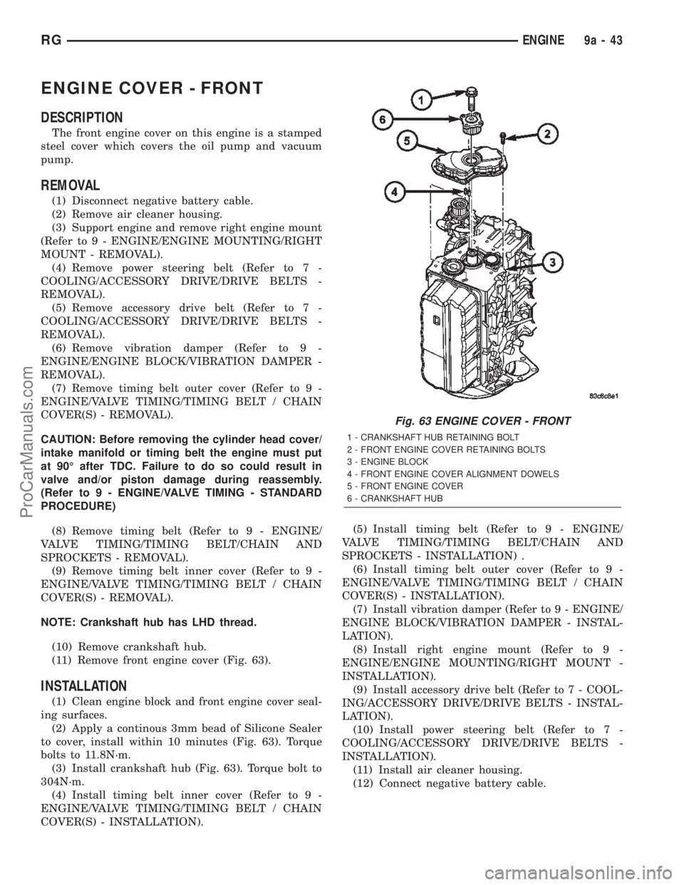
(11) Remove front engine cover (Fig. 63).
INSTALLATION
(1) Clean engine block and front engine cover seal-
ing surfaces.
(2) Apply a continous 3mm bead of Silicone Sealer
to cover, install within 10 minutes (Fig. 63). Torque
bolts to 11.8N´m.
(3) Install crankshaft hub (Fig. 63). Torque bolt to
304N´m.
(4) Install timing belt inner cover (Refer to 9 -
ENGINE/VALVE TIMING/TIMING BELT / CHAIN
COVER(S) - INSTALLATION).(5) Install timing belt (Refer to 9 - ENGINE/
VALVE TIMING/TIMING BELT/CHAIN AND
SPROCKETS - INSTALLATION) .
(6) Install timing belt outer cover (Refer to 9 -
ENGINE/VALVE TIMING/TIMING BELT / CHAIN
COVER(S) - INSTALLATION).
(7) Install vibration damper (Refer to 9 - ENGINE/
ENGINE BLOCK/VIBRATION DAMPER - INSTAL-
LATION).
(8) Install right engine mount (Refer to 9 -
ENGINE/ENGINE MOUNTING/RIGHT MOUNT -
INSTALLATION).
(9) Install accessory drive belt (Refer to 7 - COOL-
ING/ACCESSORY DRIVE/DRIVE BELTS - INSTAL-
LATION).
(10) Install power steering belt (Refer to 7 -
COOLING/ACCESSORY DRIVE/DRIVE BELTS -
INSTALLATION).
(11) Install air cleaner housing.
(12) Connect negative battery cable.
Fig. 63 ENGINE COVER - FRONT
1 - CRANKSHAFT HUB RETAINING BOLT
2 - FRONT ENGINE COVER RETAINING BOLTS
3 - ENGINE BLOCK
4 - FRONT ENGINE COVER ALIGNMENT DOWELS
5 - FRONT ENGINE COVER
6 - CRANKSHAFT HUB
RGENGINE9a-43
ProCarManuals.com
Page 1410 of 2399
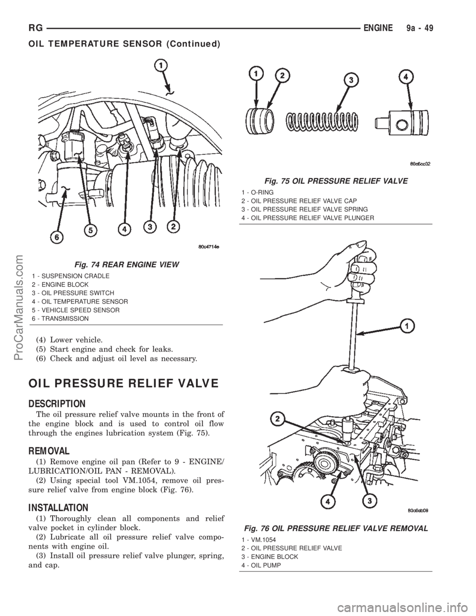
(4) Lower vehicle.
(5) Start engine and check for leaks.
(6) Check and adjust oil level as necessary.
OIL PRESSURE RELIEF VALVE
DESCRIPTION
The oil pressure relief valve mounts in the front of
the engine block and is used to control oil flow
through the engines lubrication system (Fig. 75).
REMOVAL
(1) Remove engine oil pan (Refer to 9 - ENGINE/
LUBRICATION/OIL PAN - REMOVAL).
(2) Using special tool VM.1054, remove oil pres-
sure relief valve from engine block (Fig. 76).
INSTALLATION
(1) Thoroughly clean all components and relief
valve pocket in cylinder block.
(2) Lubricate all oil pressure relief valve compo-
nents with engine oil.
(3) Install oil pressure relief valve plunger, spring,
and cap.
Fig. 74 REAR ENGINE VIEW
1 - SUSPENSION CRADLE
2 - ENGINE BLOCK
3 - OIL PRESSURE SWITCH
4 - OIL TEMPERATURE SENSOR
5 - VEHICLE SPEED SENSOR
6 - TRANSMISSION
Fig. 75 OIL PRESSURE RELIEF VALVE
1 - O-RING
2 - OIL PRESSURE RELIEF VALVE CAP
3 - OIL PRESSURE RELIEF VALVE SPRING
4 - OIL PRESSURE RELIEF VALVE PLUNGER
Fig. 76 OIL PRESSURE RELIEF VALVE REMOVAL
1 - VM.1054
2 - OIL PRESSURE RELIEF VALVE
3 - ENGINE BLOCK
4 - OIL PUMP
RGENGINE9a-49
OIL TEMPERATURE SENSOR (Continued)
ProCarManuals.com
Page 1415 of 2399
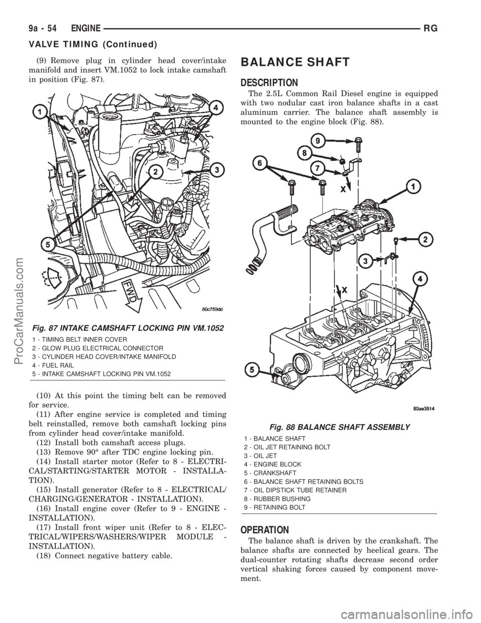
(9) Remove plug in cylinder head cover/intake
manifold and insert VM.1052 to lock intake camshaft
in position (Fig. 87).
(10) At this point the timing belt can be removed
for service.
(11) After engine service is completed and timing
belt reinstalled, remove both camshaft locking pins
from cylinder head cover/intake manifold.
(12) Install both camshaft access plugs.
(13) Remove 90É after TDC engine locking pin.
(14) Install starter motor (Refer to 8 - ELECTRI-
CAL/STARTING/STARTER MOTOR - INSTALLA-
TION).
(15) Install generator (Refer to 8 - ELECTRICAL/
CHARGING/GENERATOR - INSTALLATION).
(16) Install engine cover (Refer to 9 - ENGINE -
INSTALLATION).
(17) Install front wiper unit (Refer to 8 - ELEC-
TRICAL/WIPERS/WASHERS/WIPER MODULE -
INSTALLATION).
(18) Connect negative battery cable.BALANCE SHAFT
DESCRIPTION
The 2.5L Common Rail Diesel engine is equipped
with two nodular cast iron balance shafts in a cast
aluminum carrier. The balance shaft assembly is
mounted to the engine block (Fig. 88).
OPERATION
The balance shaft is driven by the crankshaft. The
balance shafts are connected by heelical gears. The
dual-counter rotating shafts decrease second order
vertical shaking forces caused by component move-
ment.
Fig. 87 INTAKE CAMSHAFT LOCKING PIN VM.1052
1 - TIMING BELT INNER COVER
2 - GLOW PLUG ELECTRICAL CONNECTOR
3 - CYLINDER HEAD COVER/INTAKE MANIFOLD
4 - FUEL RAIL
5 - INTAKE CAMSHAFT LOCKING PIN VM.1052
Fig. 88 BALANCE SHAFT ASSEMBLY
1 - BALANCE SHAFT
2 - OIL JET RETAINING BOLT
3 - OIL JET
4 - ENGINE BLOCK
5 - CRANKSHAFT
6 - BALANCE SHAFT RETAINING BOLTS
7 - OIL DIPSTICK TUBE RETAINER
8 - RUBBER BUSHING
9 - RETAINING BOLT
9a - 54 ENGINERG
VALVE TIMING (Continued)
ProCarManuals.com