engine mount CHRYSLER CARAVAN 2002 Service Manual
[x] Cancel search | Manufacturer: CHRYSLER, Model Year: 2002, Model line: CARAVAN, Model: CHRYSLER CARAVAN 2002Pages: 2399, PDF Size: 57.96 MB
Page 1335 of 2399
LEFT MOUNT
REMOVAL
(1) Raise the vehicle on hoist.
(2) Remove the left front wheel.
(3) Remove the left mount through bolt access
cover.
(4) Support the transaxle with a suitable jack.
(5) Remove the engine front mount through bolt to
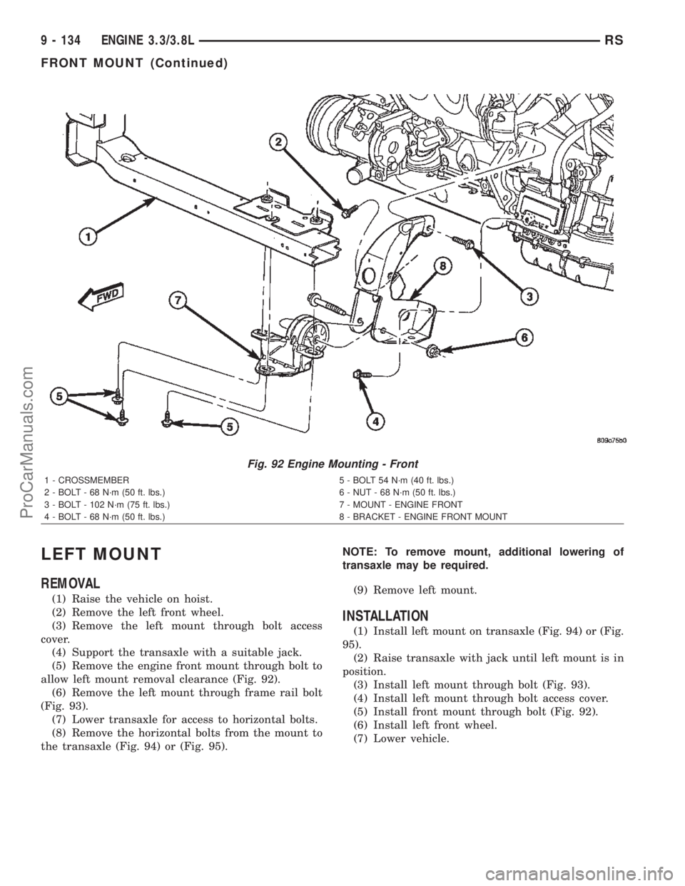
allow left mount removal clearance (Fig. 92).
(6) Remove the left mount through frame rail bolt
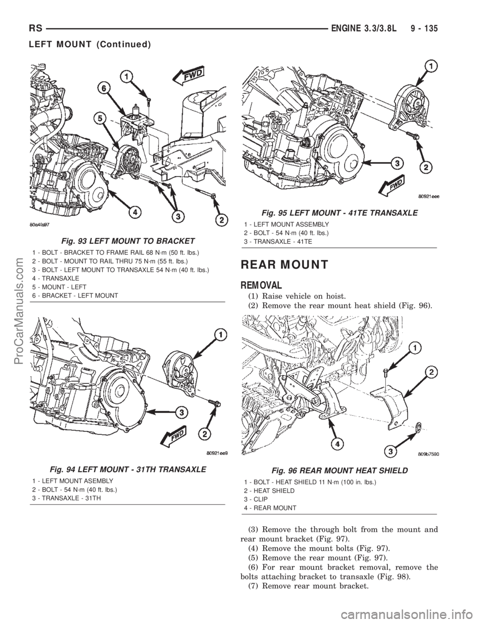
(Fig. 93).
(7) Lower transaxle for access to horizontal bolts.
(8) Remove the horizontal bolts from the mount to
the transaxle (Fig. 94) or (Fig. 95).NOTE: To remove mount, additional lowering of
transaxle may be required.
(9) Remove left mount.
INSTALLATION
(1) Install left mount on transaxle (Fig. 94) or (Fig.
95).
(2) Raise transaxle with jack until left mount is in
position.
(3) Install left mount through bolt (Fig. 93).
(4) Install left mount through bolt access cover.
(5) Install front mount through bolt (Fig. 92).
(6) Install left front wheel.
(7) Lower vehicle.
Fig. 92 Engine Mounting - Front
1 - CROSSMEMBER 5 - BOLT 54 N´m (40 ft. lbs.)
2 - BOLT - 68 N´m (50 ft. lbs.) 6 - NUT - 68 N´m (50 ft. lbs.)
3 - BOLT - 102 N´m (75 ft. lbs.) 7 - MOUNT - ENGINE FRONT
4 - BOLT - 68 N´m (50 ft. lbs.) 8 - BRACKET - ENGINE FRONT MOUNT
9 - 134 ENGINE 3.3/3.8LRS
FRONT MOUNT (Continued)
ProCarManuals.com
Page 1336 of 2399
REAR MOUNT
REMOVAL
(1) Raise vehicle on hoist.
(2) Remove the rear mount heat shield (Fig. 96).
(3) Remove the through bolt from the mount and
rear mount bracket (Fig. 97).
(4) Remove the mount bolts (Fig. 97).
(5) Remove the rear mount (Fig. 97).
(6) For rear mount bracket removal, remove the
bolts attaching bracket to transaxle (Fig. 98).
(7) Remove rear mount bracket.
Fig. 93 LEFT MOUNT TO BRACKET
1 - BOLT - BRACKET TO FRAME RAIL 68 N´m (50 ft. lbs.)
2 - BOLT - MOUNT TO RAIL THRU 75 N´m (55 ft. lbs.)
3 - BOLT - LEFT MOUNT TO TRANSAXLE 54 N´m (40 ft. lbs.)
4 - TRANSAXLE
5 - MOUNT - LEFT
6 - BRACKET - LEFT MOUNT
Fig. 94 LEFT MOUNT - 31TH TRANSAXLE
1 - LEFT MOUNT ASEMBLY
2 - BOLT - 54 N´m (40 ft. lbs.)
3 - TRANSAXLE - 31TH
Fig. 95 LEFT MOUNT - 41TE TRANSAXLE
1 - LEFT MOUNT ASSEMBLY
2 - BOLT - 54 N´m (40 ft. lbs.)
3 - TRANSAXLE - 41TE
Fig. 96 REAR MOUNT HEAT SHIELD
1 - BOLT - HEAT SHIELD 11 N´m (100 in. lbs.)
2 - HEAT SHIELD
3 - CLIP
4 - REAR MOUNT
RSENGINE 3.3/3.8L9 - 135
LEFT MOUNT (Continued)
ProCarManuals.com
Page 1337 of 2399
INSTALLATION
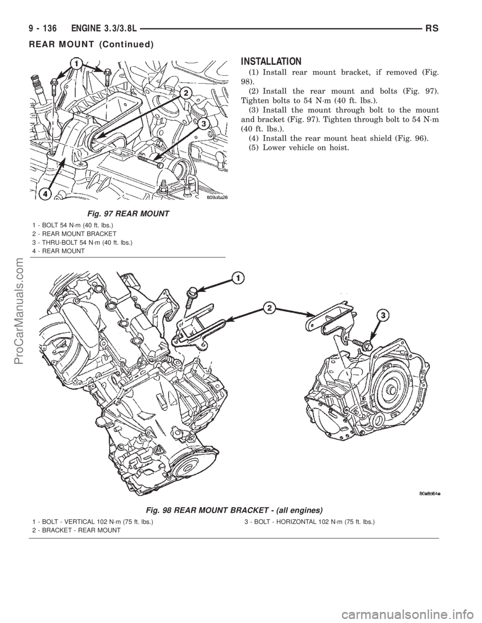
(1) Install rear mount bracket, if removed (Fig.
98).
(2) Install the rear mount and bolts (Fig. 97).
Tighten bolts to 54 N´m (40 ft. lbs.).
(3) Install the mount through bolt to the mount
and bracket (Fig. 97). Tighten through bolt to 54 N´m
(40 ft. lbs.).
(4) Install the rear mount heat shield (Fig. 96).
(5) Lower vehicle on hoist.
Fig. 97 REAR MOUNT
1 - BOLT 54 N´m (40 ft. lbs.)
2 - REAR MOUNT BRACKET
3 - THRU-BOLT 54 N´m (40 ft. lbs.)
4 - REAR MOUNT
Fig. 98 REAR MOUNT BRACKET - (all engines)
1 - BOLT - VERTICAL 102 N´m (75 ft. lbs.)
2 - BRACKET - REAR MOUNT3 - BOLT - HORIZONTAL 102 N´m (75 ft. lbs.)
9 - 136 ENGINE 3.3/3.8LRS
REAR MOUNT (Continued)
ProCarManuals.com
Page 1338 of 2399
RIGHT MOUNT
REMOVAL
(1) Remove air cleaner housing lid and clean air
hose from throttle body.
(2) Remove air cleaner element and housing.
(3) Disconnect make-up air hose from cylinder
head cover.
(4) Remove the load on the right engine mount by
carefully supporting the engine assembly with a floor
jack.
(5) Disconnect electrical harness support clips from
engine mount bracket.
(6) Remove the bolts attaching the engine mount
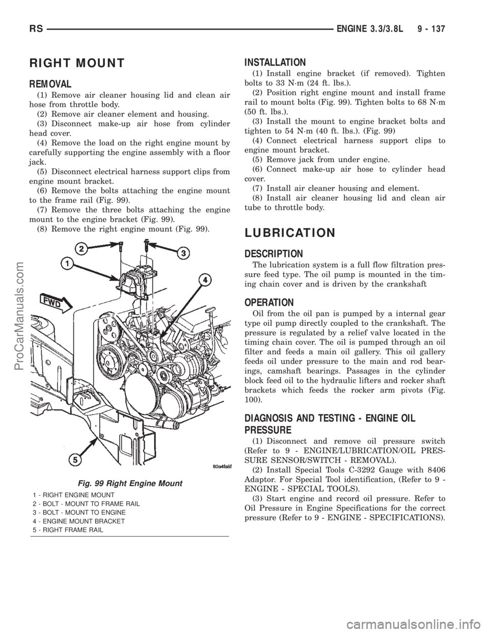
to the frame rail (Fig. 99).
(7) Remove the three bolts attaching the engine
mount to the engine bracket (Fig. 99).
(8) Remove the right engine mount (Fig. 99).
INSTALLATION
(1) Install engine bracket (if removed). Tighten
bolts to 33 N´m (24 ft. lbs.).
(2) Position right engine mount and install frame
rail to mount bolts (Fig. 99). Tighten bolts to 68 N´m
(50 ft. lbs.).
(3) Install the mount to engine bracket bolts and
tighten to 54 N´m (40 ft. lbs.). (Fig. 99)
(4) Connect electrical harness support clips to
engine mount bracket.
(5) Remove jack from under engine.
(6) Connect make-up air hose to cylinder head
cover.
(7) Install air cleaner housing and element.
(8) Install air cleaner housing lid and clean air
tube to throttle body.
LUBRICATION
DESCRIPTION
The lubrication system is a full flow filtration pres-
sure feed type. The oil pump is mounted in the tim-
ing chain cover and is driven by the crankshaft
OPERATION
Oil from the oil pan is pumped by a internal gear
type oil pump directly coupled to the crankshaft. The
pressure is regulated by a relief valve located in the
timing chain cover. The oil is pumped through an oil
filter and feeds a main oil gallery. This oil gallery
feeds oil under pressure to the main and rod bear-
ings, camshaft bearings. Passages in the cylinder
block feed oil to the hydraulic lifters and rocker shaft
brackets which feeds the rocker arm pivots (Fig.
100).
DIAGNOSIS AND TESTING - ENGINE OIL
PRESSURE
(1) Disconnect and remove oil pressure switch
(Refer to 9 - ENGINE/LUBRICATION/OIL PRES-
SURE SENSOR/SWITCH - REMOVAL).
(2) Install Special Tools C-3292 Gauge with 8406
Adaptor. For Special Tool identification, (Refer to 9 -
ENGINE - SPECIAL TOOLS).
(3) Start engine and record oil pressure. Refer to
Oil Pressure in Engine Specifications for the correct
pressure (Refer to 9 - ENGINE - SPECIFICATIONS).
Fig. 99 Right Engine Mount
1 - RIGHT ENGINE MOUNT
2 - BOLT - MOUNT TO FRAME RAIL
3 - BOLT - MOUNT TO ENGINE
4 - ENGINE MOUNT BRACKET
5 - RIGHT FRAME RAIL
RSENGINE 3.3/3.8L9 - 137
ProCarManuals.com
Page 1340 of 2399

(9) Lower vehicle and fill crankcase with specified
type and amount of engine oil. (Refer to LUBRICA-
TION & MAINTENANCE/FLUID TYPES -
DESCRIPTION)
(10) Install oil fill cap.
(11) Start engine and inspect for leaks.
(12) Stop engine and inspect oil level.
NOTE: Care should be exercised when disposing
used engine oil after it has been drained from a
vehicle engine. Refer to the WARNING listed above.
STANDARD PROCEDURE - ENGINE OIL LEVEL
CHECK
The best time to check engine oil level is after it
has sat overnight, or if the engine has been running,
allow the engine to be shut off for at least 5 minutes
before checking oil level.
Checking the oil while the vehicle is on level
ground will improve the accuracy of the oil level
reading (Fig. 102). Add only when the level is at or
below the ADD mark.
Fig. 102 Engine Oil Level Dipstick and Fill Locations
1 - COOLANT RECOVERY CONTAINER 3 - ENGINE OIL LEVEL DIPSTICK
2 - ENGINE OIL FILL CAP 4 - RADIATOR PRESSURE CAP
Fig. 101 Engine Oil Drain Plug and Oil Filter
1 - DRAIN PLUG
2 - OIL FILTER
RSENGINE 3.3/3.8L9 - 139
OIL (Continued)
ProCarManuals.com
Page 1341 of 2399

OIL COOLER & LINES
DESCRIPTION
An engine oil cooler is used on 3.3/3.8L engines
(Heavy Duty Cooling Only) (Fig. 104). The cooler is a
coolant-to-oil type and mounted between the oil filter
and engine block.
OPERATION
Engine oil travels from the oil filter and into the
oil cooler. Engine oil then exits the cooler into the
main gallery. Engine coolant flows into the cooler
from the heater return tube and exits into the water
pump inlet.
REMOVAL
(1) Drain cooling system (Refer to 7 - COOLING -
STANDARD PROCEDURE - COOLING SYSTEM
DRAINING).
(2) Disconnect oil cooler inlet and outlet hoses
(Fig. 103).
(3) Remove oil filter.
(4) Remove oil cooler attachment fitting (Fig. 104).
(5) Remove oil cooler.
INSTALLATION
(1) Lubricate seal and position oil cooler to connec-
tor fitting on oil filter adapter (Fig. 104).
NOTE: Position the flat side of oil cooler parallel to
oil pan rail.(2) Install oil cooler attachment fitting and tighten
to 27 N´m (20 ft. lbs.) (Fig. 104).
(3) Install oil filter.
(4) Connect oil cooler inlet and outlet hoses (Fig.
103).
(5) Fill cooling system (Refer to 7 - COOLING -
STANDARD PROCEDURE - COOLING SYSTEM
FILLING).
OIL FILTER
REMOVAL
CAUTION: When servicing the oil filter avoid
deforming the filter can by installing the remove/in-
stall tool band strap against the can-to-base lock
seam. The lock seam joining the can to the base is
reinforced by the base plate.
(1) Using suitable oil filter wrench, turn filter
counterclockwise to remove from oil filter adapter
(Fig. 105). Properly discard used oil filter.
INSTALLATION
(1) Wipe oil filter adapter base clean and inspect
gasket contact surface.
(2) Lubricate gasket of new filter with clean
engine oil.
(3) Install new filter until gasket contacts base
(Fig. 105). Tighten filter 1 turn or 20 N´m (15 ft.
lbs.). Use filter wrench if necessary.
(4) Start engine and check for leaks.
Fig. 103 Engine Oil Cooler Hoses
1 - OIL COOLER INLET TUBE
2 - INLET HOSE
3 - OIL COOLER OUTLET TUBE
4 - OUTLET HOSE
5 - WATER PUMP INLET TUBE
Fig. 104 Engine Oil Cooler - 3.3/3.8L (Heavy Duty
Cooling)
1 - OIL FILTER ADAPTER
2 - CONNECTOR
3 - ENGINE OIL COOLER
4 - OIL COOLER ATTACHMENT FITTING
5 - OIL FILTER
9 - 140 ENGINE 3.3/3.8LRS
ProCarManuals.com
Page 1342 of 2399
OIL FILTER ADAPTER
REMOVAL
(1) Raise vehicle on hoist.
(2) Remove the oil filter.
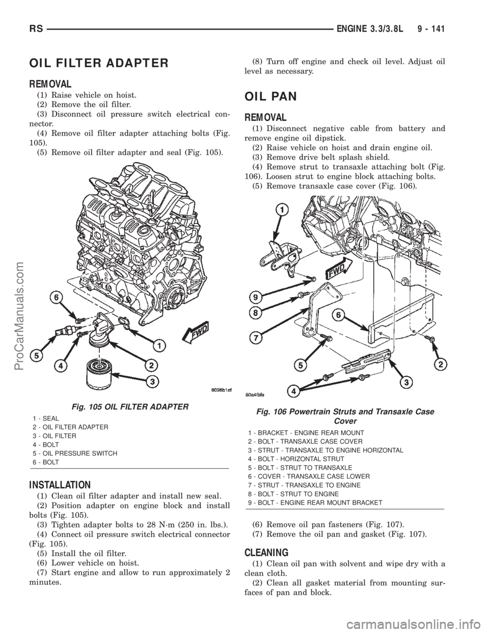
(3) Disconnect oil pressure switch electrical con-
nector.
(4) Remove oil filter adapter attaching bolts (Fig.
105).
(5) Remove oil filter adapter and seal (Fig. 105).
INSTALLATION
(1) Clean oil filter adapter and install new seal.
(2) Position adapter on engine block and install
bolts (Fig. 105).
(3) Tighten adapter bolts to 28 N´m (250 in. lbs.).
(4) Connect oil pressure switch electrical connector
(Fig. 105).
(5) Install the oil filter.
(6) Lower vehicle on hoist.
(7) Start engine and allow to run approximately 2
minutes.(8) Turn off engine and check oil level. Adjust oil
level as necessary.
OIL PAN
REMOVAL
(1) Disconnect negative cable from battery and
remove engine oil dipstick.
(2) Raise vehicle on hoist and drain engine oil.
(3) Remove drive belt splash shield.
(4) Remove strut to transaxle attaching bolt (Fig.
106). Loosen strut to engine block attaching bolts.
(5) Remove transaxle case cover (Fig. 106).
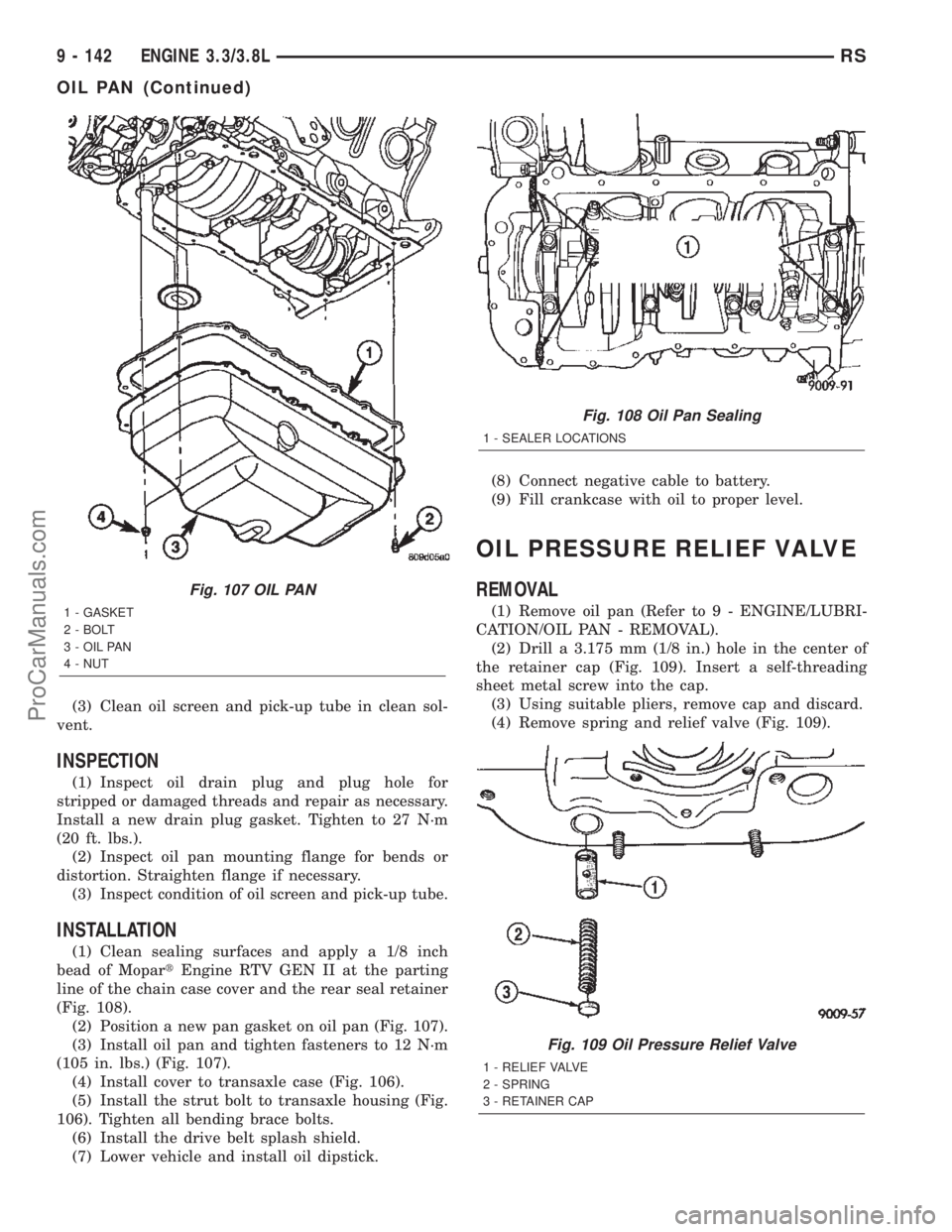
(6) Remove oil pan fasteners (Fig. 107).
(7) Remove the oil pan and gasket (Fig. 107).
CLEANING
(1) Clean oil pan with solvent and wipe dry with a
clean cloth.
(2) Clean all gasket material from mounting sur-
faces of pan and block.
Fig. 105 OIL FILTER ADAPTER
1 - SEAL
2 - OIL FILTER ADAPTER
3 - OIL FILTER
4 - BOLT
5 - OIL PRESSURE SWITCH
6 - BOLTFig. 106 Powertrain Struts and Transaxle Case
Cover
1 - BRACKET - ENGINE REAR MOUNT
2 - BOLT - TRANSAXLE CASE COVER
3 - STRUT - TRANSAXLE TO ENGINE HORIZONTAL
4 - BOLT - HORIZONTAL STRUT
5 - BOLT - STRUT TO TRANSAXLE
6 - COVER - TRANSAXLE CASE LOWER
7 - STRUT - TRANSAXLE TO ENGINE
8 - BOLT - STRUT TO ENGINE
9 - BOLT - ENGINE REAR MOUNT BRACKET
RSENGINE 3.3/3.8L9 - 141
ProCarManuals.com
Page 1343 of 2399
(3) Clean oil screen and pick-up tube in clean sol-
vent.
INSPECTION
(1) Inspect oil drain plug and plug hole for
stripped or damaged threads and repair as necessary.
Install a new drain plug gasket. Tighten to 27 N´m
(20 ft. lbs.).
(2) Inspect oil pan mounting flange for bends or
distortion. Straighten flange if necessary.
(3) Inspect condition of oil screen and pick-up tube.
INSTALLATION
(1) Clean sealing surfaces and apply a 1/8 inch
bead of MopartEngine RTV GEN II at the parting
line of the chain case cover and the rear seal retainer
(Fig. 108).
(2) Position a new pan gasket on oil pan (Fig. 107).
(3) Install oil pan and tighten fasteners to 12 N´m
(105 in. lbs.) (Fig. 107).
(4) Install cover to transaxle case (Fig. 106).
(5) Install the strut bolt to transaxle housing (Fig.
106). Tighten all bending brace bolts.
(6) Install the drive belt splash shield.
(7) Lower vehicle and install oil dipstick.(8) Connect negative cable to battery.
(9) Fill crankcase with oil to proper level.
OIL PRESSURE RELIEF VALVE
REMOVAL
(1) Remove oil pan (Refer to 9 - ENGINE/LUBRI-
CATION/OIL PAN - REMOVAL).
(2) Drill a 3.175 mm (1/8 in.) hole in the center of
the retainer cap (Fig. 109). Insert a self-threading
sheet metal screw into the cap.
(3) Using suitable pliers, remove cap and discard.
(4) Remove spring and relief valve (Fig. 109).
Fig. 107 OIL PAN
1 - GASKET
2 - BOLT
3 - OIL PAN
4 - NUT
Fig. 108 Oil Pan Sealing
1 - SEALER LOCATIONS
Fig. 109 Oil Pressure Relief Valve
1 - RELIEF VALVE
2 - SPRING
3 - RETAINER CAP
9 - 142 ENGINE 3.3/3.8LRS
OIL PAN (Continued)
ProCarManuals.com
Page 1349 of 2399

(7) Disconnect the manifold absolute pressure
(MAP) sensor electrical connector.
(8) Disconnect the vapor purge vacuum hose from
throttle body.
(9) Disconnect the PCV hose (Fig. 120).
(10) Remove the power steering reservoir attach-
ing bolts and only loosen the nut (Fig. 121). Lift res-
ervoir up to disengage lower mount from stud. Set
reservoir aside.Do notdisconnect hose.
(11) Disconnect the brake booster and leak detec-
tion pump (LDP) hoses from intake manifold (Fig.
122).
(12) Remove intake manifold bolts and remove the
manifold (Fig. 123).
(13) Cover the lower intake manifold with a suit-
able cover while the upper manifold is removed.
(14) Clean and inspect the upper intake manifold
(Refer to 9 - ENGINE/MANIFOLDS/INTAKE MANI-
FOLD - CLEANING) and (Refer to 9 - ENGINE/
MANIFOLDS/INTAKE MANIFOLD - INSPECTION).
CLEANING
(1) Discard gasket(s).
(2) Clean all sealing surfaces.
Fig. 120 PCV & HOSE
1 - HOSE - PCV
2 - P C V VA LV E
Fig. 121 POWER STEERING FLUID RESERVOIR
1 - POWER STEERING RESERVOIR
2 - BOLT - RESERVOIR TO MANIFOLD
3 - NUT - RESERVOIR TO COIL BRACKET
Fig. 122 BRAKE BOOSTER & LDP VACUUM HOSES
1 - LDP & SPEED CONTROL VACUUM HOSE
2 - BRAKE BOOSTER VACUUM HOSE
3 - MAP SENSOR
9 - 148 ENGINE 3.3/3.8LRS
INTAKE MANIFOLD - UPPER (Continued)
ProCarManuals.com
Page 1350 of 2399

INSPECTION
Check manifold for:
²Damage and cracks.
²Mounting surface distortion by using a straight-
edge and thickness gauge.
INSTALLATION - UPPER INTAKE MANIFOLD
(1) If the following components were removed from
manifold, install and tighten to specifications:
CAUTION: The special screws used for the compos-
ite manifold attached components must be installed
slowly using hand tools only. This requirement is to
prevent the melting of material that causes stripped
threads. If threads become stripped, an oversize
repair screw is available. For more information and
procedure (Refer to 9 - ENGINE/MANIFOLDS/IN-
TAKE MANIFOLD - STANDARD PROCEDURE - MAN-
IFOLD STRIPPED THREAD REPAIR).²MAP sensor - 1.7 N´m (15 in. lbs.)
²Throttle cable bracket - 5.6 N´m (50 in. lbs.)
(2) Remove covering on lower intake manifold and
clean surfaces.
(3) Inspect manifold gasket condition. Gaskets can
be re-used, if not damaged. To replace, remove gasket
from upper manifold (Fig. 123). Position new gasket
in seal channel and press lightly in-place. Repeat
procedure for each gasket position.
(4) Position upper manifold on lower manifold (Fig.
123). Install and tighten bolts to 12 N´m (105 in. lbs.)
following torque sequence in (Fig. 124).
(5) Connect the MAP sensor electrical connector.
(6) Connect the brake booster and LDP vacuum
hose to intake manifold (Fig. 122).
CAUTION: The special screws used for attaching
the EGR tube and power steering reservoir to the
manifold must be installed slowly using hand tools
only. This requirement is to prevent the melting of
material that causes stripped threads. If threads
become stripped, an oversize repair screw is avail-
able. For more information and procedure (Refer to
9 - ENGINE/MANIFOLDS/INTAKE MANIFOLD - STAN-
DARD PROCEDURE - MANIFOLD STRIPPED
THREAD REPAIR).
(7) Install the power steering reservoir (Fig. 121).
Tighten screws to manifold to 5.6 N´m (50 in. lbs.).
(8) Connect throttle and speed control cables to
throttle body (Refer to 14 - FUEL SYSTEM/FUEL
INJECTION/THROTTLE CONTROL CABLE -
INSTALLATION)
(9) Attach make up air hose clip into the hole in
the throttle cable bracket.
(10) Connect the wiring connectors to the throttle
position sensor (TPS) and Automatic Idle Speed (AIS)
motor.
Fig. 123 INTAKE MANIFOLD - UPPER
1 - BOLT
2 - MAP SENSOR
3 - SCREW
4 - MANIFOLD - UPPER
5 - WIRE HARNESS
6 - GASKET (3 PER CYL. BANK)
Fig. 124 UPPER MANIFOLD TIGHTENING
SEQUENCE
RSENGINE 3.3/3.8L9 - 149
INTAKE MANIFOLD - UPPER (Continued)
ProCarManuals.com