fig. 78 CHRYSLER CARAVAN 2002 Service Manual
[x] Cancel search | Manufacturer: CHRYSLER, Model Year: 2002, Model line: CARAVAN, Model: CHRYSLER CARAVAN 2002Pages: 2399, PDF Size: 57.96 MB
Page 289 of 2399
INSTALLATION
NOTE: When the transaxle cooler lines are removed
from the rolled-groove type fittings at the cooler
and transaxle, damage to the inner wall of hose will
occur. To prevent potential leakage, the cooler
hoses must be replaced.
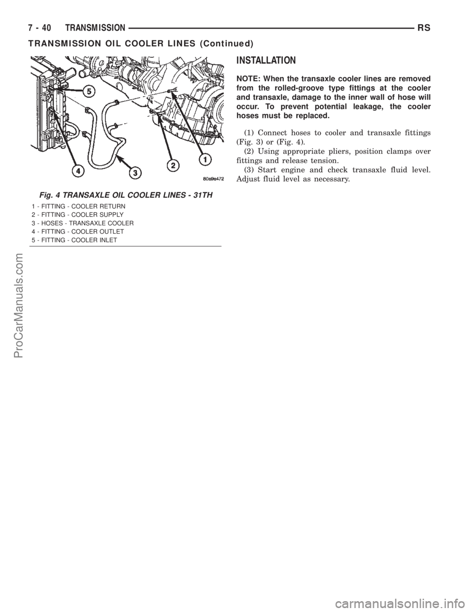
(1) Connect hoses to cooler and transaxle fittings
(Fig. 3) or (Fig. 4).
(2) Using appropriate pliers, position clamps over
fittings and release tension.
(3) Start engine and check transaxle fluid level.
Adjust fluid level as necessary.
Fig. 4 TRANSAXLE OIL COOLER LINES - 31TH
1 - FITTING - COOLER RETURN
2 - FITTING - COOLER SUPPLY
3 - HOSES - TRANSAXLE COOLER
4 - FITTING - COOLER OUTLET
5 - FITTING - COOLER INLET
7 - 40 TRANSMISSIONRS
TRANSMISSION OIL COOLER LINES (Continued)
ProCarManuals.com
Page 295 of 2399

CONDITION POSSIBLE CAUSES CORRECTION
4. Has undercoating been applied to
any unnecessary components?4. Clean undercoating as
necessary.
STEAM IS COMING FROM
FRONT OF VEHICLE
NEAR GRILL AREA WHEN
WEATHER IS WET,
ENGINE IS WARMED UP
AND RUNNING, AND
VEHICLE IS STATIONARY.
TEMPERATURE GAUGE
IS IN NORMAL RANGE1. During wet weather, moisture
(snow, ice, or rain condensation) on
the radiator will evaporate when the
thermostat opens. This opening
allows heated water into the radiator.
When the moisture contacts the hot
radiator, steam may be emitted. This
usually occurs in cold weather with
no fan or airflow to blow it away.1. Occasional steam emitting
from this area is normal. No
repair is necessary.
COOLANT ODOR 1. Coolant color is not necessarily an
indication of adequate corrosion or
temperature protection. Do not rely
on coolant color for determining
condition of coolant.1. Refer to Coolant in this group
for antifreeze tests. Adjust
antifreeze-to-water ratio as
necessary.
COOLANT LEVEL
CHANGES IN COOLANT
TANK. TEMPERATURE
GAUGE IS IN NORMAL
RANGE1. Level changes are to be expected
as coolant volume fluctuates with
engine temperature. If the level in
the tank was between the HOT and
COLD marks at normal engine
operating temperature, the level
should return to within that range
after operation at elevated
temperatures.1. This a normal condition. No
repair necessary.
DIAGNOSIS AND TESTING - COOLING SYSTEM
LEAK TEST
WARNING: THE WARNING WORDS ªDO NOT OPEN
HOTº ON THE RADIATOR PRESSURE CAP IS A
SAFETY PRECAUTION. WHEN HOT, PRESSURE
BUILDS UP IN COOLING SYSTEM. TO PREVENT
SCALDING OR INJURY, THE RADIATOR CAP
SHOULD NOT BE REMOVED WHILE THE SYSTEM
IS HOT OR UNDER PRESSURE.
With engine not running, remove pressure/vent cap
from the coolant recovery pressure container and
wipe the filler neck sealing seat clean. The coolant
recovery pressure container should be full.
Attach the Cooling System Tester 7700 or equiva-
lent to the radiator, as shown in (Fig. 1) and apply
104 kPa (15 psi) pressure. If the pressure drops more
than 13.8 kPa (2 psi) in 2 minutes, inspect all points
for external leaks.
All radiator and heater hoses should be shaken
while at 104 kPa (15 psi), since some leaks occur only
while driving due to engine movement.
If there are no external leaks, after the gauge dial
shows a drop in pressure, detach the tester. Startengine and run until the thermostat opens, allowing
the coolant to expand. Reattach the cooling system
tester. If the needle on the dial fluctuates it indicates
a combustion leak, usually a head gasket leak.
WARNING: WITH TOOL IN PLACE, PRESSURE WILL
BUILD UP FAST. EXCESSIVE PRESSURE BUILT UP,
BY CONTINUOUS ENGINE OPERATION, MUST BE
RELEASED TO A SAFE PRESSURE POINT. NEVER
PERMIT PRESSURE TO EXCEED 138 kPa (20 psi).
If the needle on the dial does not fluctuate, raise
the engine rpm a few times. If an abnormal amount
of coolant or steam emits from the tailpipe, it may
indicate a coolant leak caused by a faulty head gas-
ket, cracked engine block, or cracked cylinder head.
There may be internal leaks that can be deter-
mined by removing the oil dipstick. If water globules
appear intermixed with the oil it will indicate an
internal leak in the engine. If there is an internal
leak, the engine must be disassembled for repair.
7a - 6 COOLING 2.5L TURBO DIESELRG
COOLING 2.5L TURBO DIESEL (Continued)
ProCarManuals.com
Page 296 of 2399

DIAGNOSIS AND TESTING - COOLING SYSTEM
FLOW CHECK
To determine whether coolant is flowing through
the cooling system, use the following procedures:
(1) If engine is cold, idle engine until normal oper-
ating temperature is reached. Then feel the upper
radiator hose. If it is hot, coolant is circulating.
WARNING: DO NOT REMOVE THE COOLING SYS-
TEM PRESSURE CAP WITH THE SYSTEM HOT AND
UNDER PRESSURE BECAUSE SERIOUS BURNS
FROM COOLANT CAN OCCUR.(2) Remove pressure/vent cap when engine is cold,
idle engine until thermostat opens, you should
observe coolant flow while looking down in the cool-
ant recovery pressure container. Once flow is
detected install the pressure/vent cap.
DIAGNOSIS AND TESTING - COOLING SYSTEM
AERATION
Low coolant level in a cross flow radiator will
equalize in both tanks with engine off. With engine
at running and at operating temperature, the high
pressure inlet tank runs full and the low pressure
outlet tank drops, resulting in cooling system aera-
tion. Aeration will draw air into the water pump
resulting in the following:
²High reading shown on the temperature gauge.
²Loss of coolant flow through the heater core.
²Corrosion in the cooling system.
²Water pump seal may run dry, increasing the
risk of premature seal failure.
²Combustion gas leaks into the coolant can also
cause the above problems.
CLEANING
Drain cooling system and refill with clean water.
Refer to procedures in this section. Run engine with
pressure/vent cap installed until upper radiator hose
is hot. Stop engine and drain water from system. If
water is dirty; fill, run, and drain system again, until
water runs clear.
INSPECTION
After performing a cleaning/flush procedure,
inspect all hoses, clamps and connections for deterio-
ration and leaks. Inspect radiator and heater core for
leaks.
Fig. 1 PRESSURE TESTING COOLING SYSTEM
1 - COOLING SYSTEM PRESSURE TESTER
2 - COOLANT RECOVERY PRESSURE CONTAINER
RGCOOLING 2.5L TURBO DIESEL7a-7
COOLING 2.5L TURBO DIESEL (Continued)
ProCarManuals.com
Page 298 of 2399

ACCESSORY DRIVE
TABLE OF CONTENTS
page page
ACCESSORY DRIVE
SPECIFICATIONS - ACCESSORY BELT
TENSION.............................9
BELT TENSIONER
REMOVAL.............................9
INSTALLATION..........................9
IDLER PULLEY
REMOVAL.............................10
INSTALLATION.........................10
DRIVE BELTS
DESCRIPTION
DESCRIPTION - ACCESSORY DRIVE BELT . 10DESCRIPTION - POWER STEERING BELT . . 10
OPERATION
OPERATION-ACCESSORY DRIVE BELT....10
OPERATION-POWER STEERING BELT.....10
DIAGNOSIS AND TESTING - ACCESSORY
DRIVE BELT.........................11
REMOVAL
REMOVAL-ACCESSORY DRIVE BELT......11
REMOVAL...........................11
INSTALLATION
INSTALLATION-ACCESSORY DRIVE BELT . . 13
INSTALLATION-POWER STEERING BELT . . . 13
ACCESSORY DRIVE
SPECIFICATIONS - ACCESSORY BELT TENSION
ACCESSORY DRIVE
BELTGAUGE
2.5L DIESEL ENGINE
A/C Compressor/
GeneratorDynamic Tensioner
Power Steering Belt 300 N (67 lbs.)
BELT TENSIONER
REMOVAL
WARNING:: BECAUSE OF HIGH SPRING TENSION,
DO NOT ATTEMPT TO DISASSEMBLE THE AUTO-
MATIC BELT TENSIONER. THE TENSIONER IS SER-
VICED AS AN ASSEMBLY.
(1) Remove the power steering belt (Refer to 7 -
COOLING/ACCESSORY DRIVE/DRIVE BELTS -
REMOVAL).
(2) Remove the accessory drive belt (Refer to 7 -
COOLING/ACCESSORY DRIVE/DRIVE BELTS -
INSTALLATION).
(3) Remove the belt tensioner retaining bolt and
remove tensioner (Fig. 1).
INSTALLATION
(1) Install belt tensioner and retaining bolt (Fig.
1). Torque bolt to 47 N´m (35ft. lbs.).(2) Install the accessory drive belt (Refer to 7 -
COOLING/ACCESSORY DRIVE/DRIVE BELTS -
INSTALLATION).
(3) Install the power steering belt (Refer to 7 -
COOLING/ACCESSORY DRIVE/DRIVE BELTS -
INSTALLATION).
Fig. 1 BELT TENSIONER AND IDLER PULLEY
1 - BELT TENSIONER RETAINING BOLT
2 - BELT TENSIONER
3 - IDLER PULLEY
4 - VIBRATION DAMPER/CRANKSHAFT PULLEY
5 - VIBRATION DAMPER/CRANKSHAFT PULLEY RETAINING
BOLTS
RGACCESSORY DRIVE7a-9
ProCarManuals.com
Page 299 of 2399

IDLER PULLEY
REMOVAL
(1) Remove the accessory drive belt (Refer to 7 -
COOLING/ACCESSORY DRIVE/DRIVE BELTS -
REMOVAL).
CAUTION: IDLER PULLEY RETAINING BOLT HAS
LEFT HAND THREAD
(2) Remove the idler pulley (Fig. 2).
INSTALLATION
(1) Install the idler pulley (Fig. 2). Torque retain-
ing bolt to 22 N´m (16 ft. lbs.).
(2) Install the accessory drive belt (Refer to 7 -
COOLING/ACCESSORY DRIVE/DRIVE BELTS -
INSTALLATION).
(3) Install the power steering belt (Refer to 7 -
COOLING/ACCESSORY DRIVE/DRIVE BELTS -
INSTALLATION).
DRIVE BELTS
DESCRIPTION
DESCRIPTION - ACCESSORY DRIVE BELT
The accessory drive belt is a serpentine type belt
(Fig. 3). Satisfactory performance of these belts
depends on belt condition and proper belt tension.
DESCRIPTION - POWER STEERING BELT
The power steering belt is a serpentine type belt
(Fig. 3). Satisfactory performance of this belt depends
on condition of the belt.
OPERATION
OPERATION-ACCESSORY DRIVE BELT
The accessory drive belts form the link between
the engine crankshaft and the engine driven accesso-
ries.
OPERATION-POWER STEERING BELT
The power steering belt forms a link between the
engine crankshaft and the power steering pump.
Fig. 2 BELT TENSIONER AND IDLER PULLEY
1 - BELT TENSIONER RETAINING BOLT
2 - BELT TENSIONER
3 - IDLER PULLEY
4 - VIBRATION DAMPER/CRANKSHAFT PULLEY
5 - VIBRATION DAMPER/CRANKSHAFT PULLEY RETAINING
BOLTS
Fig. 3 ACCESSORY DRIVE BELT ROUTING
1 - GENERATOR
2 - IDLER PULLEY
3 - A/C COMPRESSOR CLUTCH
4 - POWER STEERING PUMP PULLEY
5 - POWER STEERING BELT
6 - CRANKSHAFT DAMPER/PULLEY
7 - BELT TENSIONER
8 - ACCESSORY DRIVE BELT
7a - 10 ACCESSORY DRIVERG
ProCarManuals.com
Page 300 of 2399

DIAGNOSIS AND TESTING - ACCESSORY DRIVE BELT
CONDITION POSSIBLE CAUSES CORRECTIONS
INSUFFICIENT ACCESSORY
OUTPUT DUE TO BELT SLIPPAGE1. Belt too loose 1. (a) Replace belt (auto-tensioned
belts)
2. Faulty belt tensioner 2. Replace tensioner as necessary
3. Belt excessively glazed or worn 3. Replace belt
BELT SQUEAL WHEN
ACCELERATING ENGINE1. Belts too loose 1. Check and replace belt tensioner
if necessary
2. Belt glazed 2. Replace belt
BELT SQUEAK AT IDLE 1. Belts too loose 1. (a) Replace belt
2. Dirt or paint imbedded in belt 2. Replace belt
3. Non-uniform belt 3. Replace belt
4. Misaligned pulleys 4. Align accessories
5. Non-uniform groove or eccentric
pulley5. Replace pulley
BELT ROLLED OVER IN GROOVE
OR BELT JUMPS OFF1. Broken cord in belt 1. Replace belt
2. Belt too loose, or too tight 2. Replace belt
3. Misaligned pulleys 3. Align accessories
4. Non-uniform groove or eccentric
pulley4. Replace pulley
REMOVAL
REMOVAL-ACCESSORY DRIVE BELT
(1) Remove the power steering belt (Refer to 7 -
COOLING/ACCESSORY DRIVE/DRIVE BELTS -
REMOVAL).
(2) Relieve tension on belt tensioner using a suit-
able wrench (Fig. 4) and lock tensioner with a drift
punch (Fig. 5).
(3) Remove the accessory drive belt.
REMOVAL
(1) Raise vehicle on hoist.
(2) Remove right front fender inner splash shield.
(3) Install power steering belt remover tool on
crankshaft damper (Fig. 6).
(4) Rotate engine clockwise to remove belt (Fig. 7).
RGACCESSORY DRIVE7a-11
DRIVE BELTS (Continued)
ProCarManuals.com
Page 301 of 2399

Fig. 4 ACCESSORY DRIVE BELT REMOVAL
1 - BELT TENSIONER
2 - ACCESSORY DRIVE BELT
3 - IDLER PULLEY
4 - A/C COMPRESSOR CLUTCH
5 - CRANKSHAFT DAMPER/PULLEY
6 - WRENCH
Fig. 5 LOCKING/LOCKING BELT TENSIONER
Fig. 6 POWER STEERING BELT REMOVAL TOOL
1 - VIBRATION DAMPER
2 - POWER STEERING PULLEY
3 - POWER STEERING BELT
4 - POWER STEERING BELT REMOVER
Fig. 7 POWER STEERING BELT REMOVAL
1 - VIBRATION DAMPER
2 - POWER STEERING BELT
3 - POPWER STEERING BELT REMOVER
7a - 12 ACCESSORY DRIVERG
DRIVE BELTS (Continued)
ProCarManuals.com
Page 302 of 2399

INSTALLATION
INSTALLATION-ACCESSORY DRIVE BELT
(1) Install the accessory drive belt in proper popsi-
tion (Fig. 8).
(2) Unlock belt tensioner by removing punch and
apply tension to accessory drive belt (Fig. 9).
(3) Install the power steering belt (Refer to 7 -
COOLING/ACCESSORY DRIVE/DRIVE BELTS -
INSTALLATION).
INSTALLATION-POWER STEERING BELT
(1) Install power steering belt installation tool
(Fig. 10).
(2) Install power steering belt on crankshaft and
rotate crankshaft clockwise until belt is fully
installed on crankshaft (Fig. 10).
(3) Remove installation tool from crankshaft.
(4) Install right front fender inner splash shield.
(5) Lower vehicle from hoist.
Fig. 8 ACCESSORY DRIVE BELT ROUTING
1 - GENERATOR
2 - IDLER PULLEY
3 - A/C COMPRESSOR CLUTCH
4 - POWER STEERING PUMP PULLEY
5 - POWER STEERING BELT
6 - CRANKSHAFT DAMPER/PULLEY
7 - BELT TENSIONER
8 - ACCESSORY DRIVE BELT
Fig. 9 LOCKING/UNLOCKING BELT TENSIONER
Fig. 10 POWER STEERING BELT INSTALLATION
1 - POWER STEERING BELT
2 - HOLDING HOOK
3 - POWER STEERING PUMP PULLEY
4 - VIBRATION DAMPER
5 - POWER STEERING BELT INSTALLATION TOOL
RGACCESSORY DRIVE7a-13
DRIVE BELTS (Continued)
ProCarManuals.com
Page 305 of 2399

STANDARD PROCEDURE
STANDARD PROCEDURE - COOLANT SERVICE
For engine coolant recommended service schedule,
(Refer to LUBRICATION & MAINTENANCE/MAIN-
TENANCE SCHEDULES - DESCRIPTION).
STANDARD PROCEDURE - ADDING
ADDITIONAL COOLANT
The pressure/vent cap should not be removed
from the coolant recovery pressure container
when the engine is hot.When additional coolant is
needed to maintain this level, it should be added to
the coolant recovery pressure container (Fig. 1). Use
only 50/50 mix of ethylene glycol type antifreeze and
distilled water. For the recommeded antifreeze/cool-
ant type (Refer to LUBRICATION & MAINTE-
NANCE/FLUID TYPES - DESCRIPTION).
CAUTION: Do not use well water, or suspect water
supply in cooling system. A 50/50 ethylene glycol
and distilled water mix is recommended. For the
recommeded antifreeze/coolant type (Refer to
LUBRICATION & MAINTENANCE/FLUID TYPES -
DESCRIPTION).
STANDARD PROCEDURE - COOLANT LEVEL
CHECK
NOTE: Do not remove pressure/vent cap for routine
coolant level inspections.
The coolant reserve system provides a quick visual
method for determining the coolant level without
removing the pressure/vent cap.With the engine
cold and not running,simply observe the level of
the coolant in the coolant recovery pressure container
(Fig. 2). The coolant level should be between the MIN
and MAX marks.
STANDARD PROCEDURE - COOLING SYSTEM
FILLING
(1) Remove pressure vent cap from coolant recov-
ery pressure container.
(2) Loosen air bleed screw on the thermostat hous-
ing (Fig. 9).
(3) Slowly fill the cooling through the coolant
recovery pressure container until a steady stream of
coolant comes out of the air bleed.
(4) Tighten the air bleed screw.
Fig. 1 UNDERHOOD FLUID FILL LOCATIONS
1 - COOLANT PRESSURE/VENT CAP
2 - BRAKE MASTER CYLINDER
3 - INTELLIGENT POWER MODULE
4 - BATTERY
5 - COOLANT RECOVERY PRESSURE CONTAINER6 - OIL DIPSTICK
7 - WINDSHIELD SOLVENT RESEVOIR
8 - AIR FILTER HOUSING
9 - ENGINE OIL FILL CAP
7a - 16 ENGINERG
ProCarManuals.com
Page 306 of 2399

(5) Continue filling coolant recovery pressure con-
tainer until level reaches the full line.
(6) Without installing the pressure/vent cap, start
and run engine at idle for a couple minutes.
(7) Recheck coolant level and fill as necessary.
(8) Install pressure/vent cap and drive vehicle for
approx. 10 km to reach normal operating tempera-
tures.
(9) Allow vehicle to cool. Check and fill coolant as
needed.
STANDARD PROCEDURE - COOLING SYSTEM
DRAINING
WARNING: DO NOT REMOVE OR LOOSEN THE
COOLANT PRESSURE/VENT CAP, CYLINDER
BLOCK DRAIN PLUGS, OR THE DRAINCOCK WHEN
THE SYSTEM IS HOT AND UNDER PRESSURE
BECAUSE SERIOUS BURNS FROM THE COOLANT
CAN OCCUR.(1)Without removing pressure/vent cap and
with system not under pressure, open the drain-
cock. The draincock is located on the lower right side
of radiator (Fig. 3).
(2) After the coolant recovery pressure container is
empty, then remove coolant pressure/vent cap.
COOLANT RECOVERY PRESS
CONTAINER
DESCRIPTION
The coolant recovery pressure container is
mounted in the engine compartment next to the bat-
tery. The coolant recovery pressure container is made
of plastic (Fig. 4).
OPERATION
The coolant recovery pressure container works
with the pressure/vent cap to use thermal expansion
and contraction of the coolant to keep the coolant
free of trapped air. Provides a convenient and safe
method for checking coolant level and adjusting level
at atmospheric pressure without removing the pres-
sure/vent cap. It also provides some reserve coolant
to cover deaeration, evaporation, or boiling losses.
Fig. 2 COOLANT RECOVERY PRESSURE
CONTAINER LOCATION
1 - PRESSURE/VENT CAP
2 - BRAKE MASTER CYLINDER
3 - BATTERY
4 - BATTERY SHIELD
5 - COOLANT RECOVERY PRESSURE CONTAINER RETAING
CLIP
6 - ENGINE COVER
7 - COOLANT RECOVERY PRESSURE CONTAINER
Fig. 3 DRAINCOCK LOCATION
1 - RADIATOR
2 - DRAINCOCK
3 - LOWER RADIATOR SUPPORT
4 - ELECTRIC COOLING FAN
RGENGINE7a-17
COOLANT (Continued)
ProCarManuals.com