sensor CHRYSLER CARAVAN 2005 Manual Online
[x] Cancel search | Manufacturer: CHRYSLER, Model Year: 2005, Model line: CARAVAN, Model: CHRYSLER CARAVAN 2005Pages: 2339, PDF Size: 59.69 MB
Page 421 of 2339
STANDARD PROCEDURE
SETTING TRANSMITTER CODES
(1) Turn off the engine.
(2) Erase the codes by pressing the two outside
buttons. Release the buttons when the display con-
firms the operation (about 20 seconds).
(3) Choose one of the three buttons to train. Place
the hand-held transmitter within one inch of the uni-
versal transmitter and push the buttons on both
transmitters.
(4) Release both buttons. Your universal transmit-
ter is now ªtrainedº. To train the other buttons,
repeat Step 3 and Step 4. Be sure to keep your hand-
held transmitter in case you need to retrain the uni-
versal transmitter.
ERASING TRANSMITTER CODES
To erase the universal transmitter codes, simply
hold down the two outside buttons until the display
confirms the operation.
NOTE: Individual channels cannot be erased. Eras-
ing the transmitter codes will erase ALL pro-
grammed codes.
REMOVAL
(1) For the universal transmitter removal proce-
dure, (Refer to 8 - ELECTRICAL/OVERHEAD CON-
SOLE/COMPASS/MINI-TRIP COMPUTER -
REMOVAL.
AMBIENT TEMP SENSOR
DESCRIPTION
Ambient air temperature is monitored by the over-
head console through ambient temperature messages
received from the Powertrain Control Module (PCM)
over the Programmable Communications Interface
(PCI) data bus circuit. The PCM receives a hard
wired input from the ambient temperature sensor.
The ambient temperature sensor is a variable resis-
tor mounted to a bracket that is secured with a screw
to the right side of the headlamp mounting module
grille opening, behind the radiator grille and in front
of the engine compartment.
For additional information on the PCM, (Refer to 8
- ELECTRICAL/ELECTRONIC CONTROL MOD-
ULES/POWERTRAIN CONTROL MODULE -
DESCRIPTION).
OPERATION
The ambient temperature sensor is a variable
resistor that operates on a five-volt reference signal
sent by the Powertrain Control Module (PCM). The
resistance in the sensor changes as temperature
changes, changing the temperature sensor signal cir-
cuit voltage to the PCM. Based upon the resistance
in the sensor, the PCM senses a specific voltage on
the temperature sensor signal circuit, which it is pro-
grammed to correspond to a specific temperature.
The PCM then sends the proper ambient tempera-
ture messages to the Electronic Vehicle Information
Center (EVIC)/Compass Mini-Trip Computer (CMTC)
over the Programmable Communication Interface
(PCI) data bus.
The thermometer function is supported by the
ambient temperature sensor, a wiring circuit, the
PCM, the PCI data bus, and the Electronics module.
If any portion of the ambient temperature sensor cir-
cuit fails, the PCM will self-diagnose the circuit.
The ambient temperature sensor circuit can also be
diagnosed manually (Refer to 8 - ELECTRICAL/
OVERHEAD CONSOLE/AMBIENT TEMP SENSOR
- DIAGNOSIS AND TESTING - AMBIENT TEM-
PERATURE SENSOR CIRCUIT). If the temperature
sensor and circuit are confirmed to be OK, but the
temperature display is inoperative or incorrect,
(Refer to 8 - ELECTRICAL/OVERHEAD CONSOLE -
DIAGNOSIS AND TESTING) to determine the cause.
For complete circuit diagrams, refer to the appropri-
ate wiring information.
DIAGNOSIS AND TESTING
AMBIENT TEMPERATURE SENSOR
(1) Turn the ignition switch to the Off position.
Disconnect and isolate the battery negative cable.
Disconnect the ambient temperature sensor wire har-
ness connector.
(2) Measure the resistance of the ambient temper-
ature sensor. At room temperature (approx. 68ÉF),
the sensor resistance should be between 10-13 Kilo-
hms. The sensor resistance should be between these
two values at 68ÉF. If the resistance is out of range
replace the ambient temperature sensor.
AMBIENT TEMPERATURE SENSOR CIRCUIT
(1) Turn the ignition switch to the Off position.
Disconnect and isolate the battery negative cable.
Disconnect the ambient temperature sensor wire har-
ness connector and the Powertrain Control Module
(PCM) wire harness connector.
8M - 12 OVERHEAD CONSOLERS
UNIVERSAL TRANSMITTER (Continued)
Page 422 of 2339
(2) Connect a jumper wire between the two termi-
nals in the body half of the ambient temperature sen-
sor wire harness connector.
(3) Check for continuity between the sensor return
circuit and the ambient temperature sensor signal
circuit cavities of the PCM wire harness connector.
There should be continuity. If OK, go to Step 4. If not
OK, repair the open sensor return circuit or ambient
temperature sensor signal circuit to the ambient tem-
perature sensor as required.
(4) Remove the jumper wire from the body half of
the ambient temperature sensor wire harness con-
nector. Check for continuity between the sensor
return circuit cavity of the PCM wire harness connec-
tor and a good ground. There should be no continuity.
If OK, go to Step 5. If not OK, repair the shorted
sensor return circuit as required.
(5) Check for continuity between the ambient tem-
perature sensor signal circuit cavity of the PCM wire
harness connector and a good ground. There should
be no continuity. If OK, (Refer to 8 - ELECTRICAL/
OVERHEAD CONSOLE - DIAGNOSIS AND TEST-ING) to determine the cause. If not OK, repair the
shorted ambient temperature sensor signal circuit as
required.
REMOVAL
(1) Disconnect and isolate the battery negative
cable.
(2) From behind the front bumper fascia, remove
the screw holding the sensor to the radiator closure
panel.
(3) Disconnect the sensor electrical connector.
(4) Remove the sensor from vehicle.
INSTALLATION
(1) Position the sensor in the vehicle and connect
the sensor electrical connector.
(2) From behind the front bumper fascia, install
the sensor mounting screw.
(3) Connect the battery negative cable.
RSOVERHEAD CONSOLE8M-13
AMBIENT TEMP SENSOR (Continued)
Page 424 of 2339

POWER SYSTEMS
TABLE OF CONTENTS
page page
POWER LIFTGATE SYSTEM.................. 1
POWER LOCKS........................... 20
POWER MIRRORS........................ 26POWER SEAT SYSTEM..................... 31
POWER SLIDING DOOR SYSTEM............ 40
POWER WINDOWS........................ 61
POWER LIFTGATE SYSTEM
TABLE OF CONTENTS
page page
POWER LIFTGATE SYSTEM
DESCRIPTION..........................2
OPERATION............................2
DIAGNOSIS AND TESTING
POWER LIFTGATE SYSTEM..............3
STANDARD PROCEDURE
LIFTGATE ADJUSTMENT................8
POWER LIFTGATE LEARN CYCLE.........8
CHIME/THERMISTOR
DESCRIPTION..........................8
OPERATION............................8
REMOVAL.............................8
INSTALLATION..........................9
ENGAGE ACTUATOR
DESCRIPTION..........................9
OPERATION............................9
REMOVAL.............................9
INSTALLATION.........................10
EXTERIOR HANDLE SWITCH
DESCRIPTION.........................10
OPERATION...........................10
REMOVAL.............................10
INSTALLATION.........................10
FULL OPEN SWITCH
DESCRIPTION.........................11
OPERATION...........................11
REMOVAL.............................11
INSTALLATION.........................11
LATCH
DESCRIPTION.........................12OPERATION...........................12
REMOVAL.............................12
INSTALLATION.........................13
LATCH ACTUATOR
DESCRIPTION.........................13
OPERATION...........................13
REMOVAL.............................13
INSTALLATION.........................14
LIFTGATE MOTOR
DESCRIPTION.........................15
OPERATION...........................15
REMOVAL.............................15
INSTALLATION.........................16
LIFT GEAR & LINK ROD
DESCRIPTION.........................16
OPERATION...........................16
REMOVAL.............................16
INSTALLATION.........................17
PINCH SENSOR
DESCRIPTION.........................17
OPERATION...........................17
REMOVAL.............................18
INSTALLATION.........................18
TRANSVERSE BRACKET
DESCRIPTION.........................19
OPERATION...........................19
REMOVAL.............................19
INSTALLATION.........................19
RSPOWER SYSTEMS8N-1
Page 425 of 2339
POWER LIFTGATE SYSTEM
DESCRIPTION
the components of the power liftgate system are:
²Liftgate gear motor assembly
²Latch assembly
²Lift gear and rod
²Power liftgate control module
²Chime/thermistor
²Full open switch
²Engage actuator
²Pinch sensor
²Liftgate handle switch
²Overhead console switch
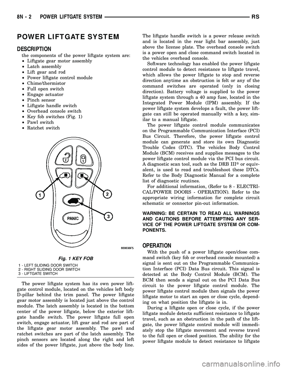
²Key fob switches (Fig. 1)
²Pawl switch
²Ratchet switch
The power liftgate system has its own power lift-
gate control module, located on the vehicles left body
D-pillar behind the trim panel. The power liftgate
gear motor assembly is located just above the control
module. The latch assembly is located in the bottom
center of the power liftgate, below the exterior lift-
gate handle switch. The power liftgate full open
switch, engage actuator, lift gear and rod are part of
the liftgate gear motor assembly. The pawl and
ratchet switches are part of the latch assembly. The
pinch sensors are located along the right and left
sides of the power liftgate, just above the body line.The liftgate handle switch is a power release switch
and is located in the rear light bar assembly, just
above the license plate. The overhead console switch
is a power open and close command switch located in
the vehicles overhead console.
Software technology has enabled the power liftgate
control module to detect resistance to liftgate travel,
which allows the power liftgate to stop and reverse
direction anytime an obstruction is felt or any of the
command switches are operated (only in closing
direction). Battery voltage is supplied to the power
liftgate system through a 40 amp fuse, located in the
Integrated Power Module (IPM) assembly. If the
power liftgate system develops a fault, the power lift-
gate can still be operated manually with a key, sim-
ilar to a manual liftgate.
The power liftgate control module communicates
on the Programmable Communication Interface (PCI)
Bus Circuit. Therefore, the power liftgate control
module can generate and store its own Diagnostic
Trouble Codes (DTC). The vehicles Body Control
Module (BCM) receives and supplies messages to the
power liftgate control module via the PCI bus circuit.
A diagnostic scan tool, such as the DRB IIItor equiv-
alent, is used to read and troubleshoot these DTCs.
Refer to the Body Diagnostic Manual for a complete
list of diagnostic routines.
For additional information, (Refer to 8 - ELECTRI-
CAL/POWER DOORS - OPERATION). Refer to the
appropriate wiring information for complete circuit
schematic or connector pin-out information.
WARNING: BE CERTAIN TO READ ALL WARNINGS
AND CAUTIONS BEFORE ATTEMPTING ANY SER-
VICE OF THE POWER LIFTGATE SYSTEM OR COM-
PONENTS.
OPERATION
With the push of a power liftgate open/close com-
mand switch (key fob or overhead console mounted) a
signal is sent out on the Programmable Communica-
tion Interface (PCI) Data Bus circuit. This signal is
detected at the Body Control Module (BCM). The
BCM then sends a signal out on the PCI Data Bus
circuit to the power liftgate control module. The
power liftgate control module then signals the power
liftgate motor to start an open or close cycle, depend-
ing on what position the liftgate is in.
During a liftgate open or close cycle, if the power
liftgate module detects sufficient resistance to liftgate
travel, such as an obstruction in the path of the lift-
gate, the power liftgate control module will immedi-
ately stop the liftgate movement and reverse travel
to the full open or closed position. The ability for the
power liftgate module to detect resistance to liftgate
Fig. 1 KEY FOB
1 - LEFT SLIDING DOOR SWITCH
2 - RIGHT SLIDING DOOR SWITCH
3 - LIFTGATE SWITCH
8N - 2 POWER LIFTGATE SYSTEMRS
Page 426 of 2339

travel is accomplished by hall effect sensors, drive
motor speed and pinch sensors (tape switches).
Anytime the liftgate is opened or closed using the
power liftgate system the power liftgate control mod-
ule learns from the cycle. If a replacement power lift-
gate component is installed or a liftgate adjustment
is made, the module will relearn the effort and/or
time required to open or close the liftgate. This learn
cycle can be performed with a DRB IIIt, or equiva-
lent scan tool, or with a complete cycle of the liftgate,
using any one of the command switches. (Refer to 8 -
ELECTRICAL/POWER DOORS - STANDARD PRO-
CEDURE) for detailed instructions.
The power liftgate system is designed with a num-
ber of system inhibitors. These inhibitors are neces-
sary for safety and / or feasibility of the power
liftgate system. The power liftgate system inhibitors
are:
²The Power Liftgate may not operate in extreme
temperatures. These extreme temperatures will be
approximately less than -12É F (-24.4É C) or greater
than 143É F (61.6É C). A chime/thermister assembly
in the rear light bar assembly monitors the outside
temperature.
²The vehicle transmission must be in Park or
Neutral for the power liftgate to start a cycle.
²If multiple obstacles are detected during the
same power open or close cycle, the liftgate goes into
manual operation.
²If severe problems occur, Diagnostic Trouble
Codes (DTC) are stored in the power liftgate control
module.
POWER LIFTGATE SYSTEM CAUTIONS AND
WARNINGS
WARNING: ALWAYS DISCONNECT THE BATTERY
NEGATIVE CABLE BEFORE ATTEMPTING ANY
POWER LIFTGATE SYSTEM SERVICE.
WARNING: THERE IS A SMALL AREA ON BOTH
SIDES OF THE LOWER POWER LIFTGATE WHICH
IS NOT PROTECTED BY PINCH SENSORS.
EXTREME CARE MUST BE TAKEN TO PREVENT
OBJECTS FROM ENTERING THIS AREA ONCE THELIFTGATE REACHES THE SECONDARY LATCH
CONTACT (APPROXIMATELY 1/2 INCH BEFORE
FULLY CLOSED).
WARNING: NEVER ATTEMPT TO ENTER OR EXIT
THE VEHICLE WITH THE LIFTGATE IN MOTION.
YOU COULD DAMAGE THE POWER LIFTGATE SYS-
TEM AND/OR COMPONENTS AND/OR CAUSE PER-
SONAL INJURY.
WARNING: NEVER STICK OBJECTS IN THE POWER
LIFTGATE WHEN CINCHING CLOSED. YOU COULD
DAMAGE THE VEHICLE, POWER LIFTGATE SYS-
TEM COMPONENTS AND/OR CAUSE PERSONAL
INJURY.
DIAGNOSIS AND TESTING
POWER LIFTGATE SYSTEM
The power liftgate system contains many compo-
nents and modules. In order to obtain conclusive
testing the Programmable Communications Interface
(PCI) data bus network and all of the electronic mod-
ules that provide inputs to, or receive outputs from
the power liftgate system must be checked.
The power liftgate system can be diagnosed with
an appropriate scan tool, such as the DRB IIItor
equivalent. The DRB IIItcan be used to observe var-
ious switch statuses throughout the power liftgate
system to help diagnose an inoperative switch or
component. The DRB IIItcan also be used to actuate
various components throughout the power liftgate
system to help diagnose an inoperative component.
Before any testing of the power liftgate system is
attempted, the battery should be fully charged, all
built-in power liftgate system inhibitors read and
understood, and all wire harness and ground connec-
tions inspected around the affected areas on the vehi-
cle.
The following are quick reference diagnostic tables
to help when diagnosing and testing the power lift-
gate system.
RSPOWER LIFTGATE SYSTEM8N-3
POWER LIFTGATE SYSTEM (Continued)
Page 431 of 2339

STANDARD PROCEDURE
LIFTGATE ADJUSTMENT
In order for the power liftgate system to function
properly the liftgate must move freely and smoothly.
The power liftgate system can accommodate for some
minor changes in the effort required to move the lift-
gate. However, in extreme conditions the liftgate may
need to be mechanically adjusted for proper fit and
finish. (Refer to 23 - BODY/DECKLID/HATCH/LIFT-
GATE/TAILGATE/LIFTGATE - INSTALLATION) for
detailed instructions.
If a problem exists with the power liftgate and it is
suspected to be extreme effort, check the liftgate prop
rods and hinges for free movement.
NOTE: Routine application of Mopar MP-50Tor
equivalent on the chrome prop rod shafts and lift-
gate latch and hinges will help keep the liftgate in
good working order.
POWER LIFTGATE LEARN CYCLE
Any time a power liftgate component is removed,
replaced or a liftgate adjustment is performed a learn
cycle must be performed. This learn cycle enables the
power liftgate control module to learn or relearn
information (travel limits, resistance to door travel,
etc.) which allows it to perform properly and safely.
Perform the following to complete a power liftgate
learn cycle:
(1) Obtain a DRBIIIt, or equivalent scan tool.
(2) Connect the scan tool to the vehicle and check
for any power liftgate system stored Diagnostic Trou-
ble Codes (DTCs), correct and erase any stored
DTCs.
(3) Using the scan tool, Go into Test Routine Menu
and select the power open command.
(4) Select the power close command.
(5) The liftgate learn cycle is complete.
If a DRBIIItor equivalent scan tool is not avail-
able, the learn cycle can be performed by actuating
the liftgate using any of the normal command
switches. Be certain to cycle the liftgate through a
complete open and close cycle before returning the
vehicle to service.
NOTE: If the power liftgate will not complete a full
cycle a problem exists with the power liftgate sys-
tem. (Refer to 8 - ELECTRICAL/POWER DOORS -
DIAGNOSIS AND TESTING).
CHIME/THERMISTOR
DESCRIPTION
The chime/thermistor assembly is a small capacitor
shaped electrical component mounted to the rear
license plate lamp housing assembly (Fig. 2) , located
just above the license plate. The chime portion of the
assembly controls the audible chime sound heard at
the rear of the vehicle when the power liftgate is in
motion. The thermistor portion of the assembly is a
temperature sensor, used by the power liftgate con-
trol module. The chime/thermistor assembly is a ser-
viceable component.
OPERATION
The chime/thermistor assembly performs two dif-
ferent functions for the power liftgate system. First,
the chime portion provides an audible chime sound
which is controlled by the power liftgate control mod-
ule. The chime/thermistor assembly is hardwired to
the power liftgate control module. Second the ther-
mistor provides a outside temperature reading by
way of a resistance reading supplied to the power
liftgate control module. As temperature increases the
resistance reading increases, as temperature
decreases the resistance reading decreases.
REMOVAL
(1) Disconnect and isolate the battery negative
cable.
Fig. 2 REAR LIGHT BAR
1 - CHIME / THERMISTOR
2 - ELECTRIC RELEASE HANDLE SWITCH
3 - LICENSE PLATE LAMPS
8N - 8 POWER LIFTGATE SYSTEMRS
POWER LIFTGATE SYSTEM (Continued)
Page 438 of 2339
LIFTGATE MOTOR
DESCRIPTION
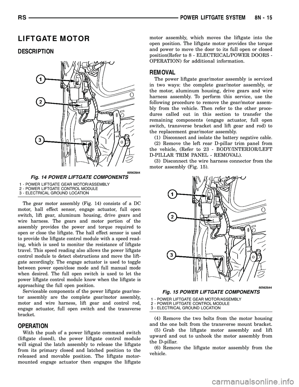
The gear motor assembly (Fig. 14) consists of a DC
motor, hall effect sensor, engage actuator, full open
switch, lift gear, aluminum housing, drive gears and
wire harness. The gears and motor portion of the
assembly provides the power and torque required to
open or close the liftgate. The hall effect sensor is used
to provide the liftgate control module with a speed read-
ing, which is used to monitor the resistance of liftgate
travel. This speed reading also allows the power liftgate
control module to detect obstructions and move the lift-
gate accordingly. The engage actuator is used to toggle
between power open/close mode and full manual mode
when desired. The full open switch is used to let the
power liftgate control module know when the liftgate is
approaching the full open position.
Serviceable components of the power liftgate gear/mo-
tor assembly are the complete gear/motor assembly,
motor and wire harness, lift gear and control rod,
engage actuator, full open switch and the transverse
bracket.
OPERATION
With the push of a power liftgate command switch
(liftgate closed), the power liftgate control module
will signal the latch assembly to release the liftgate
from its primary closed and latched position to the
released and movable position. The liftgate motor-
mounted engage actuator then engages the liftgatemotor assembly, which moves the liftgate into the
open position. The liftgate motor provides the torque
and power to move the door to its full open or closed
position(Refer to 8 - ELECTRICAL/POWER DOORS -
OPERATION) for additional information.
REMOVAL
The power liftgate gear/motor assembly is serviced
in two ways: the complete gear/motor assembly, or
the motor, aluminum housing, drive gears and wire
harness assembly. To perform this service, use the
following procedure to remove the gear/motor assem-
bly from the vehicle. Then refer to the other proce-
dures called out in this section to transfer the
remaining components (engage actuator, full open
switch, transverse bracket and lift gear and rod) to
the replacement gear/motor assembly.
(1)
Disconnect and isolate the battery negative cable.
(2) Remove the left rear D-pillar trim panel from
the vehicle, (Refer to 23 - BODY/INTERIOR/LEFT
D-PILLAR TRIM PANEL - REMOVAL).
(3) Disconnect the wire harness connector from the
motor assembly (Fig. 15).
(4) Remove the two bolts from the motor housing
and the one bolt from the transverse mount bracket.
(5) Grab the liftgate motor assembly and lift
upward and out to unhook the motor assembly from
the D-pillar.
(6) Remove the liftgate motor assembly from the
vehicle.
Fig. 14 POWER LIFTGATE COMPONENTS
1 - POWER LIFTGATE GEAR MOTOR/ASSEMBLY
2 - POWER LIFTGATE CONTROL MODULE
3 - ELECTRICAL GROUND LOCATION
Fig. 15 POWER LIFTGATE COMPONENTS
1 - POWER LIFTGATE GEAR MOTOR/ASSEMBLY
2 - POWER LIFTGATE CONTROL MODULE
3 - ELECTRICAL GROUND LOCATION
RSPOWER LIFTGATE SYSTEM8N-15
Page 440 of 2339
INSTALLATION
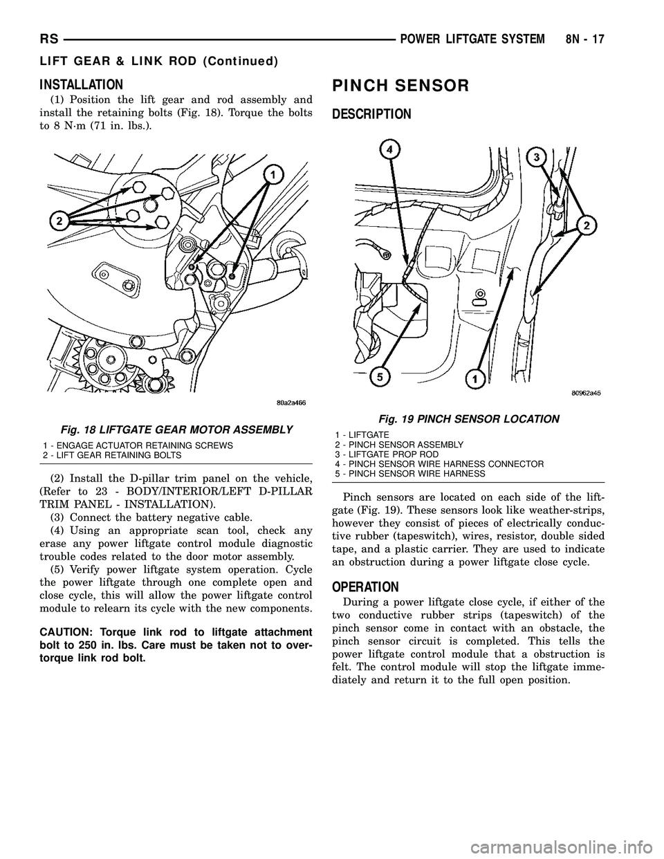
(1) Position the lift gear and rod assembly and
install the retaining bolts (Fig. 18). Torque the bolts
to 8 N´m (71 in. lbs.).
(2) Install the D-pillar trim panel on the vehicle,
(Refer to 23 - BODY/INTERIOR/LEFT D-PILLAR
TRIM PANEL - INSTALLATION).
(3) Connect the battery negative cable.
(4) Using an appropriate scan tool, check any
erase any power liftgate control module diagnostic
trouble codes related to the door motor assembly.
(5) Verify power liftgate system operation. Cycle
the power liftgate through one complete open and
close cycle, this will allow the power liftgate control
module to relearn its cycle with the new components.
CAUTION: Torque link rod to liftgate attachment
bolt to 250 in. lbs. Care must be taken not to over-
torque link rod bolt.
PINCH SENSOR
DESCRIPTION
Pinch sensors are located on each side of the lift-
gate (Fig. 19). These sensors look like weather-strips,
however they consist of pieces of electrically conduc-
tive rubber (tapeswitch), wires, resistor, double sided
tape, and a plastic carrier. They are used to indicate
an obstruction during a power liftgate close cycle.
OPERATION
During a power liftgate close cycle, if either of the
two conductive rubber strips (tapeswitch) of the
pinch sensor come in contact with an obstacle, the
pinch sensor circuit is completed. This tells the
power liftgate control module that a obstruction is
felt. The control module will stop the liftgate imme-
diately and return it to the full open position.
Fig. 18 LIFTGATE GEAR MOTOR ASSEMBLY
1 - ENGAGE ACTUATOR RETAINING SCREWS
2 - LIFT GEAR RETAINING BOLTS
Fig. 19 PINCH SENSOR LOCATION
1 - LIFTGATE
2 - PINCH SENSOR ASSEMBLY
3 - LIFTGATE PROP ROD
4 - PINCH SENSOR WIRE HARNESS CONNECTOR
5 - PINCH SENSOR WIRE HARNESS
RSPOWER LIFTGATE SYSTEM8N-17
LIFT GEAR & LINK ROD (Continued)
Page 441 of 2339
REMOVAL
(1) Disconnect and isolate the battery negative
cable.
(2) Remove trim panel from liftgate, (Refer to 23 -
BODY/DECKLID/HATCH/LIFTGATE/TAILGATE/
TRIM PANEL - REMOVAL).
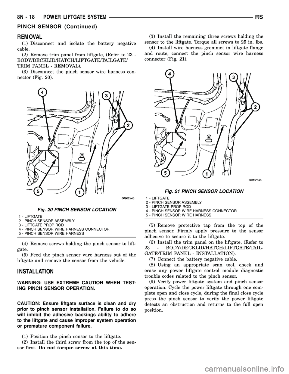
(3) Disconnect the pinch sensor wire harness con-
nector (Fig. 20).
(4) Remove screws holding the pinch sensor to lift-
gate.
(5) Feed the pinch sensor wire harness out of the
liftgate and remove the sensor from the vehicle.
INSTALLATION
WARNING: USE EXTREME CAUTION WHEN TEST-
ING PINCH SENSOR OPERATION.
CAUTION: Ensure liftgate surface is clean and dry
prior to pinch sensor installation. Failure to do so
will inhibit the adhesive backings ability to adhere
to the liftgate and cause improper system operation
or premature component failure.
(1) Position the pinch sensor to the liftgate.
(2) Install the third screw from the top of the sen-
sor first.Do not torque screw at this time.(3) Install the remaining three screws holding the
sensor to the liftgate. Torque all screws to 25 in. lbs.
(4) Install wire harness grommet in liftgate flange
and route, connect the pinch sensor wire harness
connector (Fig. 21).
(5) Remove protective tap from the top of the
pinch sensor. Firmly apply pressure to the sensor
adhesive to secure it to the liftgate.
(6) Install the trim panel on the liftgate, (Refer to
23 - BODY/DECKLID/HATCH/LIFTGATE/TAIL-
GATE/TRIM PANEL - INSTALLATION).
(7) Connect the battery negative cable.
(8) Using an appropriate scan tool, check and
erase any power liftgate control module diagnostic
trouble codes related to the pinch sensor.
(9) Verify power liftgate system and pinch sensor
operation. Cycle the power liftgate through one com-
plete open and close cycle, during the final close cycle
press the pinch sensor to verify the power liftgate
detects an obstruction and returns to the full open
position.
Fig. 20 PINCH SENSOR LOCATION
1 - LIFTGATE
2 - PINCH SENSOR ASSEMBLY
3 - LIFTGATE PROP ROD
4 - PINCH SENSOR WIRE HARNESS CONNECTOR
5 - PINCH SENSOR WIRE HARNESS
Fig. 21 PINCH SENSOR LOCATION
1 - LIFTGATE
2 - PINCH SENSOR ASSEMBLY
3 - LIFTGATE PROP ROD
4 - PINCH SENSOR WIRE HARNESS CONNECTOR
5 - PINCH SENSOR WIRE HARNESS
8N - 18 POWER LIFTGATE SYSTEMRS
PINCH SENSOR (Continued)
Page 449 of 2339

POWER MIRRORS
TABLE OF CONTENTS
page page
POWER MIRRORS
DESCRIPTION.........................26
OPERATION...........................26
DIAGNOSIS AND TESTING
POWER MIRRORS....................27
AUTOMATIC DAY / NIGHT MIRROR
DESCRIPTION.........................28
OPERATION...........................28
DIAGNOSIS AND TESTING
AUTOMATIC DAY / NIGHT MIRROR.......28
POWER FOLDAWAY MIRROR SWITCH -
EXPORT
DESCRIPTION.........................29OPERATION...........................29
REMOVAL.............................29
INSTALLATION.........................30
REMOTE SWITCH
DIAGNOSIS AND TESTING
REMOTE SWITCH.....................30
REMOVAL.............................30
INSTALLATION.........................30
SIDEVIEW MIRROR
REMOVAL.............................30
POWER MIRRORS
DESCRIPTION
If equipped with power mirrors, the control switch
is located on the instrument panel to the left of the
headlamp switch.
OPERATION
The power mirrors are connected to battery feed at
all times. Each mirror head contains two electric
motors, two drive mechanisms, an electric heating
element, and the mirror glass. If the vehicle is
equipped with the optional memory system, the
driver side mirror head also contains both a horizon-
tal and a vertical motor position sensor. One motor
and drive controls mirror up-and-down movement,
and the other controls right-and-left movement.An optional driver side outside electrochromic mir-
ror is able to automatically change its reflectance
level. This mirror is controlled by the circuitry of the
automatic day/night inside rear view mirror. A thin
layer of electrochromic material between two pieces
of conductive glass make up the face of the mirror.
Two photocell sensors on the inside rear view mirror
are used to monitor light levels and adjust the reflec-
tance of both the inside and driver side outside mir-
rors. This change in reflectance helps to reduce the
glare of headlamps approaching the vehicle from the
rear. (Refer to 8 - ELECTRICAL/POWER MIRRORS/
AUTOMATIC DAY / NIGHT MIRROR - DESCRIP-
TION) for more information on this system.
The motors which operate the mirrors are part of
the mirror assembly and cannot be serviced sepa-
rately.
8N - 26 POWER MIRRORSRS