CHRYSLER TOWN AND COUNTRY 2008 5.G Owners Manual
Manufacturer: CHRYSLER, Model Year: 2008, Model line: TOWN AND COUNTRY, Model: CHRYSLER TOWN AND COUNTRY 2008 5.GPages: 531, PDF Size: 4.51 MB
Page 211 of 531
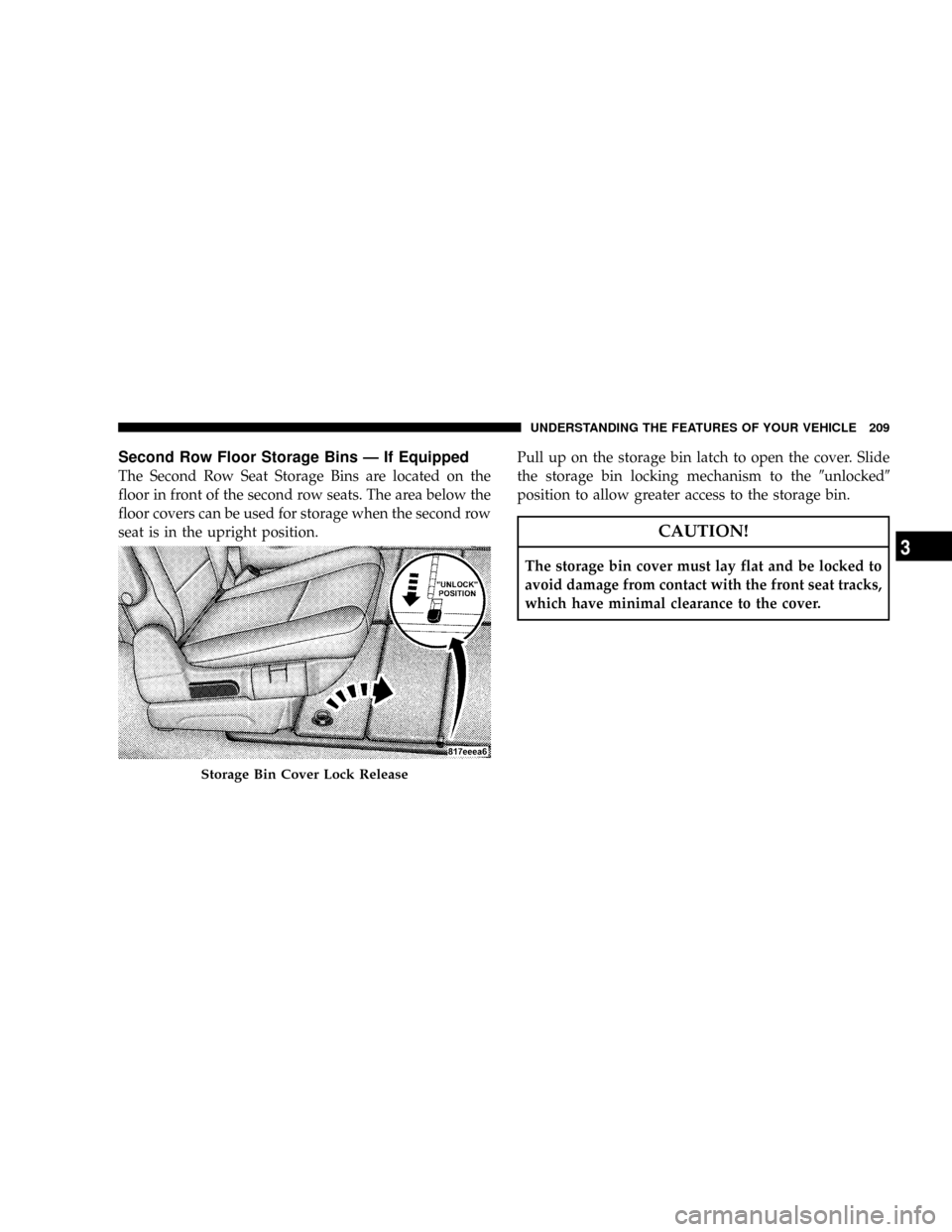
Second Row Floor Storage Bins Ð If Equipped
The Second Row Seat Storage Bins are located on the
floor in front of the second row seats. The area below the
floor covers can be used for storage when the second row
seat is in the upright position.Pull up on the storage bin latch to open the cover. Slide
the storage bin locking mechanism to the9unlocked9
position to allow greater access to the storage bin.
CAUTION!
The storage bin cover must lay flat and be locked to
avoid damage from contact with the front seat tracks,
which have minimal clearance to the cover.
Storage Bin Cover Lock Release
UNDERSTANDING THE FEATURES OF YOUR VEHICLE 209
3
Page 212 of 531
WARNING!
In an accident, serious injury could result if the seat
storage bin covers are not properly latched.
²DO NOT drive the vehicle with the storage bin
covers open.
²Keep the storage bin covers closed and latched
while the vehicle is in motion.
²DO NOT use a storage bin latch as a tie down.
Removing The Floor Console With Stow 'n Go
Seating Ð If Equipped
The removable floor console has two power outlets,
storage tray, light, removable cell phone holder, tissue
holder, pen holder and a map holder. It can be removed
from the vehicle by pulling the release handle inside the
floor console.To remove the console use the following procedure:
1. Open the console lid and remove the storage tray.
2. Pull up on the release handle located inside the floor
console, and slide the console rearward to disengage
from the floor.
3. Remove the floor console.
To reinstall the console use the following procedure:
1. Open the console lid and remove the storage tray.
2. Pull up on the release handle and slide the console
forward to engage the front of the console into the floor
tray.
3. Pivot the floor console down until it is seated on the
floor tray and release the handle.
210 UNDERSTANDING THE FEATURES OF YOUR VEHICLE
Page 213 of 531
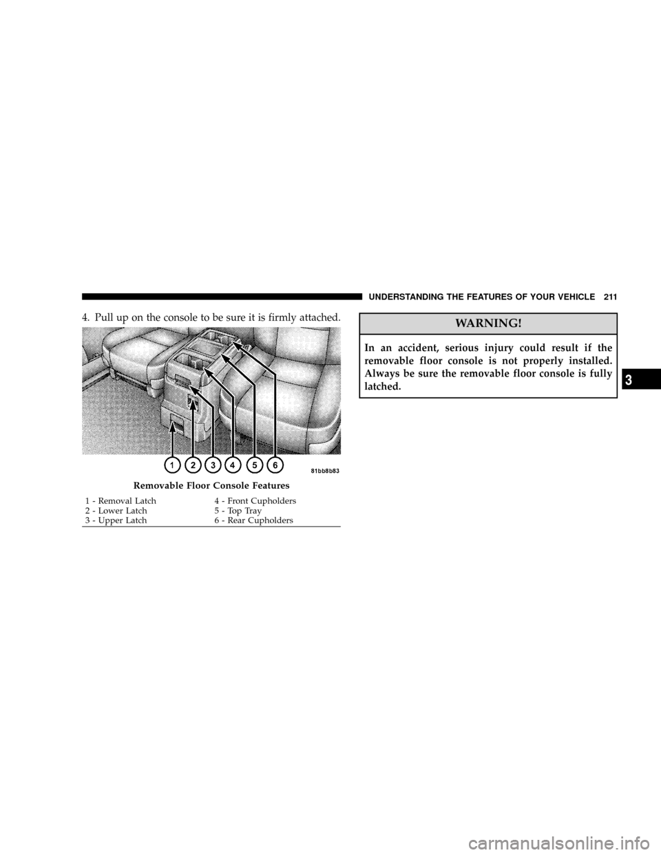
4. Pull up on the console to be sure it is firmly attached.WARNING!
In an accident, serious injury could result if the
removable floor console is not properly installed.
Always be sure the removable floor console is fully
latched.
Removable Floor Console Features
1 - Removal Latch 4 - Front Cupholders
2 - Lower Latch 5 - Top Tray
3 - Upper Latch 6 - Rear CupholdersUNDERSTANDING THE FEATURES OF YOUR VEHICLE 211
3
Page 214 of 531
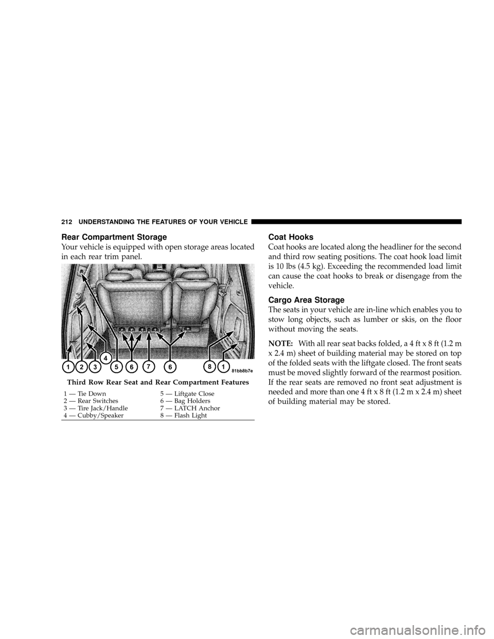
Rear Compartment Storage
Your vehicle is equipped with open storage areas located
in each rear trim panel.
Coat Hooks
Coat hooks are located along the headliner for the second
and third row seating positions. The coat hook load limit
is 10 lbs (4.5 kg). Exceeding the recommended load limit
can cause the coat hooks to break or disengage from the
vehicle.
Cargo Area Storage
The seats in your vehicle are in-line which enables you to
stow long objects, such as lumber or skis, on the floor
without moving the seats.
NOTE:With all rear seat backs folded,a4ftx8ft(1.2 m
x 2.4 m) sheet of building material may be stored on top
of the folded seats with the liftgate closed. The front seats
must be moved slightly forward of the rearmost position.
If the rear seats are removed no front seat adjustment is
needed and more than one 4 ftx8ft(1.2 m x 2.4 m) sheet
of building material may be stored.
Third Row Rear Seat and Rear Compartment Features
1 Ð Tie Down 5 Ð Liftgate Close
2 Ð Rear Switches 6 Ð Bag Holders
3 Ð Tire Jack/Handle 7 Ð LATCH Anchor
4 Ð Cubby/Speaker 8 Ð Flash Light 212 UNDERSTANDING THE FEATURES OF YOUR VEHICLE
Page 215 of 531
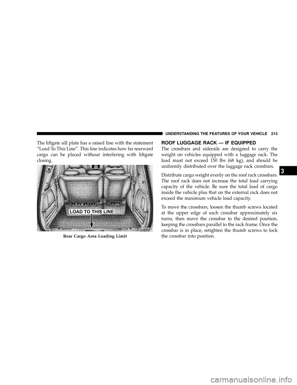
The liftgate sill plate has a raised line with the statement
ªLoad To This Lineº. This line indicates how far rearward
cargo can be placed without interfering with liftgate
closing.ROOF LUGGAGE RACK Ð IF EQUIPPED
The crossbars and siderails are designed to carry the
weight on vehicles equipped with a luggage rack. The
load must not exceed 150 lbs (68 kg), and should be
uniformly distributed over the luggage rack crossbars.
Distribute cargo weight evenly on the roof rack crossbars.
The roof rack does not increase the total load carrying
capacity of the vehicle. Be sure the total load of cargo
inside the vehicle plus that on the external rack does not
exceed the maximum vehicle load capacity.
To move the crossbars, loosen the thumb screws located
at the upper edge of each crossbar approximately six
turns, then move the crossbar to the desired position,
keeping the crossbars parallel to the rack frame. Once the
crossbar is in place, retighten the thumb screws to lock
the crossbar into position.
Rear Cargo Area Loading Limit
UNDERSTANDING THE FEATURES OF YOUR VEHICLE 213
3
Page 216 of 531
Attempt to move the crossbar again to ensure that it has
properly locked into position.
NOTE:To help control wind noise when installing the
crossbars make sure the arrows marked on the underside
of the crossbars are facing the front of the vehicle. When
the crossbars are not in use, the front crossbar should be
fastened just forward of the middle support and the rear
crossbar should be fastened at the rearmost position of
the side rails. This will help reduce the amount of wind
noise when the crossbars are not in use.
The tie down holes on the crossbar ends should always
be used to tie down the load. Check the straps frequently
to be sure that the load remains securely attached.CAUTION!
²Crossbars should remain equally spaced or paral-
lel at any luggage rack position for proper func-
tion. Noncompliance could result in damage to the
luggage rack, cargo and/or vehicle.
²To avoid damage to the roof rack and vehicle, do not
exceed the maximum roof rack load capacity of 150
lbs (68 kg). Always distribute heavy loads as evenly
as possible and secure the load appropriately.
214 UNDERSTANDING THE FEATURES OF YOUR VEHICLE
Page 217 of 531
CAUTION!
²Long loads which extend over the windshield,
such as wood panels or surfboards, or loads with
large frontal area should be secured to both the
front and rear of the vehicle.
²Travel at reduced speeds and turn corners care-
fully when carrying large or heavy loads on the
roof rack. Wind forces, due to natural causes or
nearby truck traffic, can add sudden upward lift to
a load. This is especially true on large flat loads
and may result in damage to the cargo or your
vehicle.
WARNING!
Cargo must be securely tied before driving your
vehicle. Improperly secured loads can fly off the
vehicle, particularly at high speeds, resulting in per-
sonal injury or property damage. Follow the Roof
Rack Cautions when carrying cargo on your roof
rack.
UNDERSTANDING THE FEATURES OF YOUR VEHICLE 215
3
Page 218 of 531
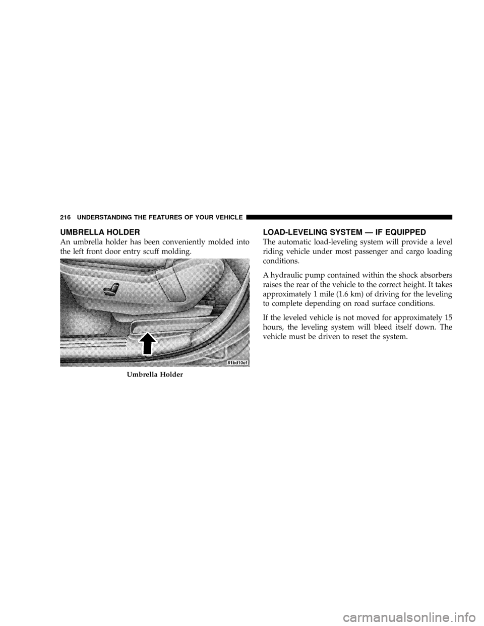
UMBRELLA HOLDER
An umbrella holder has been conveniently molded into
the left front door entry scuff molding.
LOAD-LEVELING SYSTEM Ð IF EQUIPPED
The automatic load-leveling system will provide a level
riding vehicle under most passenger and cargo loading
conditions.
A hydraulic pump contained within the shock absorbers
raises the rear of the vehicle to the correct height. It takes
approximately 1 mile (1.6 km) of driving for the leveling
to complete depending on road surface conditions.
If the leveled vehicle is not moved for approximately 15
hours, the leveling system will bleed itself down. The
vehicle must be driven to reset the system.
Umbrella Holder
216 UNDERSTANDING THE FEATURES OF YOUR VEHICLE
Page 219 of 531
WARNING!
Do not install the load-leveling system on vehicles
that are not equipped with Anti-Lock Brakes. Ve-
hicles without Anti-Lock Brakes (ABS) have a height-
sensing proportioning valve. Installing a leveling
system will render this system ineffective, inappro-
priately reducing rear brake pressure, resulting in
increased stopping distances. You could have a seri-
ous accident.
UNDERSTANDING THE FEATURES OF YOUR VEHICLE 217
3
Page 220 of 531
