radiator CHRYSLER VOYAGER 1996 Service Manual
[x] Cancel search | Manufacturer: CHRYSLER, Model Year: 1996, Model line: VOYAGER, Model: CHRYSLER VOYAGER 1996Pages: 1938, PDF Size: 55.84 MB
Page 1839 of 1938
COMPRESSOR
REMOVAL
WARNING: REFER TO REFRIGERANT SERVICE
PROCEDURES FOR INFORMATION REGARDING
PROPER RECOVERY OF THE REFRIGERANT
BEFORE ATTEMPTING TO REMOVE THE COM-
PRESSOR.
(1) Disconnect negative battery cable.
(2) Pinch off coolant lines to rear Heat unit (if
equipped). Drain engine coolant.
(3) Remove upper radiator hose.
(4) Remove drive belt (refer to Group 7, Cooling
System). Disconnect compressor clutch wire lead.
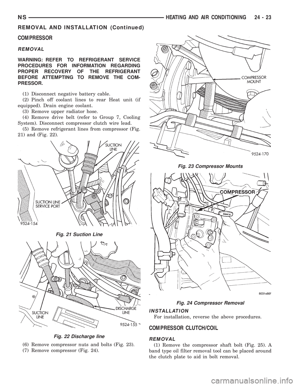
(5) Remove refrigerant lines from compressor (Fig.
21) and (Fig. 22).
(6) Remove compressor nuts and bolts (Fig. 23).
(7) Remove compressor (Fig. 24).
INSTALLATION
For installation, reverse the above procedures.
COMPRESSOR CLUTCH/COIL
REMOVAL
(1) Remove the compressor shaft bolt (Fig. 25). A
band type oil filter removal tool can be placed around
the clutch plate to aid in bolt removal.
Fig. 21 Suction Line
Fig. 22 Discharge line
Fig. 23 Compressor Mounts
Fig. 24 Compressor Removal
NSHEATING AND AIR CONDITIONING 24 - 23
REMOVAL AND INSTALLATION (Continued)
Page 1841 of 1938
CAUTION: The clutch pulley and the front plate
were mated at the factory by a burnishing opera-
tion. No attempt should be made to separately
replace either part. This will result in clutch slip-
page due to insufficient contact area.
INSTALLATION
(1) Align pin in back of field coil with hole in com-
pressor end housing, and position field coil into place.
Make sure that lead wires are properly routed, and
fasten with the wire clip screw.
(2) Install field coil retaining snap ring with snap
ring pliers. The bevel side of the snap ring facing
outward. Also both snap ring eyelets must be to the
right or left of the pin on compressor. Press snap ring
to make sure it is properly seated in the groove.
CAUTION: If snap ring is not fully seated it will
vibrate out, resulting in a clutch failure and severe
damage to the front face of the compressor.
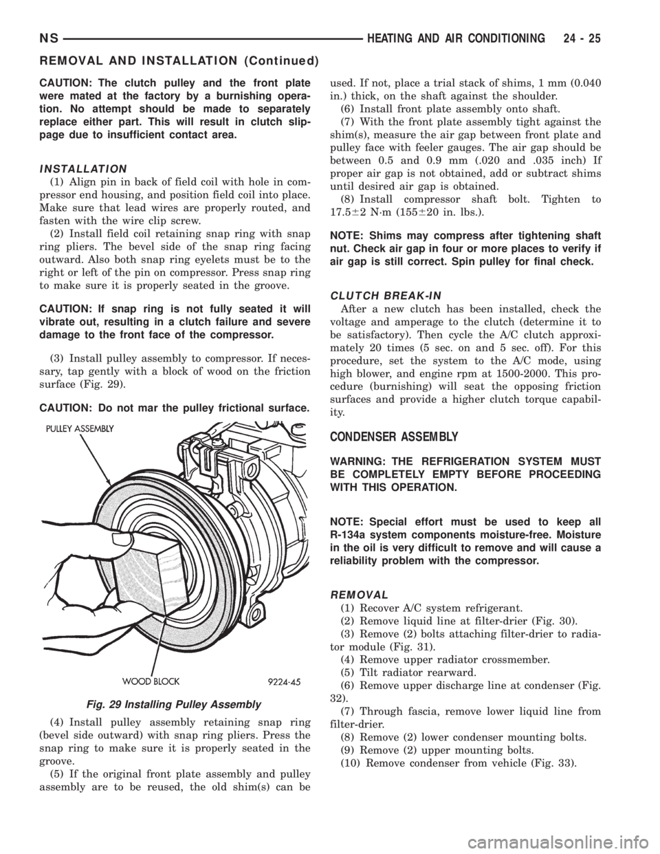
(3) Install pulley assembly to compressor. If neces-
sary, tap gently with a block of wood on the friction
surface (Fig. 29).
CAUTION: Do not mar the pulley frictional surface.
(4) Install pulley assembly retaining snap ring
(bevel side outward) with snap ring pliers. Press the
snap ring to make sure it is properly seated in the
groove.
(5) If the original front plate assembly and pulley
assembly are to be reused, the old shim(s) can beused. If not, place a trial stack of shims, 1 mm (0.040
in.) thick, on the shaft against the shoulder.
(6) Install front plate assembly onto shaft.
(7) With the front plate assembly tight against the
shim(s), measure the air gap between front plate and
pulley face with feeler gauges. The air gap should be
between 0.5 and 0.9 mm (.020 and .035 inch) If
proper air gap is not obtained, add or subtract shims
until desired air gap is obtained.
(8) Install compressor shaft bolt. Tighten to
17.562 N´m (155620 in. lbs.).
NOTE: Shims may compress after tightening shaft
nut. Check air gap in four or more places to verify if
air gap is still correct. Spin pulley for final check.
CLUTCH BREAK-IN
After a new clutch has been installed, check the
voltage and amperage to the clutch (determine it to
be satisfactory). Then cycle the A/C clutch approxi-
mately 20 times (5 sec. on and 5 sec. off). For this
procedure, set the system to the A/C mode, using
high blower, and engine rpm at 1500-2000. This pro-
cedure (burnishing) will seat the opposing friction
surfaces and provide a higher clutch torque capabil-
ity.
CONDENSER ASSEMBLY
WARNING: THE REFRIGERATION SYSTEM MUST
BE COMPLETELY EMPTY BEFORE PROCEEDING
WITH THIS OPERATION.
NOTE: Special effort must be used to keep all
R-134a system components moisture-free. Moisture
in the oil is very difficult to remove and will cause a
reliability problem with the compressor.
REMOVAL
(1) Recover A/C system refrigerant.
(2) Remove liquid line at filter-drier (Fig. 30).
(3) Remove (2) bolts attaching filter-drier to radia-
tor module (Fig. 31).
(4) Remove upper radiator crossmember.
(5) Tilt radiator rearward.
(6) Remove upper discharge line at condenser (Fig.
32).
(7) Through fascia, remove lower liquid line from
filter-drier.
(8) Remove (2) lower condenser mounting bolts.
(9) Remove (2) upper mounting bolts.
(10) Remove condenser from vehicle (Fig. 33).
Fig. 29 Installing Pulley Assembly
NSHEATING AND AIR CONDITIONING 24 - 25
REMOVAL AND INSTALLATION (Continued)
Page 1845 of 1938
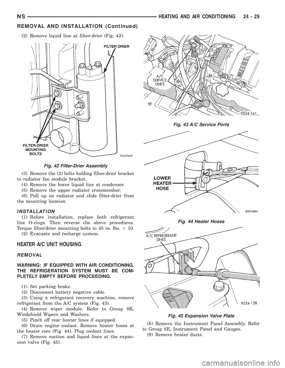
(2) Remove liquid line at filter-drier (Fig. 42).
(3) Remove the (2) bolts holding filter-drier bracket
to radiator fan module bracket.
(4) Remove the lower liquid line at condenser.
(5) Remove the upper radiator crossmember.
(6) Pull up on radiator and slide filter-drier from
the mounting location.
INSTALLATION
(1) Before installation, replace both refrigerant
line O-rings. Then reverse the above procedures.
Torque filter/drier mounting bolts to 45 in. lbs.610.
(2) Evacuate and recharge system.
HEATER A/C UNIT HOUSING
REMOVAL
WARNING: IF EQUIPPED WITH AIR CONDITIONING,
THE REFRIGERATION SYSTEM MUST BE COM-
PLETELY EMPTY BEFORE PROCEEDING.
(1) Set parking brake.
(2) Disconnect battery negative cable.
(3) Using a refrigerant recovery machine, remove
refrigerant from the A/C system (Fig. 43).
(4) Remove wiper module. Refer to Group 8K,
Windshield Wipers and Washers.
(5) Pinch off rear heater lines if equipped.
(6) Drain engine coolant. Remove heater hoses at
the heater core (Fig. 44). Plug coolant lines.
(7) Remove suction and liquid lines at the expan-
sion valve (Fig. 45).(8) Remove the Instrument Panel Assembly. Refer
to Group 8E, Instrument Panel and Gauges.
(9) Remove heater ducts.
Fig. 42 Filter-Drier Assembly
Fig. 43 A/C Service Ports
Fig. 44 Heater Hoses
Fig. 45 Expansion Valve Plate
NSHEATING AND AIR CONDITIONING 24 - 29
REMOVAL AND INSTALLATION (Continued)
Page 1848 of 1938

CAUTION: When removing hoses from heater core
inlet or outlet nipples, do not use excessive force.
Heater core may become damaged and leak engine
coolant.
(3) Carefully rotate hose back and forth while tug-
ging slightly away from connector nipple. If the hose
will not come off, slice the hose at the connector nip-
ple and peel off heater hose. This method will require
heater hose replacement.
INSTALLATION
For installation, reverse the above procedures.
LIQUID LINE
REMOVAL
(1) Disconnect the battery negative cable.
(2) Recover A/C system refrigerant.
(3) Remove the accessory drive belt.
(4) Remove upper generator bracket.
(5) Remove ground wire at dash panel.
(6) Remove the nut retaining the refrigerant line
sealing plate to the expansion valve (Fig. 39).
(7) Remove the stud from the expansion valve (Fig.
40).
(8) Remove liquid line from expansion valve.
(9) Cover the openings to prevent contamination.
(10) Disconnect wire connector at pressure trans-
ducer.
(11) Remove liquid line mounting bracket at right
frame rail.
(12) Using access slot between radiator crossmem-
ber and grille, loosen liquid line mounting plate at
filter-drier. Remove liquid line from filter-drier. It
may be necessary to bend liquid line in half to
remove line. The replacement line is a two-piece
assembly.
(13) Remove the old O-rings.
INSTALLATION
For installation, reverse the above procedures.
²Install the stud to the evaporator sealing plate
and tighten 7 to 11 N´m (64 to 96 in. lbs.) torque.
²Install new O-rings.
²Install two-piece line in place of original part.
²A
ssemble line halves after it is installed on vehicle.²Evacuate and recharge A/C system.
MODE DOOR ACTUATOR
REMOVAL
(1) Remove the lower left side steering column
cover. Refer to Group 8E, Instrument Panel and Sys-
tems.
(2) Remove ABS control module (Fig. 56).
(3) Remove mode actuator connector (Fig. 57).
(4) Remove mode door actuator (Fig. 58).
INSTALLATION
(1) For installation, reverse the above procedures.
Fig. 55 Lower Heater Hose
Fig. 56 ABS Control Module
Fig. 57 Mode Door Actuator Connector
24 - 32 HEATING AND AIR CONDITIONINGNS
REMOVAL AND INSTALLATION (Continued)
Page 1861 of 1938
CAUTION: Do not damage the evaporator insulation
liner during installation.
(3) Carefully install the evaporator and expansion
valve straight into the unit. Do not scratch the seal-
ing surfaces with the plumbing extension tube pilots.
(4) Determine the amount of old refrigerant oil
drained from the evaporator. Add this amount (of
clean refrigerant oil) back into the system.
(5) Carefully align the expansion valve onto the
pilot tubes of the plumbing extension (do not scratch
the sealing surface). Install the bolt through the
plumbing plate into the unit sealing plate. Tighten
bolts to 2363 N´m (200630 inch pounds) torque.
(6) Install evaporator cover and blower scroll.
(7) Install quarter trim panel, evacuate/charge sys-
tem, and perform the performance test.
REAR AIR CONDITIONING LINES
WARNING: THE REFRIGERATION SYSTEM MUST
BE COMPLETELY EMPTY BEFORE PROCEEDING
WITH THIS OPERATION.
REMOVAL
(1) Hoist vehicle
(2) Remove compression fittings to the suction and
liquid lines located on the right, outboard side of the
underbody, rearward of the front crossmember. (Fig.
2)
(3) remove (1) bolt securing a/c lines to block
located on the right, outboard side of the underbody,
rearward of the rear wheel and tire. (Fig. 5)
(4) Remove (3) straps securing underbody lines.
(Fig. 1)
(5) Separate and remove a/c lines from vehicle.
INSTALLATION
(1) Before installation, replace all O-rings and gas-
kets. Coat all sealing surfaces with approved wax-
free refrigerant oil. Then, reverse the above
procedures.
(2) Evacuate and recharge system.
REAR HEATER A/C AIR OUTLETS
REMOVAL
Separate barrel from bezel by pulling outward.
INSTALLATION
For installation, push the outlet firmly into the
opening until it locks into place.
REAR HEATER-A/C AUXILIARY CONDENSER
If vehicle is equipped with a 3.3L or 3.8L engine
with rear heater and air conditioning, it will be
equipped with an auxiliary condenser. The auxiliarycondenser is mounted on the primary condenser in
front of the radiator. Both condenser must be
removed as an assembly and then separated.
WARNING: THE REFRIGERATION SYSTEM MUST
BE COMPLETELY EMPTY BEFORE PROCEEDING
WITH THIS OPERATION.
NOTE: Special effort must be used to keep all
R-134a system components moisture-free. Moisture
in the oil is very difficult to remove and will cause a
reliability problem with the compressor.
The condenser assembly must first be removed
from vehicle. Refer to CONDENSER ASSEMBLY
removal and installation in this section for service
procedures.
REMOVAL
(1) After condenser assembly removal, place on
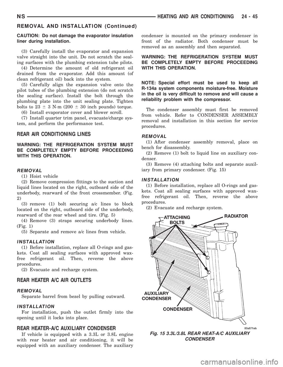
bench for disassembly.
(2) Remove (1) bolt to liquid line on auxiliary con-
denser.
(3) Remove (4) attaching bolts and separate auxil-
iary from primary condenser. (Fig. 15)
INSTALLATION
(1) Before installation, replace all O-rings and gas-
kets. Coat all sealing surfaces with approved wax-
free refrigerant oil. Then, reverse the above
procedures.
(2) Evacuate and recharge system.
Fig. 15 3.3L/3.8L REAR HEAT-A/C AUXILIARY
CONDENSER
NSHEATING AND AIR CONDITIONING 24 - 45
REMOVAL AND INSTALLATION (Continued)
Page 1864 of 1938
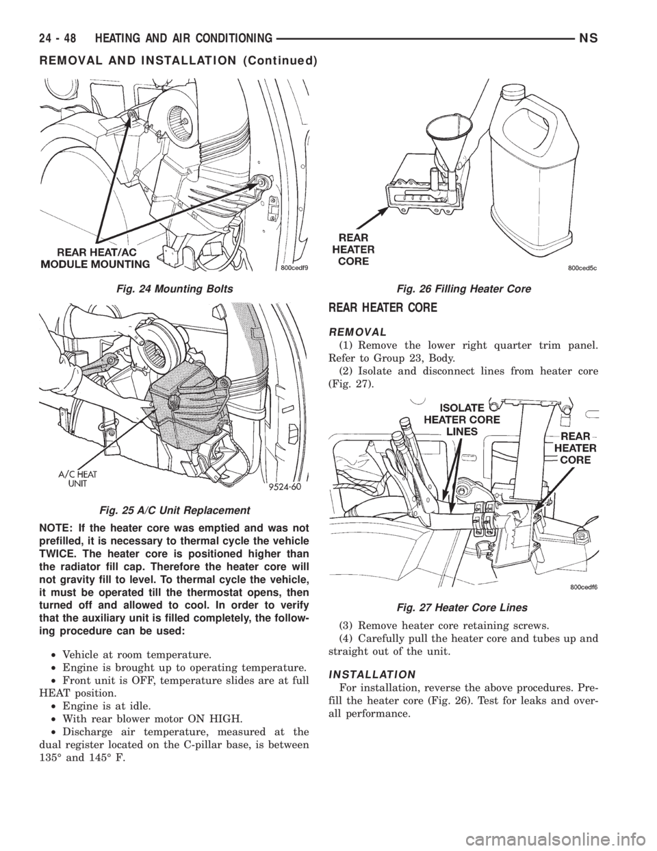
NOTE: If the heater core was emptied and was not
prefilled, it is necessary to thermal cycle the vehicle
TWICE. The heater core is positioned higher than
the radiator fill cap. Therefore the heater core will
not gravity fill to level. To thermal cycle the vehicle,
it must be operated till the thermostat opens, then
turned off and allowed to cool. In order to verify
that the auxiliary unit is filled completely, the follow-
ing procedure can be used:
²Vehicle at room temperature.
²Engine is brought up to operating temperature.
²Front unit is OFF, temperature slides are at full
HEAT position.
²Engine is at idle.
²With rear blower motor ON HIGH.
²Discharge air temperature, measured at the
dual register located on the C-pillar base, is between
135É and 145É F.
REAR HEATER CORE
REMOVAL
(1) Remove the lower right quarter trim panel.
Refer to Group 23, Body.
(2) Isolate and disconnect lines from heater core
(Fig. 27).
(3) Remove heater core retaining screws.
(4) Carefully pull the heater core and tubes up and
straight out of the unit.
INSTALLATION
For installation, reverse the above procedures. Pre-
fill the heater core (Fig. 26). Test for leaks and over-
all performance.
Fig. 24 Mounting Bolts
Fig. 25 A/C Unit Replacement
Fig. 26 Filling Heater Core
Fig. 27 Heater Core Lines
24 - 48 HEATING AND AIR CONDITIONINGNS
REMOVAL AND INSTALLATION (Continued)
Page 1865 of 1938
NOTE: If the heater core was emptied and was not
prefilled, it is necessary to thermal cycle the vehicle
TWICE. The heater core is positioned higher than
the radiator fill cap. Therefore the heater core will
not gravity fill to level. To thermal cycle the vehicle,
it must be operated till the thermostat opens, then
turned off and allowed to cool. In order to verify
that the auxiliary unit is filled completely, the follow-
ing procedure can be used:
²Vehicle at room temperature.
²Engine is brought up to operating temperature.
²Front unit is OFF, temperature slides are at full
HEAT position.
²Engine is at idle.
²With rear blower motor ON HIGH
²Discharge air temperature, measured at the
dual register located on the C-pillar base, is between
57ÉC to 62ÉC (135É and 145É F).
REAR HEATER LINES
REMOVAL
NOTE: Review Safety Precautions and Warnings
before proceeding with this operation.
(1) Partially drain engine cooling system. Refer to
Group 7, Engine Cooling.
(2) Loosen clamp at the front end of the hose
located at the right, outboard side of the underbody,
rearward of the front crossmember. (Fig. 2)
(3) Carefully rotate hose back and forth while tug-
ging slightly away from connector nipple. If the hose
will not come off, slice the hose at the connector nip-
ple and peel off heater hose. This method will require
heater hose replacement.
CAUTION: When removing hoses from outlet nip-
ples, do not use excessive force. Outlet nipples
may become damaged and leak engine coolant.
(4) Compress insert in rear heater hose quick con-
nection and pull downward on hose. (Fig. 4)(5) Remove (3) straps securing underbody lines.
(Fig. 1)
(6) Separate and remove rear heater lines from
vehicle.
INSTALLATION
For installation, reverse the above procedures.
MODE DOOR
REMOVAL
(1) Remove A/C unit.
(2) Place unit on bench.
(3) Remove heater core.
(4) Remove blower scroll.
(5) Remove evaporator cover.
(6) Remove A/C line to expansion valve mounting
nut.
(7) Carefully pull evaporator out of housing.
(8) Remove mode door actuator and gear exten-
sion.
(9) Remove Heater-A/C housing clips and screws.
(10) Separate housing halves.
(11) Remove mode door.
INSTALLATION
For installation, reverse the above procedures.
MODE DOOR ACTUATOR
REMOVAL
(1) Remove A/C unit.
(2) Place unit on bench.
(3) Remove mode door actuator connector.
(4) Remove mode door actuator mounting screws
and remove actuator.
INSTALLATION
For installation, reverse the above procedures.
NSHEATING AND AIR CONDITIONING 24 - 49
REMOVAL AND INSTALLATION (Continued)
Page 1880 of 1938
(6) If coil current reads zero, the coil is open and
should be replaced. If the ammeter reading is 4
amperes or more, the coil is shorted and should be
replaced. If the coil voltage is not within two volts of
the battery voltage, test clutch coil feed circuit for
excessive voltage drop.
EXPANSION VALVE
NOTE: Special effort must be used to keep all
R-134a system components moisture-free. Moisture
in the oil is very difficult to remove and will cause a
reliability problem with the compressor.
TESTS
NOTE: Expansion valve tests should be performed
after compressor tests.
Review Safety Precautions and Warnings in this
group. The work area and vehicle temperature must
be 21ÉC to 27ÉC (70ÉF to 85ÉF). To test the expansion
valve:
NOTE: Liquid CO2 is required to test the expansion
valve. It is available from most welding supply facil-
ities. CO2 is also available from companies which
service and sell fire extinguishers.
(1) Connect a charging station or manifold gauge
set to the refrigerant system service ports. Verify the
refrigerant charge level.
(2) Close all doors, windows and vents to the pas-
senger compartment.
(3) Set heater A/C control to A/C, full heat,
FLOOR, and high blower.
(4) Start the engine and allow to idle (1000 rpm).
After the engine has reached running temperature,
allow the passenger compartment to heat up. This
will create the need for maximum refrigerant flow
into the evaporator.
(5) I
f the refrigerant charge is sufficient, discharge
(high pressure) gauge should read 965 to 1655 kPa (140
to 240 psi). Suction (low pressure) gauge should read
140 kPa to 207 kPa (20 psi to 30 psig). If system cannot
achieve proper pressure readings, replace the expan-
sion valve. If pressure is correct, proceed with test.
WARNING: PROTECT SKIN AND EYES FROM CON-
TACTING CO2 PERSONAL INJURY CAN RESULT.
(6) If suction side low pressure is within specified
range, freeze the expansion valve control head for 30
seconds. Use a super cold substance (liquid CO2).Do
not spray R-134a Refrigerant on the expansion
valve for this test.Suction side low pressure should
drop by 10 psi. If not, replace expansion valve.(7) Allow expansion valve to thaw. The low pres-
sure gauge reading should stabilize at 140 kPa to
240 kPa (20 psi to 30 psig). If not, replace expansion
valve.
(8) When expansion valve test is complete, test
A/C overall performance. Remove all test equipment
before returning vehicle to use.
HEATER PERFORMANCE TEST
PRE-DIAGNOSTIC PREPARATIONS
Review Safety Precautions and Warnings in this
group before performing the following procedures.
Check the coolant level, drive belt tension, vacuum
line connections, radiator air flow and fan operation.
Start engine and allow to warm up to normal tem-
perature.
WARNING: DO NOT REMOVE RADIATOR CAP
WHEN ENGINE IS HOT, PERSONAL INJURY CAN
RESULT.
If vehicle has been run recently, wait 15 minutes
before removing cap. Place a rag over the cap and
turn it to the first safety stop. Allow pressure to
escape through the overflow tube. When the system
stabilizes, remove the cap completely.
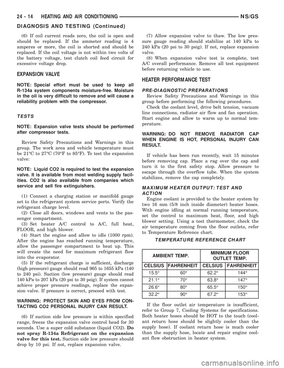
MAXIMUM HEATER OUTPUT: TEST AND
ACTION
Engine coolant is provided to the heater system by
two 16 mm (5/8 inch inside diameter) heater hoses.
With engine idling at normal running temperature,
set the control to maximum heat, floor, and high
blower setting. Using a test thermometer, check the
air temperature coming from the floor outlets, refer
to Temperature Reference chart.
If the floor outlet air temperature is insufficient,
refer to Group 7, Cooling Systems for specifications.
Both heater hoses should be HOT to the touch (cool-
ant return hose should be slightly cooler than the
supply hose). If coolant return hose is much cooler
than the supply hose, locate and repair engine cool-
ant flow obstruction in heater system.
TEMPERATURE REFERENCE CHART
AMBIENT TEMP.MINIMUM FLOOR
OUTLET TEMP.
CELSIUS FAHRENHEIT CELSIUS FAHRENHEIT
15.5É 60É 62.2É 144É
21.1É 70É 63.8É 147É
26.6É 80É 65.5É 150É
32.2É 90É 67.2É 153É
24 - 14 HEATING AND AIR CONDITIONINGNS/GS
DIAGNOSIS AND TESTING (Continued)
Page 1881 of 1938
POSSIBLE LOCATIONS OR CAUSE OF
OBSTRUCTED COOLANT FLOW
(1) Pinched or kinked heater hoses.
(2) Improper heater hose routing.
(3) Plugged heater hoses or supply and return
ports at cooling system connections, refer to Group 7,
Cooling System.
(4) Plugged heater core.
(5) Air locked heater core.
(6) If coolant flow is verified and outlet tempera-
ture is insufficient, a mechanical problem may exist.
POSSIBLE LOCATION OR CAUSE OF
INSUFFICIENT HEAT
(1) Obstructed cowl air intake.
(2) Obstructed heater system outlets.
(3) Blend-air door not functioning properly.
TEMPERATURE CONTROL
If temperature cannot be adjusted with the TEMP
lever on the control panel, the following could require
service:
(1) Blend-air door binding.
(2) Faulty blend-air door motor.
(3) Improper engine coolant temperature.
(4) Faulty Instrument Panel Control.
SYSTEM CHARGE LEVEL TEST
The procedure below should be used to check
and/or fill the refrigerant charge in the air condition-
ing system.
NOTE: The amount of R134a refrigerant that the air
conditioning system holds is 0.96 kg (34 oz. or 2.13
lbs.).
NOTE: Low Charge, condition may be described
as:
²Loss of A/C performance
²Fog from A/C outlets
²evaporator may have a HISS sound
There are two different ways the system can be
tested:
²With a scan tool (DRB), thermocouple and the
Charge Determination Graph. Use the scan tool
(DRB) diagnostic topic: Engine±System Monitors, A/C
Pressure.
²Using a manifold gauge set, a thermocouple and
the Charge Determination Graph.
It is recommended to use the gauges or reclaim/re-
cycle equipment.
WARNING: AVOID BREATHING A/C REFRIGERANT
AND LUBRICANT VAPOR OR MIST. EXPOSURE MAY
IRRITATE EYES, NOSE AND THROAT. USE ONLY
APPROVED SERVICE EQUIPMENT MEETING SAEREQUIREMENTS TO DISCHARGE R-134a SYSTEM. IF
ACCIDENTAL SYSTEM DISCHARGE OCCURS, VEN-
TILATE WORK AREA BEFORE RESUMING SERVICE.
R-134a SERVICE EQUIPMENT OR VEHICLE A/C
SYSTEM SHOULD NOT BE PRESSURE TESTED OR
LEAK TESTED WITH COMPRESSED AIR. SOME
MIXTURES OF AIR/R-134a HAVE BEEN SHOWN TO
BE COMBUSTIBLE AT ELEVATED PRESSURES.
THESE MIXTURES ARE POTENTIALLY DANGER-
OUS AND MAY RESULT IN FIRE OR EXPLOSION
CAUSING INJURY OR PROPERTY DAMAGE.
(1) Establish your preferred method of measuring
liquid line pressure. Use a manifold gauge set or a
DRB scan tool.
(2) A
ttach a clamp-on thermocouple (Professional
Service Equipment 66-324-0014 or 80PK-1A) or equiv-
alent to the liquid line. It must be placed as close to
the A/C Pressure Transducer as possible to observe liq-
uid line temperature. Refer to ªThermocouple Probeº in
this section for more information on probe.
(3) The vehicle must be in the following modes:
²Transaxle in Park
²Engine Idling at 700 rpm
²A/C Controls Set to Outside Air
²Panel Mode
²Full Cool
²High Blower motor, (vehicle equipped with rear
A/C turn rear blower motor ON HIGH)
²A/C Button in the ON position
²Vehicle Windows Open.
²Recirc. button turned OFF
(4) Operate system for a couple of minutes to allow
the system to stabilize.
(5) Set system pressure to about 1793 kPa (260
psi) by placing a piece of cardboard over part of the
front side of the condenser. To place cardboard prop-
erly, remove the upper radiator-condenser cover.
Insert cardboard between condenser and radiator
front. This will maintain a constant pressure.
(6) Observe Liquid Line pressure and Liquid line
temperature. Using theCharge Determination
Chartdetermine where the system is currently oper-
ating. If the system is in the undercharged region,
ADD 0.057 Kg. (2 oz.) to the system and recheck
readings. If the system is in the overcharged region,
RECLAIM 0.057 Kg. (2 oz.) from the system and
recheck readings. Continue this process until the sys-
tem readings are in the proper charge area on the
Charge Determination Chart.
(7) The same procedure can be performed using
the scan tool (DRB). To determine liquid line pres-
sure, attach the scan tool, go to System Moni-
tors±A/C Pressure. Observe liquid line pressure from
A/C Pressure Transducer on digital display and digi-
tal thermometer. Refer toCharge Determination
Chartand determine where the system is operating.
NS/GSHEATING AND AIR CONDITIONING 24 - 15
DIAGNOSIS AND TESTING (Continued)
Page 1889 of 1938
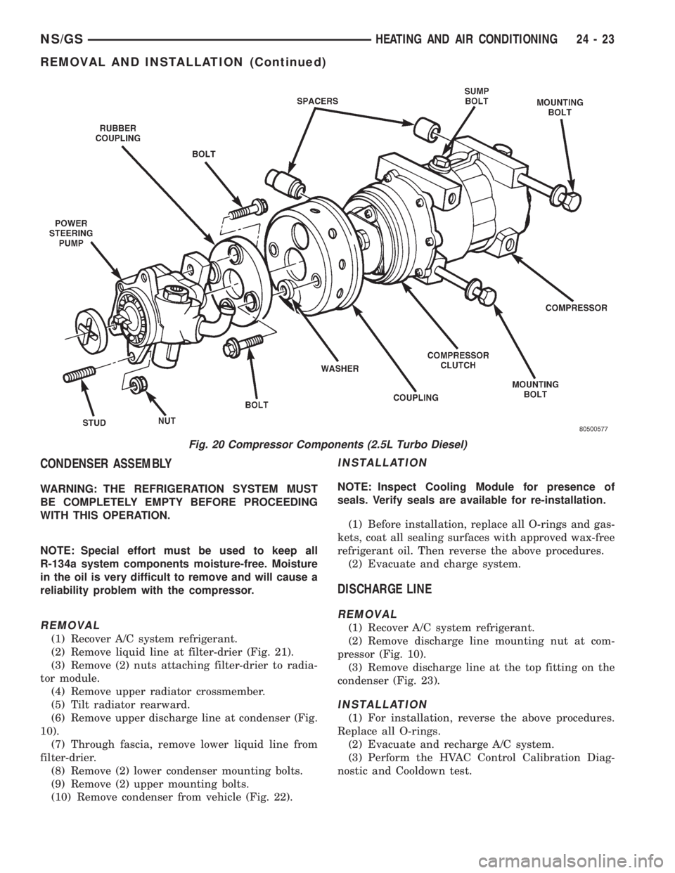
CONDENSER ASSEMBLY
WARNING: THE REFRIGERATION SYSTEM MUST
BE COMPLETELY EMPTY BEFORE PROCEEDING
WITH THIS OPERATION.
NOTE: Special effort must be used to keep all
R-134a system components moisture-free. Moisture
in the oil is very difficult to remove and will cause a
reliability problem with the compressor.
REMOVAL
(1) Recover A/C system refrigerant.
(2) Remove liquid line at filter-drier (Fig. 21).
(3) Remove (2) nuts attaching filter-drier to radia-
tor module.
(4) Remove upper radiator crossmember.
(5) Tilt radiator rearward.
(6) Remove upper discharge line at condenser (Fig.
10).
(7) Through fascia, remove lower liquid line from
filter-drier.
(8) Remove (2) lower condenser mounting bolts.
(9) Remove (2) upper mounting bolts.
(10) Remove condenser from vehicle (Fig. 22).
INSTALLATION
NOTE: Inspect Cooling Module for presence of
seals. Verify seals are available for re-installation.
(1) Before installation, replace all O-rings and gas-
kets, coat all sealing surfaces with approved wax-free
refrigerant oil. Then reverse the above procedures.
(2) Evacuate and charge system.
DISCHARGE LINE
REMOVAL
(1) Recover A/C system refrigerant.
(2) Remove discharge line mounting nut at com-
pressor (Fig. 10).
(3) Remove discharge line at the top fitting on the
condenser (Fig. 23).
INSTALLATION
(1) For installation, reverse the above procedures.
Replace all O-rings.
(2) Evacuate and recharge A/C system.
(3) Perform the HVAC Control Calibration Diag-
nostic and Cooldown test.
Fig. 20 Compressor Components (2.5L Turbo Diesel)
NS/GSHEATING AND AIR CONDITIONING 24 - 23
REMOVAL AND INSTALLATION (Continued)