radiator CHRYSLER VOYAGER 1996 Service Manual
[x] Cancel search | Manufacturer: CHRYSLER, Model Year: 1996, Model line: VOYAGER, Model: CHRYSLER VOYAGER 1996Pages: 1938, PDF Size: 55.84 MB
Page 1892 of 1938

(2) Hand-start the stud into the expansion valve
and torque to7-11N´m(64-96in.lbs.).
(3) Carefully install the expansion valve to the
sealing plate. Install the two screws and tighten 8 to
14 N´m (70 to 130 in. lbs.) torque.
(4) Carefully install the refrigerant lines and seal-
ing plate to the expansion valve. Install the nut and
tighten 20 to 26 N´m (170 to 230 in. lbs.) torque.
(5) Install the ground wire at dash panel.
(6) Pull generator back into the proper position for
bracket mounting.
(7) Install generator field wire connector.
(8) Install the upper generator bracket.
(9) Install accessory drive belt.
(10) Evacuate and recharge system.
(11) After expansion valve is installed, the system
is charged, and leaks have checked repeat the A/C
performance check.
FILTER-DRIER ASSEMBLY
REMOVAL
WARNING: THE REFRIGERATION SYSTEM MUST
BE COMPLETELY EMPTY BEFORE PROCEEDING
WITH THIS OPERATION.
(1) Recover A/C system refrigerant.
(2) Remove liquid line at filter-drier (Fig. 21).
(3) Remove the (2) bolts holding filter-drier bracket
to radiator fan module bracket.
(4) Remove the lower liquid line at condenser.
(5) Remove the upper radiator crossmember.
(6) Pull up on radiator and slide filter-drier from
the mounting location.
INSTALLATION
(1) Before installation, replace both refrigerant
line O-rings. Then reverse the above procedures.
(2) Evacuate and recharge system.
HEATER A/C UNIT HOUSING
REMOVAL
WARNING: IF EQUIPPED WITH AIR CONDITIONING,
THE REFRIGERATION SYSTEM MUST BE COM-
PLETELY EMPTY BEFORE PROCEEDING.
(1) Set parking brake.
(2) Disconnect battery negative cable.
(3) Using a refrigerant recovery machine, remove
refrigerant from the A/C system.
(4) Remove wiper module. Refer to Group 8K,
Windshield Wipers and Washers.
(5) Drain engine coolant. Remove heater hoses at
the heater core, refer to Heater Hoses Removal and
Installation procedures. Plug coolant lines.(6) Remove suction and liquid lines at the expan-
sion valve (Fig. 27).
(7) Remove the Instrument Panel Assembly. Refer
to Group 8E, Instrument Panel and Systems.
(8) Remove heater ducts.
(9) Disconnect the two upper mounts from the
upper reinforcement and the lower mount from the
tunnel.
(10) Remove the (3) nuts (in the engine compart-
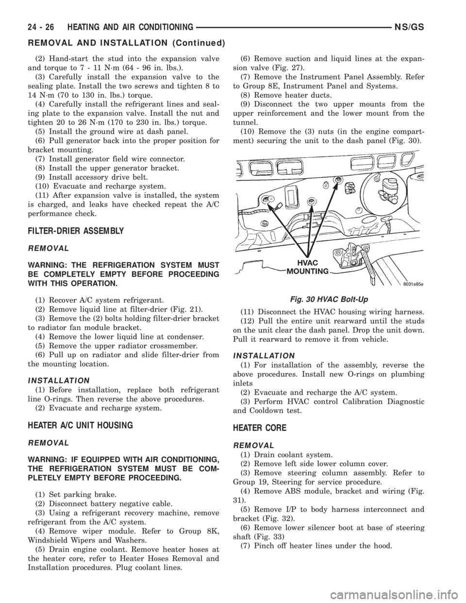
ment) securing the unit to the dash panel (Fig. 30).
(11) Disconnect the HVAC housing wiring harness.
(12) Pull the entire unit rearward until the studs
on the unit clear the dash panel. Drop the unit down.
Pull it rearward to remove it from vehicle.
INSTALLATION
(1) For installation of the assembly, reverse the
above procedures. Install new O-rings on plumbing
inlets
(2) Evacuate and recharge the A/C system.
(3) Perform HVAC control Calibration Diagnostic
and Cooldown test.
HEATER CORE
REMOVAL
(1) Drain coolant system.
(2) Remove left side lower column cover.
(3) Remove steering column assembly. Refer to
Group 19, Steering for service procedure.
(4) Remove ABS module, bracket and wiring (Fig.
31).
(5) Remove I/P to body harness interconnect and
bracket (Fig. 32).
(6) Remove lower silencer boot at base of steering
shaft (Fig. 33)
(7) Pinch off heater lines under the hood.
Fig. 30 HVAC Bolt-Up
24 - 26 HEATING AND AIR CONDITIONINGNS/GS
REMOVAL AND INSTALLATION (Continued)
Page 1894 of 1938

INSTALLATION
For installation, reverse the above procedures.
Install screws to retain heater core in housing.
Replace heater core tube inlet O-rings. Tighten
heater core tube retaining plate to 361 N´m (276
9 in. lbs.) torque.
HEATER HOSES
REMOVAL
NOTE: Review Safety Precautions and Warnings
before proceeding with this operation.
(1) Drain engine cooling system. Refer to Group 7,
Engine Cooling.
(2) Loosen clamps at each end of heater hose to be
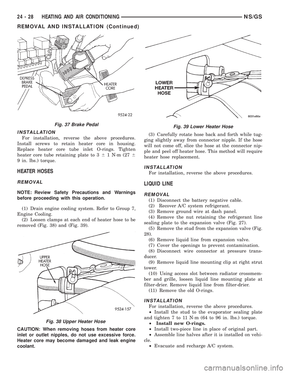
removed (Fig. 38) and (Fig. 39).
CAUTION: When removing hoses from heater core
inlet or outlet nipples, do not use excessive force.
Heater core may become damaged and leak engine
coolant.(3) Carefully rotate hose back and forth while tug-
ging slightly away from connector nipple. If the hose
will not come off, slice the hose at the connector nip-
ple and peel off heater hose. This method will require
heater hose replacement.
INSTALLATION
For installation, reverse the above procedures.
LIQUID LINE
REMOVAL
(1) Disconnect the battery negative cable.
(2) Recover A/C system refrigerant.
(3) Remove ground wire at dash panel.
(4) Remove the nut retaining the refrigerant line
sealing plate to the expansion valve (Fig. 27).
(5) Remove the stud from the expansion valve (Fig.
28).
(6) Remove liquid line from expansion valve.
(7) Cover the openings to prevent contamination.
(8) Disconnect wire connector at pressure trans-
ducer.
(9) Remove liquid line mounting clip at right strut
tower.
(10) Using access slot between radiator crossmem-
ber and grille, loosen liquid line mounting plate at
filter-drier. Remove liquid line from filter-drier.
(11) Remove the old O-rings.
INSTALLATION
For installation, reverse the above procedures.
²Install the stud to the evaporator sealing plate
and tighten 7 to 11 N´m (64 to 96 in. lbs.) torque.
²Install new O-rings.
²Install two-piece line in place of original part.
²Assemble line halves after it is installed on vehi-
cle.
²Evacuate and recharge A/C system.
Fig. 37 Brake Pedal
Fig. 38 Upper Heater Hose
Fig. 39 Lower Heater Hose
24 - 28 HEATING AND AIR CONDITIONINGNS/GS
REMOVAL AND INSTALLATION (Continued)
Page 1906 of 1938

cranking. Whenever the Powertrain Control Module
(PCM) sets a Diagnostic Trouble Code (DTC) that
affects vehicle emissions, it illuminates the MIL. If a
problem is detected, the PCM sends a message over
the CCD Bus to the instrument cluster to illuminate
the lamp. The PCM illuminates the MIL only for
DTC's that affect vehicle emissions. The MIL stays
on continuously when the PCM has entered a
Limp-In mode or identified a failed emission compo-
nent or system. The MIL remains on until the DTC
is erased. Refer to the Diagnostic Trouble Code
charts in this group for emission related codes.
Also, the MIL either flashes or illuminates contin-
uously when the PCM detects active engine misfire.
Refer to Misfire Monitoring in this section.
Additionally, the PCM may reset (turn off) the MIL
when one of the following occur:
²PCM does not detect the malfunction for 3 con-
secutive trips (except misfire and fuel system moni-
tors).
²PCM does not detect a malfunction while per-
forming three successive engine misfire or fuel sys-
tem tests. The PCM performs these tests while the
engine is operating within6375 RPM of and within
10 % of the load of the operating condition at which
the malfunction was first detected.
STATE DISPLAY TEST MODE
The switch inputs to the Powertrain Control Mod-
ule (PCM) have two recognized states; HIGH and
LOW. For this reason, the PCM cannot recognize the
difference between a selected switch position versus
an open circuit, a short circuit, or a defective switch.
If the State Display screen shows the change from
HIGH to LOW or LOW to HIGH, assume the entire
switch circuit to the PCM functions properly. From
the state display screen, access either State Display
Inputs and Outputs or State Display Sensors.
STATE DISPLAY INPUTS AND OUTPUTS
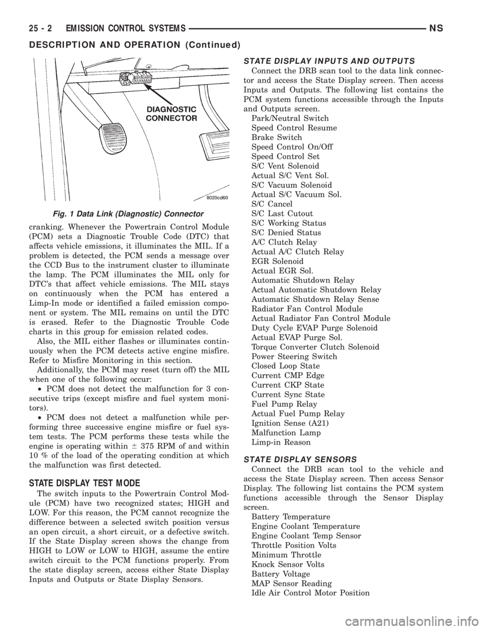
Connect the DRB scan tool to the data link connec-
tor and access the State Display screen. Then access
Inputs and Outputs. The following list contains the
PCM system functions accessible through the Inputs
and Outputs screen.
Park/Neutral Switch
Speed Control Resume
Brake Switch
Speed Control On/Off
Speed Control Set
S/C Vent Solenoid
Actual S/C Vent Sol.
S/C Vacuum Solenoid
Actual S/C Vacuum Sol.
S/C Cancel
S/C Last Cutout
S/C Working Status
S/C Denied Status
A/C Clutch Relay
Actual A/C Clutch Relay
EGR Solenoid
Actual EGR Sol.
Automatic Shutdown Relay
Actual Automatic Shutdown Relay
Automatic Shutdown Relay Sense
Radiator Fan Control Module
Actual Radiator Fan Control Module
Duty Cycle EVAP Purge Solenoid
Actual EVAP Purge Sol.
Torque Converter Clutch Solenoid
Power Steering Switch
Closed Loop State
Current CMP Edge
Current CKP State
Current Sync State
Fuel Pump Relay
Actual Fuel Pump Relay
Ignition Sense (A21)
Malfunction Lamp
Limp-in Reason
STATE DISPLAY SENSORS
Connect the DRB scan tool to the vehicle and
access the State Display screen. Then access Sensor
Display. The following list contains the PCM system
functions accessible through the Sensor Display
screen.
Battery Temperature
Engine Coolant Temperature
Engine Coolant Temp Sensor
Throttle Position Volts
Minimum Throttle
Knock Sensor Volts
Battery Voltage
MAP Sensor Reading
Idle Air Control Motor Position
Fig. 1 Data Link (Diagnostic) Connector
25 - 2 EMISSION CONTROL SYSTEMSNS
DESCRIPTION AND OPERATION (Continued)
Page 1908 of 1938

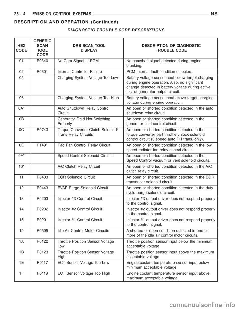
DIAGNOSTIC TROUBLE CODE DESCRIPTIONS
HEX
CODEGENERIC
SCAN
TOOL
CODEDRB SCAN TOOL
DISPLAYDESCRIPTION OF DIAGNOSTIC
TROUBLE CODE
01 P0340 No Cam Signal at PCM No camshaft signal detected during engine
cranking.
02 P0601 Internal Controller Failure PCM Internal fault condition detected.
05 Charging System Voltage Too Low Battery voltage sense input below target charging
during engine operation. Also, no significant
change detected in battery voltage during active
test of generator output circuit.
06 Charging System Voltage Too High Battery voltage sense input above target charging
voltage during engine operation.
0A* Auto Shutdown Relay Control
CircuitAn open or shorted condition detected in the auto
shutdown relay circuit.
0B Generator Field Not Switching
ProperlyAn open or shorted condition detected in the
generator field control circuit.
0C P0743 Torque Converter Clutch Soleniod/
Trans Relay CircuitsAn open or shorted condition detected in the
torque converter part throttle unlock solenoid
control circuit (3 speed auto RH trans. only).
0E P1491 Rad Fan Control Relay Circuit An open or shorted condition detected in the low
speed radiator fan relay control circuit.
0F* Speed Control Solenoid Circuits An open or shorted condition detected in the
Speed Control vacuum or vent solenoid circuits.
10* A/C Clutch Relay Circuit An open or shorted condition detected in the A/C
clutch relay circuit.
11 P0403 EGR Solenoid Circuit An open or shorted condition detected in the EGR
transducer solenoid circuit.
12 P0443 EVAP Purge Solenoid Circuit An open or shorted condition detected in the duty
cycle purge solenoid circuit.
13 P0203 Injector #3 Control Circuit Injector #3 output driver does not respond properly
to the control signal.
14 P0202 Injector #2 Control Circuit Injector #2 output driver does not respond properly
to the control signal.
15 P0201 Injector #1 Control Circuit Injector #1 output driver does not respond properly
to the control signal.
19 P0505 Idle Air Control Motor Circuits A shorted or open condition detected in one or
more of the idle air control motor circuits.
1A P0122 Throttle Position Sensor Voltage
LowThrottle position sensor input below the minimum
acceptable voltage
1B P0123 Throttle Position Sensor Voltage
HighThrottle position sensor input above the maximum
acceptable voltage.
1E P0117 ECT Sensor Voltage Too Low Engine coolant temperature sensor input below
minimum acceptable voltage.
1F P0118 ECT Sensor Voltage Too High Engine coolant temperature sensor input above
maximum acceptable voltage.
25 - 4 EMISSION CONTROL SYSTEMSNS
DESCRIPTION AND OPERATION (Continued)