radiator CHRYSLER VOYAGER 1996 Manual PDF
[x] Cancel search | Manufacturer: CHRYSLER, Model Year: 1996, Model line: VOYAGER, Model: CHRYSLER VOYAGER 1996Pages: 1938, PDF Size: 55.84 MB
Page 1119 of 1938
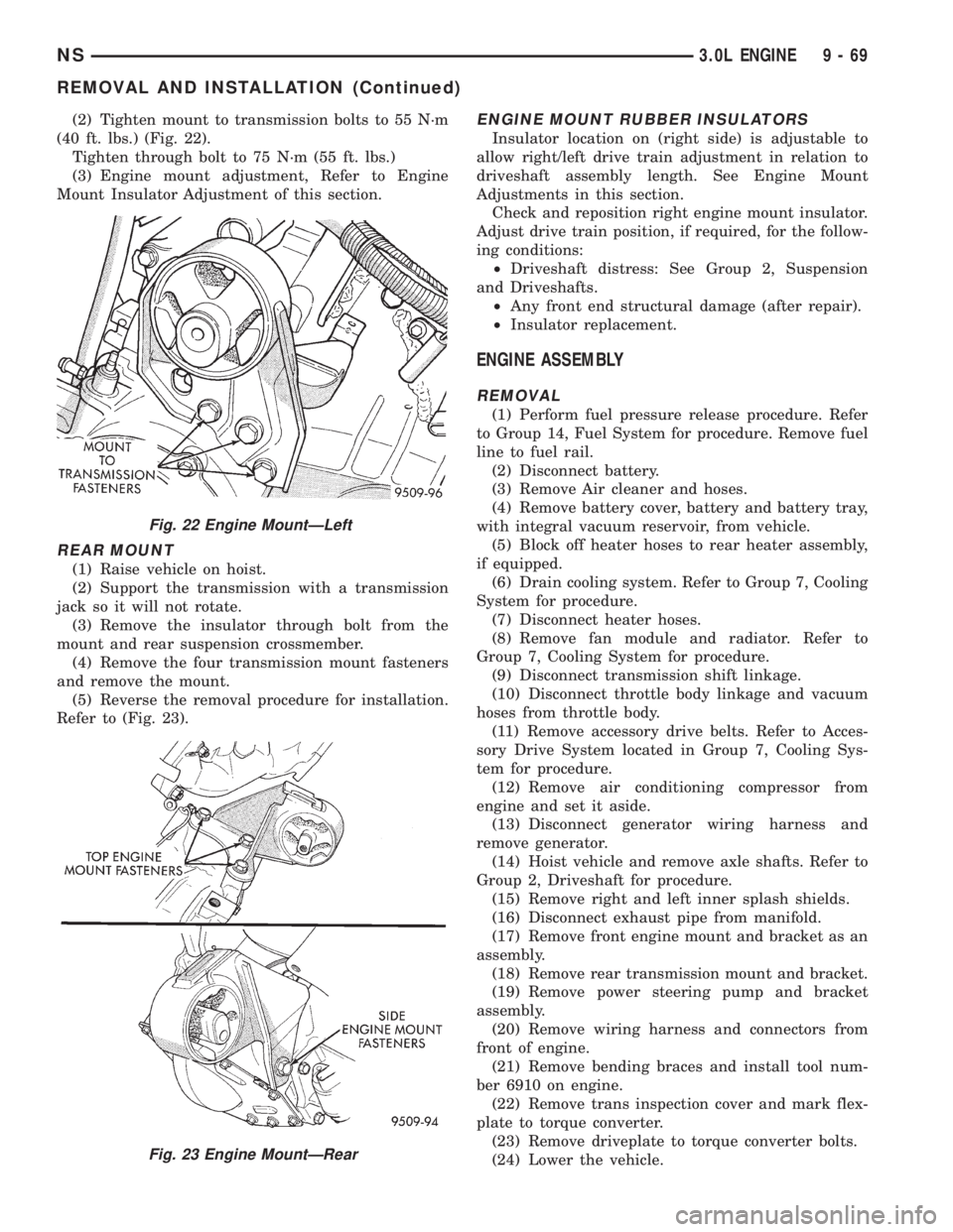
(2) Tighten mount to transmission bolts to 55 N´m
(40 ft. lbs.) (Fig. 22).
Tighten through bolt to 75 N´m (55 ft. lbs.)
(3) Engine mount adjustment, Refer to Engine
Mount Insulator Adjustment of this section.
REAR MOUNT
(1) Raise vehicle on hoist.
(2) Support the transmission with a transmission
jack so it will not rotate.
(3) Remove the insulator through bolt from the
mount and rear suspension crossmember.
(4) Remove the four transmission mount fasteners
and remove the mount.
(5) Reverse the removal procedure for installation.
Refer to (Fig. 23).
ENGINE MOUNT RUBBER INSULATORS
Insulator location on (right side) is adjustable to
allow right/left drive train adjustment in relation to
driveshaft assembly length. See Engine Mount
Adjustments in this section.
Check and reposition right engine mount insulator.
Adjust drive train position, if required, for the follow-
ing conditions:
²Driveshaft distress: See Group 2, Suspension
and Driveshafts.
²Any front end structural damage (after repair).
²Insulator replacement.
ENGINE ASSEMBLY
REMOVAL
(1) Perform fuel pressure release procedure. Refer
to Group 14, Fuel System for procedure. Remove fuel
line to fuel rail.
(2) Disconnect battery.
(3) Remove Air cleaner and hoses.
(4) Remove battery cover, battery and battery tray,
with integral vacuum reservoir, from vehicle.
(5) Block off heater hoses to rear heater assembly,
if equipped.
(6) Drain cooling system. Refer to Group 7, Cooling
System for procedure.
(7) Disconnect heater hoses.
(8) Remove fan module and radiator. Refer to
Group 7, Cooling System for procedure.
(9) Disconnect transmission shift linkage.
(10) Disconnect throttle body linkage and vacuum
hoses from throttle body.
(11) Remove accessory drive belts. Refer to Acces-
sory Drive System located in Group 7, Cooling Sys-
tem for procedure.
(12) Remove air conditioning compressor from
engine and set it aside.
(13) Disconnect generator wiring harness and
remove generator.
(14) Hoist vehicle and remove axle shafts. Refer to
Group 2, Driveshaft for procedure.
(15) Remove right and left inner splash shields.
(16) Disconnect exhaust pipe from manifold.
(17) Remove front engine mount and bracket as an
assembly.
(18) Remove rear transmission mount and bracket.
(19) Remove power steering pump and bracket
assembly.
(20) Remove wiring harness and connectors from
front of engine.
(21) Remove bending braces and install tool num-
ber 6910 on engine.
(22) Remove trans inspection cover and mark flex-
plate to torque converter.
(23) Remove driveplate to torque converter bolts.
(24) Lower the vehicle.
Fig. 22 Engine MountÐLeft
Fig. 23 Engine MountÐRear
NS3.0L ENGINE 9 - 69
REMOVAL AND INSTALLATION (Continued)
Page 1120 of 1938
(25) Remove ground straps to body.
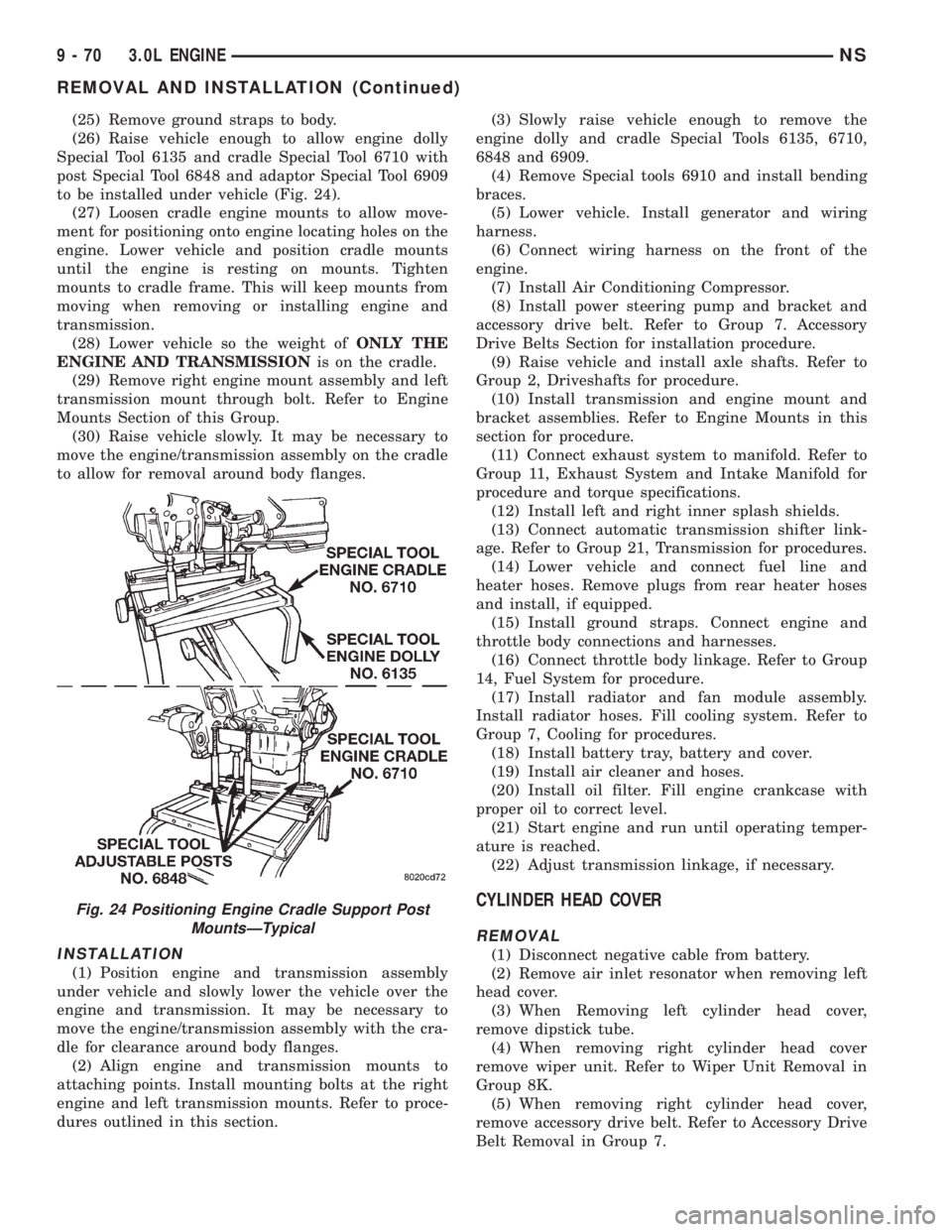
(26) Raise vehicle enough to allow engine dolly
Special Tool 6135 and cradle Special Tool 6710 with
post Special Tool 6848 and adaptor Special Tool 6909
to be installed under vehicle (Fig. 24).
(27) Loosen cradle engine mounts to allow move-
ment for positioning onto engine locating holes on the
engine. Lower vehicle and position cradle mounts
until the engine is resting on mounts. Tighten
mounts to cradle frame. This will keep mounts from
moving when removing or installing engine and
transmission.
(28) Lower vehicle so the weight ofONLY THE
ENGINE AND TRANSMISSIONis on the cradle.
(29) Remove right engine mount assembly and left
transmission mount through bolt. Refer to Engine
Mounts Section of this Group.
(30) Raise vehicle slowly. It may be necessary to
move the engine/transmission assembly on the cradle
to allow for removal around body flanges.
INSTALLATION
(1) Position engine and transmission assembly
under vehicle and slowly lower the vehicle over the
engine and transmission. It may be necessary to
move the engine/transmission assembly with the cra-
dle for clearance around body flanges.
(2) Align engine and transmission mounts to
attaching points. Install mounting bolts at the right
engine and left transmission mounts. Refer to proce-
dures outlined in this section.(3) Slowly raise vehicle enough to remove the
engine dolly and cradle Special Tools 6135, 6710,
6848 and 6909.
(4) Remove Special tools 6910 and install bending
braces.
(5) Lower vehicle. Install generator and wiring
harness.
(6) Connect wiring harness on the front of the
engine.
(7) Install Air Conditioning Compressor.
(8) Install power steering pump and bracket and
accessory drive belt. Refer to Group 7. Accessory
Drive Belts Section for installation procedure.
(9) Raise vehicle and install axle shafts. Refer to
Group 2, Driveshafts for procedure.
(10) Install transmission and engine mount and
bracket assemblies. Refer to Engine Mounts in this
section for procedure.
(11) Connect exhaust system to manifold. Refer to
Group 11, Exhaust System and Intake Manifold for
procedure and torque specifications.
(12) Install left and right inner splash shields.
(13) Connect automatic transmission shifter link-
age. Refer to Group 21, Transmission for procedures.
(14) Lower vehicle and connect fuel line and
heater hoses. Remove plugs from rear heater hoses
and install, if equipped.
(15) Install ground straps. Connect engine and
throttle body connections and harnesses.
(16) Connect throttle body linkage. Refer to Group
14, Fuel System for procedure.
(17) Install radiator and fan module assembly.
Install radiator hoses. Fill cooling system. Refer to
Group 7, Cooling for procedures.
(18) Install battery tray, battery and cover.
(19) Install air cleaner and hoses.
(20) Install oil filter. Fill engine crankcase with
proper oil to correct level.
(21) Start engine and run until operating temper-
ature is reached.
(22) Adjust transmission linkage, if necessary.
CYLINDER HEAD COVER
REMOVAL
(1) Disconnect negative cable from battery.
(2) Remove air inlet resonator when removing left
head cover.
(3) When Removing left cylinder head cover,
remove dipstick tube.
(4) When removing right cylinder head cover
remove wiper unit. Refer to Wiper Unit Removal in
Group 8K.
(5) When removing right cylinder head cover,
remove accessory drive belt. Refer to Accessory Drive
Belt Removal in Group 7.
Fig. 24 Positioning Engine Cradle Support Post
MountsÐTypical
9 - 70 3.0L ENGINENS
REMOVAL AND INSTALLATION (Continued)
Page 1126 of 1938
CAMSHAFT SPROCKETS
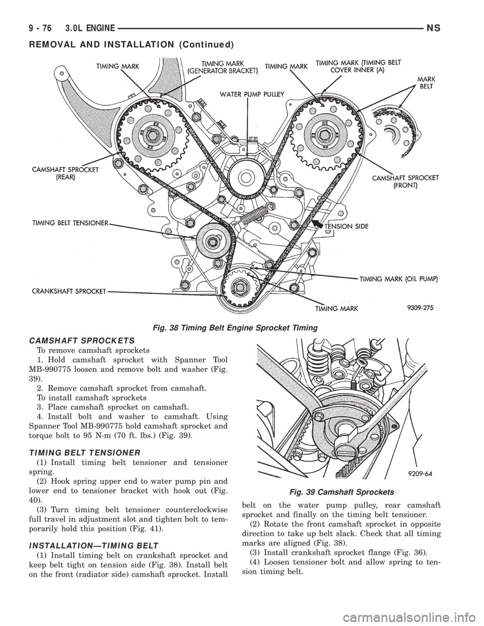
To remove camshaft sprockets
1. Hold camshaft sprocket with Spanner Tool
MB-990775 loosen and remove bolt and washer (Fig.
39).
2. Remove camshaft sprocket from camshaft.
To install camshaft sprockets
3. Place camshaft sprocket on camshaft.
4. Install bolt and washer to camshaft. Using
Spanner Tool MB-990775 hold camshaft sprocket and
torque bolt to 95 N´m (70 ft. lbs.) (Fig. 39).
TIMING BELT TENSIONER
(1) Install timing belt tensioner and tensioner
spring.
(2) Hook spring upper end to water pump pin and
lower end to tensioner bracket with hook out (Fig.
40).
(3) Turn timing belt tensioner counterclockwise
full travel in adjustment slot and tighten bolt to tem-
porarily hold this position (Fig. 41).
INSTALLATIONÐTIMING BELT
(1) Install timing belt on crankshaft sprocket and
keep belt tight on tension side (Fig. 38). Install belt
on the front (radiator side) camshaft sprocket. Installbelt on the water pump pulley, rear camshaft
sprocket and finally on the timing belt tensioner.
(2) Rotate the front camshaft sprocket in opposite
direction to take up belt slack. Check that all timing
marks are aligned (Fig. 38).
(3) Install crankshaft sprocket flange (Fig. 36).
(4) Loosen tensioner bolt and allow spring to ten-
sion timing belt.
Fig. 38 Timing Belt Engine Sprocket Timing
Fig. 39 Camshaft Sprockets
9 - 76 3.0L ENGINENS
REMOVAL AND INSTALLATION (Continued)
Page 1154 of 1938
ENGINE MOUNT RUBBER INSULATORS
Insulator location on (right side) is adjustable to
allow right/left drive train adjustment in relation to
drive shaft assembly length.
Check and reposition right engine mount insulator.
See Adjustments in this section. Adjust drive train
position, if required, for the following conditions:
a. Drive shaft distress. See Group 2, Suspension
and Driveshafts.
b. Any front end structural damage (after repair).
c. Insulator replacement.
ENGINE ASSEMBLY
REMOVAL
(1) Perform fuel pressure release procedure. Refer
to group 14 fuel system for procedure. Remove fuel
line to fuel rail.
(2) Disconnect battery.
(3) Remove air cleaner and hoses.
(4) Remove battery cover, battery and battery tray,
with integral vacuum reservoir, from vehicle.
(5) Block off heater hoses to rear heater assembly,
if equipped.
(6) Drain cooling system. Refer to Group 7, Cooling
System for procedure.
(7) Disconnect heater hoses.
(8) Remove fan module and radiator. Refer to
Group 7 Cooling System for procedure.
(9) Disconnect transmission shift linkage.
(10) Disconnect throttle body linkage and vacuum
hoses from throttle body.
(11) Remove accessory drive belts. Refer to Group
7, Accessory Drive Belts located in Cooling System
for procedure.
(12) Remove air conditioning compressor from
engine and set it aside.
(13) Disconnect generator wiring harness and
remove generator.
(14) Hoist vehicle and remove right and left inner
splash shields.
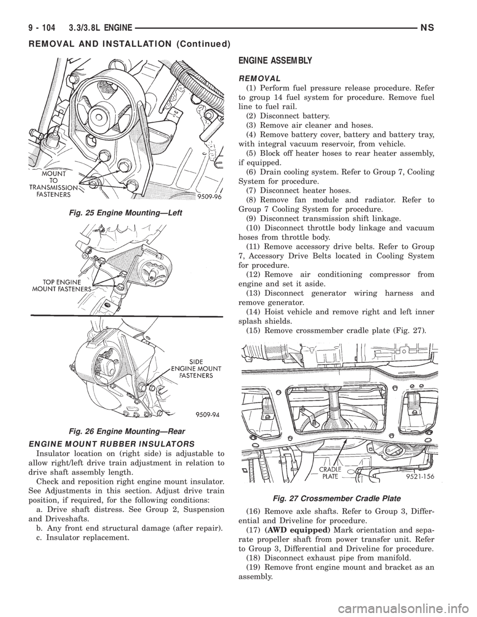
(15) Remove crossmember cradle plate (Fig. 27).
(16) Remove axle shafts. Refer to Group 3, Differ-
ential and Driveline for procedure.
(17)(AWD equipped)Mark orientation and sepa-
rate propeller shaft from power transfer unit. Refer
to Group 3, Differential and Driveline for procedure.
(18) Disconnect exhaust pipe from manifold.
(19) Remove front engine mount and bracket as an
assembly.
Fig. 25 Engine MountingÐLeft
Fig. 26 Engine MountingÐRear
Fig. 27 Crossmember Cradle Plate
9 - 104 3.3/3.8L ENGINENS
REMOVAL AND INSTALLATION (Continued)
Page 1155 of 1938
(20) Remove rear transmission mount and bracket.
(21) Remove power steering pump and bracket
assembly.
(22) Remove wiring harness and connectors from
front of engine.
(23) Remove bending braces and install tool num-
ber 6912 on engine.
(24) Remove transmission inspection cover and
mark flexplate to torque converter.
(25) Remove driveplate to torque converter bolts.
(26) Lower the vehicle.
(27) Remove ground straps to body.
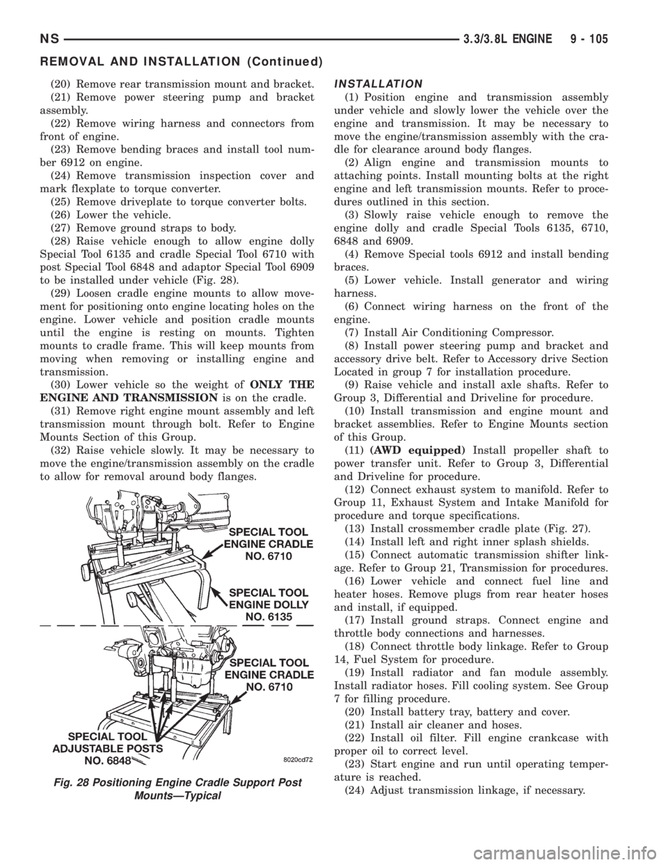
(28) Raise vehicle enough to allow engine dolly
Special Tool 6135 and cradle Special Tool 6710 with
post Special Tool 6848 and adaptor Special Tool 6909
to be installed under vehicle (Fig. 28).
(29) Loosen cradle engine mounts to allow move-
ment for positioning onto engine locating holes on the
engine. Lower vehicle and position cradle mounts
until the engine is resting on mounts. Tighten
mounts to cradle frame. This will keep mounts from
moving when removing or installing engine and
transmission.
(30) Lower vehicle so the weight ofONLY THE
ENGINE AND TRANSMISSIONis on the cradle.
(31) Remove right engine mount assembly and left
transmission mount through bolt. Refer to Engine
Mounts Section of this Group.
(32) Raise vehicle slowly. It may be necessary to
move the engine/transmission assembly on the cradle
to allow for removal around body flanges.INSTALLATION
(1) Position engine and transmission assembly
under vehicle and slowly lower the vehicle over the
engine and transmission. It may be necessary to
move the engine/transmission assembly with the cra-
dle for clearance around body flanges.
(2) Align engine and transmission mounts to
attaching points. Install mounting bolts at the right
engine and left transmission mounts. Refer to proce-
dures outlined in this section.
(3) Slowly raise vehicle enough to remove the
engine dolly and cradle Special Tools 6135, 6710,
6848 and 6909.
(4) Remove Special tools 6912 and install bending
braces.
(5) Lower vehicle. Install generator and wiring
harness.
(6) Connect wiring harness on the front of the
engine.
(7) Install Air Conditioning Compressor.
(8) Install power steering pump and bracket and
accessory drive belt. Refer to Accessory drive Section
Located in group 7 for installation procedure.
(9) Raise vehicle and install axle shafts. Refer to
Group 3, Differential and Driveline for procedure.
(10) Install transmission and engine mount and
bracket assemblies. Refer to Engine Mounts section
of this Group.
(11)(AWD equipped)Install propeller shaft to
power transfer unit. Refer to Group 3, Differential
and Driveline for procedure.
(12) Connect exhaust system to manifold. Refer to
Group 11, Exhaust System and Intake Manifold for
procedure and torque specifications.
(13) Install crossmember cradle plate (Fig. 27).
(14) Install left and right inner splash shields.
(15) Connect automatic transmission shifter link-
age. Refer to Group 21, Transmission for procedures.
(16) Lower vehicle and connect fuel line and
heater hoses. Remove plugs from rear heater hoses
and install, if equipped.
(17) Install ground straps. Connect engine and
throttle body connections and harnesses.
(18) Connect throttle body linkage. Refer to Group
14, Fuel System for procedure.
(19) Install radiator and fan module assembly.
Install radiator hoses. Fill cooling system. See Group
7 for filling procedure.
(20) Install battery tray, battery and cover.
(21) Install air cleaner and hoses.
(22) Install oil filter. Fill engine crankcase with
proper oil to correct level.
(23) Start engine and run until operating temper-
ature is reached.
(24) Adjust transmission linkage, if necessary.
Fig. 28 Positioning Engine Cradle Support Post
MountsÐTypical
NS3.3/3.8L ENGINE 9 - 105
REMOVAL AND INSTALLATION (Continued)
Page 1181 of 1938
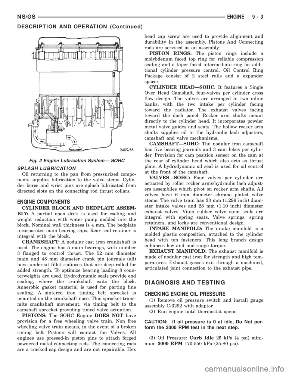
SPLASH LUBRICATION
Oil returning to the pan from pressurized compo-
nents supplies lubrication to the valve stems. Cylin-
der bores and wrist pins are splash lubricated from
directed slots on the connecting rod thrust collars.
ENGINE COMPONENTS
CYLINDER BLOCK AND BEDPLATE ASSEM-
B LY:A partial open deck is used for cooling and
weight reduction with water pump molded into the
block. Nominal wall thickness is 4 mm. The bedplate
incorporates main bearing caps. Rear seal retainer is
integral with the block.
CRANKSHAFT:A nodular cast iron crankshaft is
used. The engine has 5 main bearings, with number
3 flanged to control thrust. The 52 mm diameter
main and 48 mm diameter crank pin journals (all)
have undercut fillet radiuses that are deep rolled for
added strength. To optimize bearing loading 8 coun-
terweights are used. Hydrodynamic seals provide end
sealing, where the crankshaft exits the block.
Anaerobic gasket material is used for parting line
sealing. A sintered iron timing belt sprocket is
mounted on the crankshaft nose. This sprocket trans-
mits crankshaft movement, via timing belt to the
camshaft sprocket providing timed valve actuation.
PISTONS:The SOHC EngineDOES NOThave
provision for a free wheeling valve train. Non free
wheeling valve train means, in the event of a broken
timing belt Pistons will contact the Valves. All
engines use pressed-in piston pins to attach forged
powdered metal connecting rods. The connecting rods
are a cracked cap design and are not repairable. Hexhead cap screw are used to provide alignment and
durability in the assembly. Pistons And Connecting
rods are serviced as an assembly.
PISTON RINGS:The piston rings include a
molybdenum faced top ring for reliable compression
sealing and a taper faced intermediate ring for addi-
tional cylinder pressure control. Oil Control Ring
Package consist of 2 steel rails and a expander
spacer.
CYLINDER HEADÐSOHC:It features a Single
Over Head Camshaft, four-valves per cylinder cross
flow design. The valves are arranged in two inline
banks, with the two intake per cylinder facing
toward the radiator. The exhaust valves facing
toward the dash panel. Rocker arm shafts mount
directly to the cylinder head. It incorporates powder
metal valve guides and seats. The hollow rocker arm
shafts supplies oil to the hydraulic lash adjusters,
camshaft and valve mechanisms.
CAMSHAFTÐSOHC:The nodular iron camshaft
has five bearing journals and 3 cam lobes per cylin-
der. Provision for cam position sensor on the cam at
the rear of cylinder head which also acts as thrust
plate. A hydrodynamic oil seal is used for oil control
at the front of the camshaft.
VALVESÐSOHC:Four valves per cylinder are
actuated by roller rocker arms/hydraulic lash adjust-
ers assemblies which pivot on rocker arm shafts. All
valves have 6 mm diameter chrome plated valve
stems. The valve train has 33 mm (1.299 inch) diam-
eter intake valves and 28 mm (1.10 inch) diameter
exhaust valves. Viton rubber valve stem seals are
integral with spring seats. Valve springs, spring
retainers, and locks are conventional design.
INTAKE MANIFOLD:The intake manifold is a
molded plastic composition, attached to the cylinder
head with ten fasteners. This long branch design
enhances low and mid-range torque.
EXHAUST MANIFOLD:The exhaust manifold is
made of nodular cast iron for strength and high tem-
peratures. Exhaust gasses exit through a machined,
articulated joint connection to the exhaust pipe.
DIAGNOSIS AND TESTING
CHECKING ENGINE OIL PRESSURE
(1) Remove oil pressure switch and install gauge
assembly C-3292 with adaptor.
(2) Run engine until thermostat opens.
CAUTION: If oil pressure is 0 at idle, Do Not per-
form the 3000 RPM test in the next step.
(3) Oil Pressure:Curb Idle25 kPa (4 psi) mini-
mum3000 RPM170-550 kPa (25-80 psi).
Fig. 2 Engine Lubrication SystemÐ SOHC
NS/GSENGINE 9 - 3
DESCRIPTION AND OPERATION (Continued)
Page 1231 of 1938
ENGINE ASSEMBLY
REMOVAL
(1) Disconnect the battery.
(2) Remove the air cleaner assembly and inlet
hose.
(3) Remove both hoses at intercooler and engine.
(4) Disconnect EGR vacuum hose.
(5) Disconnect brake booster vacuum hose.
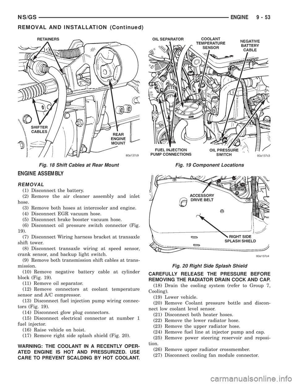
(6) Disconnect oil pressure switch connector (Fig.
19).
(7) Disconnect Wiring harness bracket at transaxle
shift tower.
(8) Disconnect transaxle wiring at speed sensor,
crank sensor, and backup light switch.
(9) Remove both transmission shift cables at trans-
mission.
(10) Remove negative battery cable at cylinder
block (Fig. 19).
(11) Remove oil separator.
(12) Remove connectors at coolant temperature
sensor and A/C compressor.
(13) Disconnect fuel injection pump wiring connec-
tors (Fig. 19).
(14) Disconnect glow plug connectors.
(15) Disconnect electrical connector at number 1
fuel injector.
(16) Raise vehicle on hoist.
(17) Remove right side splash shield (Fig. 20).
WARNING: THE COOLANT IN A RECENTLY OPER-
ATED ENGINE IS HOT AND PRESSURIZED. USE
CARE TO PREVENT SCALDING BY HOT COOLANT.CAREFULLY RELEASE THE PRESSURE BEFORE
REMOVING THE RADIATOR DRAIN COCK AND CAP.
(18) Drain the cooling system (refer to Group 7,
Cooling).
(19) Lower vehicle.
(20) Remove Coolant pressure bottle and discon-
nect low coolant level sensor.
(21) Disconnect both heater hoses.
(22) Remove the lower radiator hose.
(23) Remove the upper radiator hose.
(24) Remove fuel line at injector pump and cap.
(25) Remove power steering reservoir and reposi-
tion.
(26) Remove upper radiator crossmember.
(27) Disconnect cooling fan module connector.
Fig. 18 Shift Cables at Rear MountFig. 19 Component Locations
Fig. 20 Right Side Splash Shield
NS/GSENGINE 9 - 53
REMOVAL AND INSTALLATION (Continued)
Page 1232 of 1938
(28) Remove radiator support bolts.It is neces-
sary to loosen the receiver/dryer to gain access
to the radiator bolts.
(29) Remove radiator and fans as an assembly.
(30) Remove accessory drive belt generator/power
steering. Refer to Group 7, for procedure.
(31) Remove both power steering lines at pump,
and cap both lines.
NOTE: It is not necessary to discharge A/C system
for engine removal.
(32) Remove A/C compressor. Secure compressor
away from engine for clearance during engine
removal.
(33) Remove Generator and adjusting bracket.
NOTE: Do not remove the mounting base from the
generator. It is aligned at the factory and cannot be
realigned in the field.
(34) Hoist vehicle.
(35) Remove exhaust pipe at turbo outlet.
(36) Remove connections at starter.
(37) Remove power steering high pressure line
bracket at rear of oil pan.
(38) Remove both driveshafts from transaxle. Refer
to Group 2, Suspension and Driveshafts.
(39) Disconnect clutch cable at transaxle.
(40) Remove reinforcement plate on lower cross-
member.
(41) Remove front and rear engine mounts. Refer
to procedure outlined in this section.
(42) Drain engine oil and remove oil filter if neces-
sary.
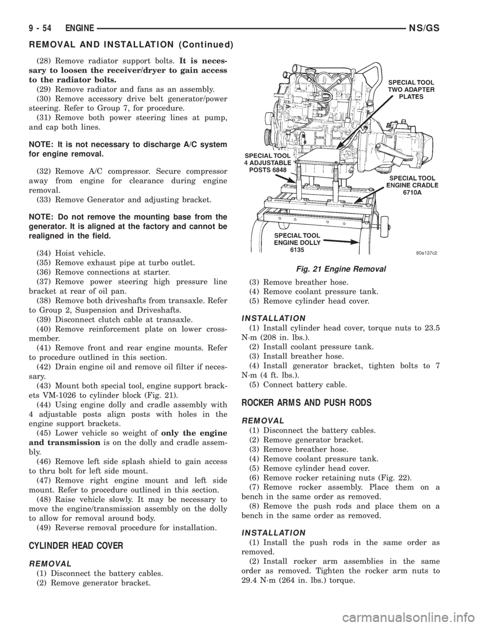
(43) Mount both special tool, engine support brack-
ets VM-1026 to cylinder block (Fig. 21).
(44) Using engine dolly and cradle assembly with
4 adjustable posts align posts with holes in the
engine support brackets.
(45) Lower vehicle so weight ofonly the engine
and transmissionis on the dolly and cradle assem-
bly.
(46) Remove left side splash shield to gain access
to thru bolt for left side mount.
(47) Remove right engine mount and left side
mount. Refer to procedure outlined in this section.
(48) Raise vehicle slowly. It may be necessary to
move the engine/transmission assembly on the dolly
to allow for removal around body.
(49) Reverse removal procedure for installation.
CYLINDER HEAD COVER
REMOVAL
(1) Disconnect the battery cables.
(2) Remove generator bracket.(3) Remove breather hose.
(4) Remove coolant pressure tank.
(5) Remove cylinder head cover.
INSTALLATION
(1) Install cylinder head cover, torque nuts to 23.5
N´m (208 in. lbs.).
(2) Install coolant pressure tank.
(3) Install breather hose.
(4) Install generator bracket, tighten bolts to 7
N´m (4 ft. lbs.).
(5) Connect battery cable.
ROCKER ARMS AND PUSH RODS
REMOVAL
(1) Disconnect the battery cables.
(2) Remove generator bracket.
(3) Remove breather hose.
(4) Remove coolant pressure tank.
(5) Remove cylinder head cover.
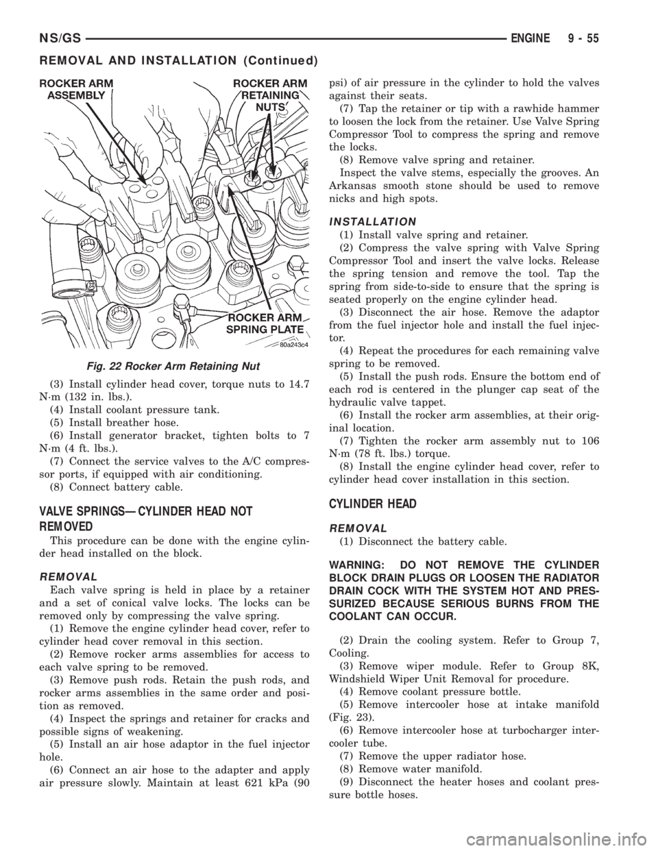
(6) Remove rocker retaining nuts (Fig. 22).
(7) Remove rocker assembly. Place them on a
bench in the same order as removed.
(8) Remove the push rods and place them on a
bench in the same order as removed.
INSTALLATION
(1) Install the push rods in the same order as
removed.
(2) Install rocker arm assemblies in the same
order as removed. Tighten the rocker arm nuts to
29.4 N´m (264 in. lbs.) torque.
Fig. 21 Engine Removal
9 - 54 ENGINENS/GS
REMOVAL AND INSTALLATION (Continued)
Page 1233 of 1938
(3) Install cylinder head cover, torque nuts to 14.7
N´m (132 in. lbs.).
(4) Install coolant pressure tank.
(5) Install breather hose.
(6) Install generator bracket, tighten bolts to 7
N´m (4 ft. lbs.).
(7) Connect the service valves to the A/C compres-
sor ports, if equipped with air conditioning.
(8) Connect battery cable.
VALVE SPRINGSÐCYLINDER HEAD NOT
REMOVED
This procedure can be done with the engine cylin-
der head installed on the block.
REMOVAL
Each valve spring is held in place by a retainer
and a set of conical valve locks. The locks can be
removed only by compressing the valve spring.
(1) Remove the engine cylinder head cover, refer to
cylinder head cover removal in this section.
(2) Remove rocker arms assemblies for access to
each valve spring to be removed.
(3) Remove push rods. Retain the push rods, and
rocker arms assemblies in the same order and posi-
tion as removed.
(4) Inspect the springs and retainer for cracks and
possible signs of weakening.
(5) Install an air hose adaptor in the fuel injector
hole.
(6) Connect an air hose to the adapter and apply
air pressure slowly. Maintain at least 621 kPa (90psi) of air pressure in the cylinder to hold the valves
against their seats.
(7) Tap the retainer or tip with a rawhide hammer
to loosen the lock from the retainer. Use Valve Spring
Compressor Tool to compress the spring and remove
the locks.
(8) Remove valve spring and retainer.
Inspect the valve stems, especially the grooves. An
Arkansas smooth stone should be used to remove
nicks and high spots.
INSTALLATION
(1) Install valve spring and retainer.
(2) Compress the valve spring with Valve Spring
Compressor Tool and insert the valve locks. Release
the spring tension and remove the tool. Tap the
spring from side-to-side to ensure that the spring is
seated properly on the engine cylinder head.
(3) Disconnect the air hose. Remove the adaptor
from the fuel injector hole and install the fuel injec-
tor.
(4) Repeat the procedures for each remaining valve
spring to be removed.
(5) Install the push rods. Ensure the bottom end of
each rod is centered in the plunger cap seat of the
hydraulic valve tappet.
(6) Install the rocker arm assemblies, at their orig-
inal location.
(7) Tighten the rocker arm assembly nut to 106
N´m (78 ft. lbs.) torque.
(8) Install the engine cylinder head cover, refer to
cylinder head cover installation in this section.
CYLINDER HEAD
REMOVAL
(1) Disconnect the battery cable.
WARNING: DO NOT REMOVE THE CYLINDER
BLOCK DRAIN PLUGS OR LOOSEN THE RADIATOR
DRAIN COCK WITH THE SYSTEM HOT AND PRES-
SURIZED BECAUSE SERIOUS BURNS FROM THE
COOLANT CAN OCCUR.
(2) Drain the cooling system. Refer to Group 7,
Cooling.
(3) Remove wiper module. Refer to Group 8K,
Windshield Wiper Unit Removal for procedure.
(4) Remove coolant pressure bottle.
(5) Remove intercooler hose at intake manifold
(Fig. 23).
(6) Remove intercooler hose at turbocharger inter-
cooler tube.
(7) Remove the upper radiator hose.
(8) Remove water manifold.
(9) Disconnect the heater hoses and coolant pres-
sure bottle hoses.
Fig. 22 Rocker Arm Retaining Nut
NS/GSENGINE 9 - 55
REMOVAL AND INSTALLATION (Continued)
Page 1237 of 1938
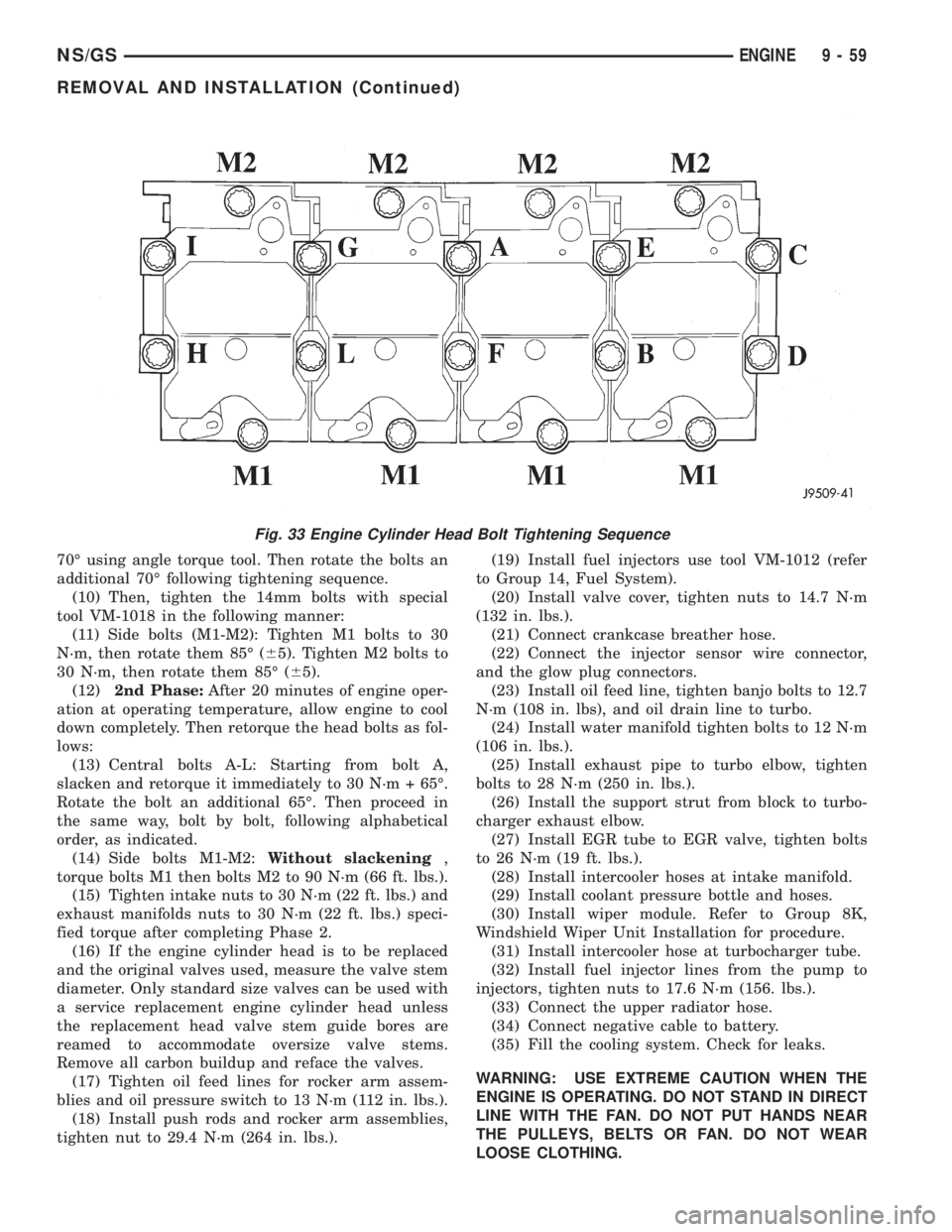
70É using angle torque tool. Then rotate the bolts an
additional 70É following tightening sequence.
(10) Then, tighten the 14mm bolts with special
tool VM-1018 in the following manner:
(11) Side bolts (M1-M2): Tighten M1 bolts to 30
N´m, then rotate them 85É (65). Tighten M2 bolts to
30 N´m, then rotate them 85É (65).
(12)2nd Phase:After 20 minutes of engine oper-
ation at operating temperature, allow engine to cool
down completely. Then retorque the head bolts as fol-
lows:
(13) Central bolts A-L: Starting from bolt A,
slacken and retorque it immediately to 30 N´m + 65É.
Rotate the bolt an additional 65É. Then proceed in
the same way, bolt by bolt, following alphabetical
order, as indicated.
(14) Side bolts M1-M2:Without slackening,
torque bolts M1 then bolts M2 to 90 N´m (66 ft. lbs.).
(15) Tighten intake nuts to 30 N´m (22 ft. lbs.) and
exhaust manifolds nuts to 30 N´m (22 ft. lbs.) speci-
fied torque after completing Phase 2.
(16) If the engine cylinder head is to be replaced
and the original valves used, measure the valve stem
diameter. Only standard size valves can be used with
a service replacement engine cylinder head unless
the replacement head valve stem guide bores are
reamed to accommodate oversize valve stems.
Remove all carbon buildup and reface the valves.
(17) Tighten oil feed lines for rocker arm assem-
blies and oil pressure switch to 13 N´m (112 in. lbs.).
(18) Install push rods and rocker arm assemblies,
tighten nut to 29.4 N´m (264 in. lbs.).(19) Install fuel injectors use tool VM-1012 (refer
to Group 14, Fuel System).
(20) Install valve cover, tighten nuts to 14.7 N´m
(132 in. lbs.).
(21) Connect crankcase breather hose.
(22) Connect the injector sensor wire connector,
and the glow plug connectors.
(23) Install oil feed line, tighten banjo bolts to 12.7
N´m (108 in. lbs), and oil drain line to turbo.
(24) Install water manifold tighten bolts to 12 N´m
(106 in. lbs.).
(25) Install exhaust pipe to turbo elbow, tighten
bolts to 28 N´m (250 in. lbs.).
(26) Install the support strut from block to turbo-
charger exhaust elbow.
(27) Install EGR tube to EGR valve, tighten bolts
to 26 N´m (19 ft. lbs.).
(28) Install intercooler hoses at intake manifold.
(29) Install coolant pressure bottle and hoses.
(30) Install wiper module. Refer to Group 8K,
Windshield Wiper Unit Installation for procedure.
(31) Install intercooler hose at turbocharger tube.
(32) Install fuel injector lines from the pump to
injectors, tighten nuts to 17.6 N´m (156. lbs.).
(33) Connect the upper radiator hose.
(34) Connect negative cable to battery.
(35) Fill the cooling system. Check for leaks.
WARNING: USE EXTREME CAUTION WHEN THE
ENGINE IS OPERATING. DO NOT STAND IN DIRECT
LINE WITH THE FAN. DO NOT PUT HANDS NEAR
THE PULLEYS, BELTS OR FAN. DO NOT WEAR
LOOSE CLOTHING.
Fig. 33 Engine Cylinder Head Bolt Tightening Sequence
NS/GSENGINE 9 - 59
REMOVAL AND INSTALLATION (Continued)