radiator CHRYSLER VOYAGER 1996 Owners Manual
[x] Cancel search | Manufacturer: CHRYSLER, Model Year: 1996, Model line: VOYAGER, Model: CHRYSLER VOYAGER 1996Pages: 1938, PDF Size: 55.84 MB
Page 1400 of 1938
FUEL INJECTION SYSTEMÐ2.0L ENGINE
INDEX
page page
GENERAL INFORMATION
INTRODUCTIONÐ2.0L ENGINE............ 32
MODES OF OPERATIONÐ2.0L ENGINE..... 32
DESCRIPTION AND OPERATION
AIR CONDITIONING (A/C) RELAYÐPCM
OUTPUTÐ2.0L ENGINE................ 35
AIR CONDITIONING PRESSURE
TRANSDUCERÐPCM INPUTÐ
2.0L ENGINE......................... 33
AIR CONDITIONING SWITCH SENSEÐ
PCM INPUTÐ2.0L ENGINE.............. 33
AUTOMATIC SHUTDOWN (ASD) SENSEÐ
PCM INPUTÐ2.0L ENGINE.............. 33
AUTOMATIC SHUTDOWN RELAYÐ
PCM OUTPUTÐ2.0L ENGINE............ 35
BATTERY VOLTAGEÐPCM INPUTÐ
2.0L ENGINE......................... 33
CAMSHAFT POSITION SENSORÐ
PCM INPUTÐ2.0L ENGINE.............. 33
CRANKSHAFT POSITION SENSORÐ
PCM INPUTÐ2.0L ENGINE.............. 33
DATA LINK CONNECTORÐPCM OUTPUTÐ
2.0L ENGINE......................... 35
ELECTRONIC EGR TRANSDUCERÐ
PCM OUTPUTÐ2.0L ENGINE............ 35
ENGINE COOLANT TEMPERATURE SENSORÐ
PCM INPUTÐ2.0L ENGINE.............. 33
FUEL INJECTORSÐPCM OUTPUTÐ
2.0L ENGINE......................... 35
FUEL PUMP RELAYÐPCM OUTPUTÐ
2.0L ENGINE......................... 35
GENERATOR FIELDÐPCM OUTPUTÐ
2.0L ENGINE......................... 35
HEATED OXYGEN SENSORÐPCM INPUTÐ
2.0L ENGINE......................... 33
IDLE AIR CONTROL MOTORÐPCM OUTPUTÐ
2.0L ENGINE......................... 35
IGNITION COILÐPCM OUTPUTÐ
2.0L ENGINE......................... 36KNOCK SENSORÐPCM INPUTÐ
2.0L ENGINE......................... 34
MALFUNCTION INDICATOR (CHECK ENGINE)
LAMPÐPCM OUTPUTÐ2.0L ENGINE...... 36
MANIFOLD ABSOLUTE PRESSURE
(MAP SENSOR)ÐPCM INPUTÐ
2.0L ENGINE......................... 34
POWERTRAIN CONTROL MODULEÐ
2.0L ENGINE......................... 33
RADIATOR FAN CONTROL MODULEÐ
PCM OUTPUTÐ2.0L ENGINE............ 36
SPEED CONTROL SOLENOIDSÐ
PCM OUTPUTÐ2.0L ENGINE............ 36
SPEED CONTROLÐPCM INPUTÐ
2.0L ENGINE......................... 34
STARTER RELAYÐPCM OUTPUTÐ
2.0L ENGINE......................... 35
SYSTEM DIAGNOSISÐ2.0L ENGINE........ 33
TACHOMETERÐPCM OUTPUTÐ
2.0L ENGINE......................... 36
THROTTLE BODYÐ2.0L ENGINE.......... 36
THROTTLE POSITION SENSOR/ IDLE AIR
CONTROL MOTORÐPCM INPUTÐ
2.0L ENGINE......................... 35
DIAGNOSIS AND TESTING
ASD AND FUEL PUMP RELAYSÐ
2.0L ENGINE......................... 39
CAMSHAFT AND CRANKSHAFT
POSITION SENSOR................... 40
ENGINE COOLANT TEMPERATURE
SENSOR............................ 40
KNOCK SENSORÐ2.0L ENGINE........... 40
MANIFOLD ABSOLUTE PRESSURE
(MAP) SENSORÐ2.0L ENGINE........... 39
THROTTLE BODY MINIMUM AIR FLOW..... 41
THROTTLE POSITION SENSOR........... 40
VISUAL INSPECTIONÐSOHC............. 36
SPECIFICATIONS
TORQUE............................. 42
GENERAL INFORMATION
INTRODUCTIONÐ2.0L ENGINE
Refer to the Introduction for 2.4/3.0/3.3/3.8L
engines under General Information in the Fuel Injec-
tion System section of group 14 for more information.
MODES OF OPERATIONÐ2.0L ENGINE
Refer to the Modes of Operation for 2.4/3.0/3.3/3.8L
engines under General Information in the Fuel Injec-
tion System section of group 14 for more information.
14 - 32 FUEL SYSTEMÐ2.5L DIESEL ENGINE/2.0L GAS ENGINENS/GS
Page 1404 of 1938
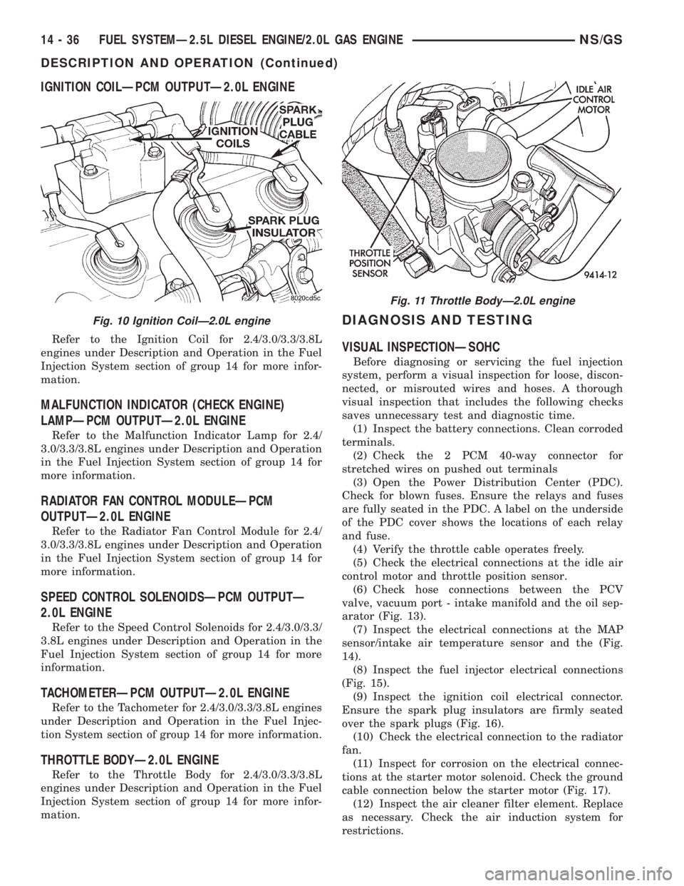
IGNITION COILÐPCM OUTPUTÐ2.0L ENGINE
Refer to the Ignition Coil for 2.4/3.0/3.3/3.8L
engines under Description and Operation in the Fuel
Injection System section of group 14 for more infor-
mation.
MALFUNCTION INDICATOR (CHECK ENGINE)
LAMPÐPCM OUTPUTÐ2.0L ENGINE
Refer to the Malfunction Indicator Lamp for 2.4/
3.0/3.3/3.8L engines under Description and Operation
in the Fuel Injection System section of group 14 for
more information.
RADIATOR FAN CONTROL MODULEÐPCM
OUTPUTÐ2.0L ENGINE
Refer to the Radiator Fan Control Module for 2.4/
3.0/3.3/3.8L engines under Description and Operation
in the Fuel Injection System section of group 14 for
more information.
SPEED CONTROL SOLENOIDSÐPCM OUTPUTÐ
2.0L ENGINE
Refer to the Speed Control Solenoids for 2.4/3.0/3.3/
3.8L engines under Description and Operation in the
Fuel Injection System section of group 14 for more
information.
TACHOMETERÐPCM OUTPUTÐ2.0L ENGINE
Refer to the Tachometer for 2.4/3.0/3.3/3.8L engines
under Description and Operation in the Fuel Injec-
tion System section of group 14 for more information.
THROTTLE BODYÐ2.0L ENGINE
Refer to the Throttle Body for 2.4/3.0/3.3/3.8L
engines under Description and Operation in the Fuel
Injection System section of group 14 for more infor-
mation.
DIAGNOSIS AND TESTING
VISUAL INSPECTIONÐSOHC
Before diagnosing or servicing the fuel injection
system, perform a visual inspection for loose, discon-
nected, or misrouted wires and hoses. A thorough
visual inspection that includes the following checks
saves unnecessary test and diagnostic time.
(1) Inspect the battery connections. Clean corroded
terminals.
(2) Check the 2 PCM 40-way connector for
stretched wires on pushed out terminals
(3) Open the Power Distribution Center (PDC).
Check for blown fuses. Ensure the relays and fuses
are fully seated in the PDC. A label on the underside
of the PDC cover shows the locations of each relay
and fuse.
(4) Verify the throttle cable operates freely.
(5) Check the electrical connections at the idle air
control motor and throttle position sensor.
(6) Check hose connections between the PCV
valve, vacuum port - intake manifold and the oil sep-
arator (Fig. 13).
(7) Inspect the electrical connections at the MAP
sensor/intake air temperature sensor and the (Fig.
14).
(8) Inspect the fuel injector electrical connections
(Fig. 15).
(9) Inspect the ignition coil electrical connector.
Ensure the spark plug insulators are firmly seated
over the spark plugs (Fig. 16).
(10) Check the electrical connection to the radiator
fan.
(11) Inspect for corrosion on the electrical connec-
tions at the starter motor solenoid. Check the ground
cable connection below the starter motor (Fig. 17).
(12) Inspect the air cleaner filter element. Replace
as necessary. Check the air induction system for
restrictions.
Fig. 10 Ignition CoilÐ2.0L engine
Fig. 11 Throttle BodyÐ2.0L engine
14 - 36 FUEL SYSTEMÐ2.5L DIESEL ENGINE/2.0L GAS ENGINENS/GS
DESCRIPTION AND OPERATION (Continued)
Page 1476 of 1938
GENERAL INFORMATION
31TH TRANSAXLE
NOTE: Safety goggles should be worn at all times
when working on these transaxles.
This transaxle combines torque converter, three
speed transmission, final drive gearing, and differen-
tial into a front wheel drive system. The identifica-
tion markings and usage of the transaxle are charted
in Diagnosis and Tests.
NOTE: Transaxle operation requirements are differ-
ent for each vehicle and engine combination. Some
internal parts will be different to provide for this.
Therefore, when replacing parts, refer to the seven
digit part number stamped on rear of the transaxle
oil pan flange.
Within this transaxle, there are three primary
areas:
(1) Main center line plus valve body.
(2) Transfer shaft center line (includes governor
and parking sprag).
(3) Differential center line.
(4) Center distances between the main rotating
parts in these three areas are held precise to main-
tain a low noise level.
(5) The torque converter, transaxle area, and dif-
ferential are housed in an integral aluminum die
casting.The differential oil sump is common
with the transaxle sump. Separate filling of the
differential is NOT necessary.
(6) The torque converter is attached to the crank-
shaft through a flexible driving plate. Cooling of the
converter is accomplished by circulating the tran-
saxle fluid through a remote cooler. There are two
types of coolers used. An oil-to-water type cooler
located in the radiator side tank and/or an oil-to air
heat exchanger. The torque converter assembly is a
sealed unit that cannot be disassembled.
(7) The transaxle fluid is filtered by an internal fil-
ter attached to the lower side of the valve body
assembly.
(8) Engine torque is transmitted to the torque con-
verter then, through the input shaft to multiple-disc
clutches in the transaxle. The power flow depends on
the application of the clutches and bands. Refer to
Elements in Use Chart in Diagnosis and Tests sec-
tion.
(9) The transaxle consists of:
²Two multiple-disc clutches
²An overrunning clutch
²Two servos
²A hydraulic accumulator
²Two bands²Two planetary gear sets
This provides three forward ratios and a reverse
ratio. The common sun gear of the planetary gear
sets is connected to the front clutch by a driving
shell. The drive shell is splined to the sun gear and
front clutch retainer. The hydraulic system consists
of an oil pump, and a single valve body which con-
tains all of the valves except the governor valves.
The transaxle sump and differential sump are both
vented through the dipstick. Output torque from the
main center line is delivered through helical gears to
the transfer shaft. This gear set is a factor of the
final drive (axle) ratio. The shaft also carries the gov-
ernor and parking sprag. An integral helical gear on
the transfer shaft drives the differential ring gear.
The final drive gearing is completed with one of two
gear ratios of 2.98 or 3.19 depending on model and
application.
FLUID LEVEL AND CONDITION
NOTE: The transmission and differential sump have
a common oil sump with a communicating opening
between the two.
The torque converter fills in both the P Park and N
Neutral positions. Place the selector lever in P Park
to be sure that the fluid level check is accurate.The
engine should be running at idle speed for at
least one minute, with the vehicle on level
ground. This will assure complete oil level sta-
bilization between differential and transmis-
sion.The fluid should be at normal operating
temperature (approximately 82 C. or 180 F.). The
fluid level is correct if it is in the HOT region (cross-
hatched area) on the dipstick.
Low fluid level can cause a variety of conditions
because it allows the pump to take in air along with
the fluid. As in any hydraulic system, air bubbles
make the fluid spongy, therefore, pressures will be
low and build up slowly.
Improper filling can also raise the fluid level too
high. When the transaxle has too much fluid, the
gears churn up foam and cause the same conditions
which occur with a low fluid level.
In either case, the air bubbles can cause overheat-
ing, fluid oxidation, and varnishing. This can inter-
fere with normal valve, clutch, and servo operation.
Foaming can also result in fluid escaping from the
transaxle dipstick where it may be mistaken for a
leak.
Along with fluid level, it is important to check the
condition of the fluid. When the fluid smells burned,
and is contaminated with metal or friction material
particles, a complete transaxle overhaul is needed.
Be sure to examine the fluid on the dipstick closely.
21 - 2 TRANSAXLE AND POWER TRANSFER UNITNS
Page 1752 of 1938
BODY COMPONENT SERVICE
INDEX
page page
DIAGNOSIS AND TESTING
WATER LEAKS.......................... 23
WIND NOISE........................... 24
SERVICE PROCEDURES
HEAT STAKING......................... 24
REMOVAL AND INSTALLATION
A-PILLAR LOWER EXTENSION TRIM........ 25
A-PILLAR TRIM PANEL................... 25
COWL COVER.......................... 25
COWL TRIM............................ 25
FLOOR CARPET........................ 26
FRONT DOOR APPLIQUE................. 28
FRONT DOOR CHECK STRAP.............. 28
FRONT DOOR FRAME CLOSEOUT MOLDINGS . 29
FRONT DOOR GLASS RUN WEATHER-STRIP . . 30
FRONT DOOR GLASS.................... 29
FRONT DOOR HINGE.................... 30
FRONT DOOR INNER BELT MOLDING....... 31
FRONT DOOR LATCH STRIKER............ 32
FRONT DOOR LATCH.................... 31
FRONT DOOR LOCK CYLINDER............ 32
FRONT DOOR OUTER BELT MOLDING....... 33
FRONT DOOR OUTSIDE HANDLE........... 33
FRONT DOOR REFLECTOR............... 34
FRONT DOOR SILL PLATE................ 34
FRONT DOOR TRIM PANEL................ 34
FRONT DOOR WEATHER-STRIP............ 36
FRONT DOOR WINDOW CRANK............ 36
FRONT DOOR WINDOW REGULATOR....... 36
FRONT DOOR.......................... 27
FRONT SEAT........................... 37
FRONT WHEELHOUSE SPLASH SHIELD..... 37
FUEL FILL DOOR BLOCKER LATCH STRIKER . . 38
FUEL FILL DOOR BLOCKER LATCH......... 38
FUEL FILL DOOR BLOCKER LOCKOUT LINK . . 38
FUEL FILLER HOUSING ± WITH BLOCKER
LATCH .............................. 39
GRILLE............................... 39
HEADLINING........................... 39
HOOD HINGE.......................... 41
HOOD LATCH STRIKER................... 42
HOOD LATCH.......................... 41
HOOD RELEASE CABLE.................. 42
HOOD RELEASE HANDLE................. 42
HOOD................................ 40
JACK STORAGE COVER.................. 43
LEFT D-PILLAR TRIM PANEL............... 43
LEFT QUARTER TRIM PANEL.............. 44
LIFTGATE CHMSL ACCESS PANEL.......... 47
LIFTGATE HINGE........................ 47LIFTGATE LATCH STRIKER................ 47
LIFTGATE LATCH........................ 47
LIFTGATE LOCK CYLINDER............... 48
LIFTGATE OUTSIDE HANDLE.............. 48
LIFTGATE PROP ASSEMBLY............... 49
LIFTGATE SILL PLATE.................... 49
LIFTGATE STABILIZER WEDGE STRIKER..... 49
LIFTGATE STABILIZER WEDGE............. 49
LIFTGATE TRIM PANEL................... 50
LIFTGATE UPPER FRAME MOLDING........ 50
LIFTGATE UPPER FRAME SIDE MOLDINGS . . . 51
LIFTGATE............................. 46
LOWER B-PILLAR TRIM COVER............ 51
LUGGAGE RACK CROSSBAR.............. 51
LUGGAGE RACK RISER COVER............ 52
LUGGAGE RACK SIDE RAIL............... 52
OVERHEAD GRAB-HANDLES.............. 52
QUARTER GLASS....................... 52
QUARTER TRIM BOLSTER................ 53
RADIATOR CLOSURE PANEL CROSSMEMBER . 53
RAIL LAMP MODULE..................... 54
REAR HEADER TRIM..................... 55
REAR HVAC LOUVER AND BEZEL.......... 55
RIGHT D-PILLAR TRIM PANEL.............. 55
RIGHT QUARTER TRIM PANEL............. 56
ROOF APERTURE (RAP) MOLDING.......... 57
SEAT BELT BUCKLE FIRST REAR QUAD
BUCKET............................. 58
SEAT BELT BUCKLE FIRST REAR ± TWO
PASSENGER BENCH................... 58
SEAT BELT BUCKLE SECOND REAR ± THREE
PASSENGER BENCH................... 59
SEAT BELT BUCKLE ± FRONT INBOARD..... 57
SEAT BELT FIRST REAR ANCHOR BRACKET ±
LWB ................................ 59
SEAT BELT FIRST REAR OUTBOARD ± LWB
FOUR DOOR.......................... 60
SEAT BELT FIRST REAR OUTBOARD ± SWB
FOUR DOOR.......................... 60
SEAT BELT LEFT FIRST REAR OUTBOARD ±
LWB THREE DOOR..................... 61
SEAT BELT LEFT FIRST REAR OUTBOARD ±
SWB THREE DOOR.................... 61
SEAT BELT SECOND REAR OUTBOARD ±
SWB ................................ 61
SEAT BELT SECOND RIGHT REAR OUTBOARD
±LWB ............................... 62
SEAT BELT ± OUTBOARD FRONT........... 59
SECOND RIGHT REAR OUTBOARD SEAT BELT
± LWB W/REAR HVAC................... 62
23 - 22 BODYNS
Page 1771 of 1938
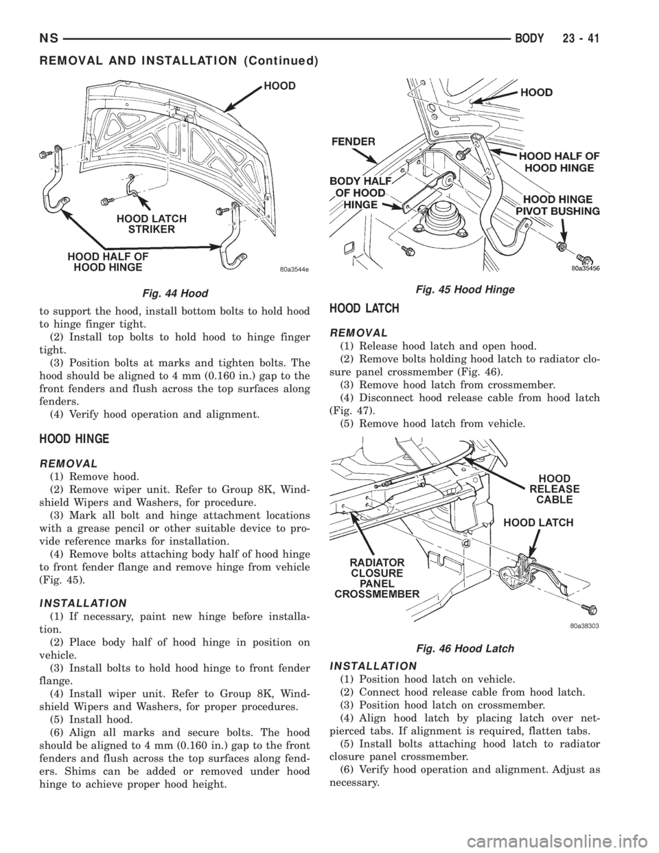
to support the hood, install bottom bolts to hold hood
to hinge finger tight.
(2) Install top bolts to hold hood to hinge finger
tight.
(3) Position bolts at marks and tighten bolts. The
hood should be aligned to 4 mm (0.160 in.) gap to the
front fenders and flush across the top surfaces along
fenders.
(4) Verify hood operation and alignment.
HOOD HINGE
REMOVAL
(1) Remove hood.
(2) Remove wiper unit. Refer to Group 8K, Wind-
shield Wipers and Washers, for procedure.
(3) Mark all bolt and hinge attachment locations
with a grease pencil or other suitable device to pro-
vide reference marks for installation.
(4) Remove bolts attaching body half of hood hinge
to front fender flange and remove hinge from vehicle
(Fig. 45).
INSTALLATION
(1) If necessary, paint new hinge before installa-
tion.
(2) Place body half of hood hinge in position on
vehicle.
(3) Install bolts to hold hood hinge to front fender
flange.
(4) Install wiper unit. Refer to Group 8K, Wind-
shield Wipers and Washers, for proper procedures.
(5) Install hood.
(6) Align all marks and secure bolts. The hood
should be aligned to 4 mm (0.160 in.) gap to the front
fenders and flush across the top surfaces along fend-
ers. Shims can be added or removed under hood
hinge to achieve proper hood height.
HOOD LATCH
REMOVAL
(1) Release hood latch and open hood.
(2) Remove bolts holding hood latch to radiator clo-
sure panel crossmember (Fig. 46).
(3) Remove hood latch from crossmember.
(4) Disconnect hood release cable from hood latch
(Fig. 47).
(5) Remove hood latch from vehicle.
INSTALLATION
(1) Position hood latch on vehicle.
(2) Connect hood release cable from hood latch.
(3) Position hood latch on crossmember.
(4) Align hood latch by placing latch over net-
pierced tabs. If alignment is required, flatten tabs.
(5) Install bolts attaching hood latch to radiator
closure panel crossmember.
(6) Verify hood operation and alignment. Adjust as
necessary.
Fig. 44 HoodFig. 45 Hood Hinge
Fig. 46 Hood Latch
NSBODY 23 - 41
REMOVAL AND INSTALLATION (Continued)
Page 1772 of 1938

(7) Tighten attaching bolts to 11 to 16 N´m (100 to
140 in. lbs.) torque.
HOOD LATCH STRIKER
REMOVAL
(1) Release hood latch and open hood.
(2) Remove bolts holding striker to inside of hood
(Fig. 44).
(3) Remove hood latch striker from vehicle.
INSTALLATION
(1) Position hood latch striker on vehicle.
(2) Install bolts to hold hood latch striker to hood.
(3) Align hood latch striker to engage smoothly
into hood latch.
(4) Verify hood operation and alignment. Adjust as
necessary.
(5) Tighten attaching bolts to 11 to 16 N´m (100 to
140 in. lbs.) torque.
HOOD RELEASE CABLE
REMOVAL
(1) Remove hood latch.
(2) Disengage cable end from hood latch locking
mechanism.
(3) Slide cable case end sideways in keyhole slot of
hood latch while pinching barb on cable case closed.
(4) Remove cable from latch (Fig. 47).
(5) Remove hood release handle from instrument
panel.
(6) Disengage rubber grommet cable insulator
from hole in dash panel.
(7) Attach a suitable length of mechanic's wire to
latch end of cable to assist cable installation.
(8) Route cable back from latch through engine
compartment toward dash panel near power brake
booster (Fig. 48).
(9) Remove attaching clips from cable case.
(10) From inside vehicle, pull cable through dash
panel until mechanic's wire is exposed.
(11) Disconnect cable from mechanic's wire.(12) Remove hood release cable from vehicle.
INSTALLATION
(1) Place hood release cable in position under
instrument panel.
(2) Attach latch end of hood release cable to
mechanic's wire protruding through dash panel.
(3) Route cable forward through engine compart-
ment toward latch by pulling on mechanic's wire
(Fig. 48).
(4) Disconnect mechanic's wire from cable.
(5) Engage rubber grommet cable insulator into
hole in dash panel.
(6) Install hood release handle into instrument
panel.
(7) Place cable in position on latch.
(8) Slide cable case end sideways into keyhole slot
of hood latch.
(9) Engage cable end into hood latch locking mech-
anism.
(10) Install hood latch.
(11) Install attaching clips to cable case and install
clips into original holes in strut tower, fender, head-
lamp area, and radiator closure panel crossmember.
HOOD RELEASE HANDLE
REMOVAL
(1) Remove lower steering column cover and knee
blocker reinforcement. Refer to Group 8E, Instru-
ment Panel and Systems for proper procedures.
(2) Remove hood latch cable.
(3) Remove screws holding hood latch release han-
dle to instrument panel brace (Fig. 49).
(4) Remove hood latch release handle from vehicle.
INSTALLATION
(1) Position hood latch release handle on vehicle.
(2) Install screws to hold hood latch release handle
to instrument panel brace.
Fig. 47 Hood Release Cable End Attachment
Fig. 48 Hood Release Cable Routing
23 - 42 BODYNS
REMOVAL AND INSTALLATION (Continued)
Page 1783 of 1938
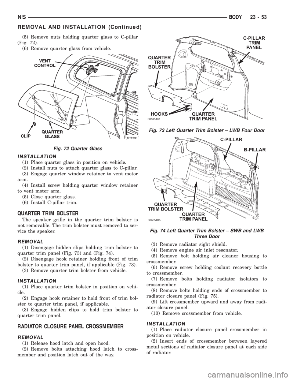
(5) Remove nuts holding quarter glass to C-pillar
(Fig. 72).
(6) Remove quarter glass from vehicle.
INSTALLATION
(1) Place quarter glass in position on vehicle.
(2) Install nuts to attach quarter glass to C-pillar.
(3) Engage quarter window retainer to vent motor
arm.
(4) Install screw holding quarter window retainer
to vent motor arm.
(5) Close quarter glass.
(6) Install C-pillar trim.
QUARTER TRIM BOLSTER
The speaker grille in the quarter trim bolster is
not removable. The trim bolster must removed to ser-
vice the speaker.
REMOVAL
(1) Disengage hidden clips holding trim bolster to
quarter trim panel (Fig. 73) and (Fig. 74).
(2) Disengage hook retainer holding front of trim
bolster to quarter trim panel, if applicable (Fig. 73).
(3) Remove quarter trim bolster from vehicle.
INSTALLATION
(1) Place quarter trim bolster in position on vehi-
cle.
(2) Engage hook retainer to hold front of trim bol-
ster to quarter trim panel, if applicable.
(3) Engage hidden clips to hold trim bolster to
quarter trim panel.
RADIATOR CLOSURE PANEL CROSSMEMBER
REMOVAL
(1) Release hood latch and open hood.
(2) Remove bolts attaching hood latch to cross-
member and position latch out of the way.(3) Remove radiator sight shield.
(4) Remove engine air inlet resonator.
(5) Remove bolt holding air cleaner housing to
crossmember.
(6) Remove screw holding coolant recovery bottle
to crossmember.
(7) Remove bolts holding radiator isolators to
crossmember.
(8) Remove bolts holding ends of crossmember to
radiator closure panel (Fig. 75).
(9) Lift crossmember upward and away from radi-
ator closure panel.
(10) Remove crossmember from vehicle.
INSTALLATION
(1) Place radiator closure panel crossmember in
position on vehicle.
(2) Insert ends of crossmember between layered
metal sections of radiator closure panel at each side
of radiator.
Fig. 72 Quarter Glass
Fig. 73 Left Quarter Trim Bolster ± LWB Four Door
Fig. 74 Left Quarter Trim Bolster ± SWB and LWB
Three Door
NSBODY 23 - 53
REMOVAL AND INSTALLATION (Continued)
Page 1784 of 1938
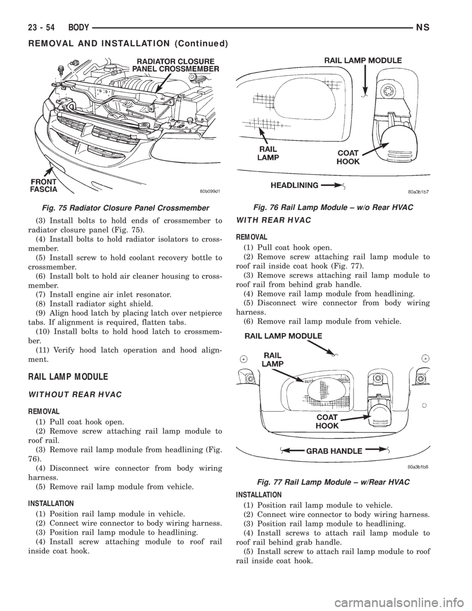
(3) Install bolts to hold ends of crossmember to
radiator closure panel (Fig. 75).
(4) Install bolts to hold radiator isolators to cross-
member.
(5) Install screw to hold coolant recovery bottle to
crossmember.
(6) Install bolt to hold air cleaner housing to cross-
member.
(7) Install engine air inlet resonator.
(8) Install radiator sight shield.
(9) Align hood latch by placing latch over netpierce
tabs. If alignment is required, flatten tabs.
(10) Install bolts to hold hood latch to crossmem-
ber.
(11) Verify hood latch operation and hood align-
ment.
RAIL LAMP MODULE
WITHOUT REAR HVAC
REMOVAL
(1) Pull coat hook open.
(2) Remove screw attaching rail lamp module to
roof rail.
(3) Remove rail lamp module from headlining (Fig.
76).
(4) Disconnect wire connector from body wiring
harness.
(5) Remove rail lamp module from vehicle.
INSTALLATION
(1) Position rail lamp module in vehicle.
(2) Connect wire connector to body wiring harness.
(3) Position rail lamp module to headlining.
(4) Install screw attaching module to roof rail
inside coat hook.
WITH REAR HVAC
REMOVAL
(1) Pull coat hook open.
(2) Remove screw attaching rail lamp module to
roof rail inside coat hook (Fig. 77).
(3) Remove screws attaching rail lamp module to
roof rail from behind grab handle.
(4) Remove rail lamp module from headlining.
(5) Disconnect wire connector from body wiring
harness.
(6) Remove rail lamp module from vehicle.
INSTALLATION
(1) Position rail lamp module to vehicle.
(2) Connect wire connector to body wiring harness.
(3) Position rail lamp module to headlining.
(4) Install screws to attach rail lamp module to
roof rail behind grab handle.
(5) Install screw to attach rail lamp module to roof
rail inside coat hook.
Fig. 75 Radiator Closure Panel CrossmemberFig. 76 Rail Lamp Module ± w/o Rear HVAC
Fig. 77 Rail Lamp Module ± w/Rear HVAC
23 - 54 BODYNS
REMOVAL AND INSTALLATION (Continued)
Page 1831 of 1938
be 21ÉC to 27ÉC (70ÉF to 85ÉF). To test the expansion
valve:
NOTE: Liquid CO2 is required to test the expansion
valve. It is available from most welding supply facil-
ities. CO2 is also available from companies which
service and sell fire extinguishers.
(1) Connect a charging station or manifold gauge
set to the refrigerant system service ports. Verify the
refrigerant charge level.
(2) Close all doors, windows and vents to the pas-
senger compartment.
(3) Set heater A/C control to A/C, full heat,
FLOOR, and high blower.
(4) Start the engine and allow to idle (1000 rpm).
After the engine has reached running temperature,
allow the passenger compartment to heat up. This
will create the need for maximum refrigerant flow
into the evaporator.
(5) If the refrigerant charge is sufficient, discharge
(high pressure) gauge should read 965 to 1655 kPa
(140 to 240 psi). Suction (low pressure) gauge should
read 140 kPa to 207 kPa (20 psi to 30 psig). If system
cannot achieve proper pressure readings, replace the
expansion valve. If pressure is correct, proceed with
test.
WARNING: PROTECT SKIN AND EYES FROM CON-
TACTING CO2 PERSONAL INJURY CAN RESULT.
(6) If suction side low pressure is within specified
range, freeze the expansion valve control head for 30
seconds. Use a super cold substance (liquid CO2).Do
not spray R-134a or R-12 Refrigerant on the
expansion valve for this test.Suction side low
pressure should drop by 10 psi. If not, replace expan-
sion valve.
(7) Allow expansion valve to thaw. The low pres-
sure gauge reading should stabilize at 140 kPa to
240 kPa (20 psi to 30 psig). If not, replace expansion
valve.
(8) When expansion valve test is complete, test
A/C overall performance. Remove all test equipment
before returning vehicle to use.
HEATER PERFORMANCE TEST
PRE-DIAGNOSTIC PREPARATIONS
Review Safety Precautions and Warnings in this
group before performing the following procedures.
Check the coolant level, drive belt tension, vacuum
line connections, radiator air flow and fan operation.
Start engine and allow to warm up to normal tem-
perature.WARNING: DO NOT REMOVE RADIATOR CAP
WHEN ENGINE IS HOT, PERSONAL INJURY CAN
RESULT.
If vehicle has been run recently, wait 15 minutes
before removing cap. Place a rag over the cap and
turn it to the first safety stop. Allow pressure to
escape through the overflow tube. When the system
stabilizes, remove the cap completely.
MAXIMUM HEATER OUTPUT: TEST AND
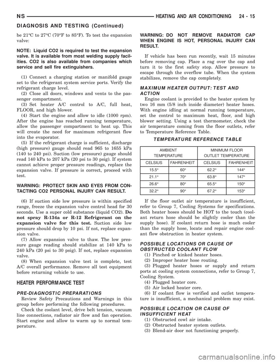
ACTION
Engine coolant is provided to the heater system by
two 16 mm (5/8 inch inside diameter) heater hoses.
With engine idling at normal running temperature,
set the control to maximum heat, floor, and high
blower setting. Using a test thermometer, check the
air temperature coming from the floor outlets, refer
to Temperature Reference Table.
If the floor outlet air temperature is insufficient,
refer to Group 7, Cooling Systems for specifications.
Both heater hoses should be HOT to the touch (cool-
ant return hose should be slightly cooler than the
supply hose). If coolant return hose is much cooler
than the supply hose, locate and repair engine cool-
ant flow obstruction in heater system.
POSSIBLE LOCATIONS OR CAUSE OF
OBSTRUCTED COOLANT FLOW
(1) Pinched or kinked heater hoses.
(2) Improper heater hose routing.
(3) Plugged heater hoses or supply and return
ports at cooling system connections, refer to Group 7,
Cooling System.
(4) Plugged heater core.
(5) Air locked heater core.
(6) If coolant flow is verified and outlet tempera-
ture is insufficient, a mechanical problem may exist.
POSSIBLE LOCATION OR CAUSE OF
INSUFFICIENT HEAT
(1) Obstructed cowl air intake.
(2) Obstructed heater system outlets.
(3) Blend-air door not functioning properly.
TEMPERATURE REFERENCE TABLE
AMBIENT
TEMPERATUREMINIMUM FLOOR
OUTLET TEMPERATURE
CELSIUS FAHRENHEIT CELSIUS FAHRENHEIT
15.5É 60É 62.2É 144É
21.1É 70É 63.8É 147É
26.6É 80É 65.5É 150É
32.2É 90É 67.2É 153É
NSHEATING AND AIR CONDITIONING 24 - 15
DIAGNOSIS AND TESTING (Continued)
Page 1832 of 1938
TEMPERATURE CONTROL
If temperature cannot be adjusted with the TEMP
lever on the control panel, the following could require
service:
(1) Blend-air door binding.
(2) Faulty blend-air door motor.
(3) Improper engine coolant temperature.
(4) Faulty Instrument Panel Control.
SYSTEM CHARGE LEVEL TEST
The procedure below should be used to check
and/or fill the refrigerant charge in the air condition-
ing system.
NOTE: The amount of R134a refrigerant that the air
conditioning system holds is:
²Without rear A/C± .96 kg (34 oz. or 2.13 lbs.)
²With Rear A/C± 1.36 kg (48 oz. or 3.00 lbs.)
NOTE: Low Charge, condition may be described
as:
²Loss of A/C performance
²Fog from A/C outlets
²evaporator may have a HISS sound
There are two different ways the system can be
tested:
²With a scan tool (DRB), thermocouple and the
Charge Determination Graph. Use the scan tool
(DRB) diagnostic topic: Engine±System Monitors, A/C
Pressure.
²Using a manifold gauge set, a thermocouple and
the Charge Determination Graph.
It is recommended to use the gauges or reclaim/re-
cycle equipment.
WARNING: AVOID BREATHING A/C REFRIGERANT
AND LUBRICANT VAPOR OR MIST. EXPOSURE MAY
IRRITATE EYES, NOSE AND THROAT. USE ONLY
APPROVED SERVICE EQUIPMENT MEETING SAE
REQUIREMENTS TO DISCHARGE R-134a SYSTEM.
IF ACCIDENTAL SYSTEM DISCHARGE OCCURS,
VENTILATE WORK AREA BEFORE RESUMING SER-
VICE.
R-134a SERVICE EQUIPMENT OR VEHICLE A/C
SYSTEM SHOULD NOT BE PRESSURE TESTED OR
LEAK TESTED WITH COMPRESSED AIR. SOME
MIXTURES OF AIR/R-134a HAVE BEEN SHOWN TO
BE COMBUSTIBLE AT ELEVATED PRESSURES.
THESE MIXTURES ARE POTENTIALLY DANGER-
OUS AND MAY RESULT IN FIRE OR EXPLOSION
CAUSING INJURY OR PROPERTY DAMAGE.
(1) Establish your preferred method of measuring
liquid line pressure. Use a manifold gauge set or a
DRB scan tool.(2) Attach a clamp-on thermocouple (P.S.E. 66-324-
0014 or 80PK-1A) or equivalent to the liquid line. It
must be placed as close to the A/C Pressure Trans-
ducer as possible to observe liquid line temperature.
Refer to ªThermocouple Probeº in this section for
more information on probe.
(3) The vehicle must be in the following modes:
²Transaxle in Park
²Engine Idling at 700 rpm
²A/C Controls Set to Outside Air
²Panel Mode
²Full Cool
²High Blower motor, (vehicle equipped with rear
A/C turn rear blower motor ON HIGH)
²A/C Button in the ON position
²Vehicle Windows Open.
²Recirc. button turned OFF
(4) Operate system for a couple of minutes to allow
the system to stabilize.
(5) Set system pressure to about 1793 kPa (260
psi) by placing a piece of cardboard over part of the
front side of the condenser. To place cardboard prop-
erly, remove the upper radiator-condenser cover.
Insert cardboard between condenser and radiator
front. This will maintain a constant pressure.
(6) Observe Liquid Line pressure and Liquid line
temperature. Using theCharge Determination
Chartdetermine where the system is currently oper-
ating. If the system is in the undercharged region,
ADD 0.057 Kg. (2 oz.) to the system and recheck
readings. If the system is in the overcharged region,
RECLAIM 0.057 Kg. (2 oz.) from the system and
recheck readings. Continue this process until the sys-
tem readings are in the proper charge area on the
Charge Determination Chart.
(7) The same procedure can be performed using
the scan tool (DRB). To determine liquid line pres-
sure, attach the scan tool, go to System Moni-
tors±A/C Pressure. Observe liquid line pressure from
A/C Pressure Transducer on digital display and digi-
tal thermometer. Refer toCharge Determination
Chartand determine where the system is operating.
SERVICE PROCEDURES
R-134a REFRIGERANT
This vehicle uses a new type of refrigerant called
R-134a. It is a non-toxic, non-flammable, clear color-
less liquefied gas.
R-134a refrigerant is not compatible with R-12
refrigerant in an air conditioning system. Even a
small amount of R-12 in a R-134a system could cause
compressor failure, refrigerant oil to sludge and/or
poor performance.Never add any other type of
refrigerant to a system designed to use R-134a
refrigerant. System failure will occur.
24 - 16 HEATING AND AIR CONDITIONINGNS
DIAGNOSIS AND TESTING (Continued)