torque CHRYSLER VOYAGER 1996 Service Manual
[x] Cancel search | Manufacturer: CHRYSLER, Model Year: 1996, Model line: VOYAGER, Model: CHRYSLER VOYAGER 1996Pages: 1938, PDF Size: 55.84 MB
Page 1051 of 1938

ENGINE
CONTENTS
page page
2.4L ENGINE............................ 14
3.0L ENGINE............................ 61
3.3/3.8L ENGINE........................ 93ENGINE DIAGNOSIS....................... 7
STANDARD SERVICE PROCEDURES.......... 1
STANDARD SERVICE PROCEDURES
INDEX
page page
GENERAL INFORMATION
CRANKSHAFT SPROCKET BOLT ACCESS
PLUG................................ 2
ENGINE CORE PLUGS.................... 2
ENGINE OIL SERVICE..................... 5
ENGINE OIL............................. 5
ENGINE PERFORMANCE.................. 2FORM-IN-PLACE GASKETS................. 1
HONING CYLINDER BORES................ 3
HYDROSTATIC LOCKED ENGINE............ 5
MEASURING MAIN BEARING AND
CONNECTING ROD BEARING
CLEARANCES......................... 3
REPAIR OF DAMAGED OR WORN THREADS . . . 4
GENERAL INFORMATION
FORM-IN-PLACE GASKETS
There are numerous places where form-in-place
gaskets are used on the engine. Care must be taken
when applying form-in-place gaskets.Do not use
form-in-place gasket material unless specified.
Bead size, continuity, and location are of great impor-
tance. Too thin a bead can result in leakage while too
much can result in spill-over, a continuous bead of
the proper width is essential to obtain a leak-free
joint.
Two types of form-in-place gasket materials are
used in the engine.MopartSilicone Rubber Adhe-
sive Sealant andMopartGasket Maker, (anaerobic)
each have different properties and cannot be used
interchangeably.
CAUTION: Silicone sealer and anaerobic sealers
each will inhibit the cure of the other and care
should be taken to keep usages separated as much
as possible.
MOPARTSILICONE RUBBER ADHESIVE
SEALANT
MopartSilicone Rubber Adhesive Sealant or
equivalent, normally black in color, is available in
three ounce tubes. Moisture in the air causes the
MopartSilicone Rubber Adhesive Sealant material
to cure. This material is normally used on flexible
metal flanges. It has a shelf life of one year and will
not properly cure if over age. Always inspect the
package for the expiration date before use.
MOPARTGASKET MAKER
MopartGasket Maker is an anaerobic type gasket
material normally red in color. The material cures in
the absence of air when squeezed between two metal-
lic surfaces. It will not cure if left in the uncovered
tube. It is normally red in color. The anaerobic mate-
rial is for use between two machined surfaces. Do not
use on flexible metal flanges.
MOPARTTORQUE CURE GASKET MAKER
MopartTorque Cure Gasket Maker is a unique
anaerobic type gasket material to be usedONLY
between the bedplate and engine block. The material
cures in the absence of air when torqued between
two metallic surfaces. It will not cure if left in the
uncovered tube. This anaerobic material is specially
NSENGINE 9 - 1
Page 1052 of 1938
made to seal the area between the bedplate and cyl-
inder block without disturbing the bearing clearance
or alignment of these components.
GASKET DISASSEMBLY
Parts assembled with form-in-place gaskets may be
disassembled without unusual effort. In some
instances, it may be necessary to lightly tap the part
with a mallet or other suitable tool to break the seal
between the mating surfaces. A flat gasket scraper
may also be lightly tapped into the joint but care
must be taken not to damage the mating surfaces.
SURFACE PREPARATION
Scrape clean or wire brush all gasket surfaces to
remove all loose material. Inspect stamped parts to
ensure gasket rails are flat. Gasket surfaces must be
free of oil and dirt. Make sure old gasket material is
removed from blind attaching holes.
FORM-IN-PLACE GASKET APPLICATION
Assembling parts using a form-in-place gasket
requires care but it's easier then using precut gas-
kets.
MopartGasket Maker material should be applied
sparingly 1 mm (0.040 in.) diameter or less of sealant
to one gasket surface. Be certain the material sur-
rounds each mounting hole. Excess material can eas-
ily be wiped off. Components should be torqued in
place within 15 minutes. The use of a locating dowel
is recommended during assembly to prevent smear-
ing the material off location.
TheMopartSilicone Rubber Adhesive Sealant
gasket material or equivalent should be applied in a
continuous bead approximately 3 mm (0.120 in.) in
diameter. All mounting holes must be circled. For
corner sealing, a 3.17 or 6.35 mm (1/8 or 1/4 in.) drop
is placed in the center of the gasket contact area.
Uncured sealant may be removed with a shop towels.
Components should be torqued in place while the
sealant is still wet to the touch (within 10 minutes).
The usage of a locating dowel is recommended during
assembly to prevent smearing of material off loca-
tion.
CRANKSHAFT SPROCKET BOLT ACCESS PLUG
An Access plug is located in the right inner fender
shield. Remove the plug and insert the proper size
socket, extension and ratchet, when crankshaft rota-
tion is necessary.
ENGINE CORE PLUGS
REMOVAL
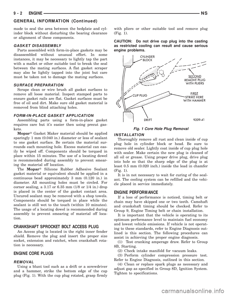
Using a blunt tool such as a drift or a screwdriver
and a hammer, strike the bottom edge of the cup
plug (Fig. 1). With the cup plug rotated, grasp firmlywith pliers or other suitable tool and remove plug
(Fig. 1).
CAUTION: Do not drive cup plug into the casting
as restricted cooling can result and cause serious
engine problems.
INSTALLATION
Thoroughly remove all rust and clean inside of cup
plug hole in cylinder block or head. Be sure to
remove old sealer. Lightly coat inside of cup plug hole
with sealer. Make certain the new plug is cleaned of
all oil or grease. Using proper drive plug, drive plug
into hole so that the sharp edge of the plug is at
least 0.5 mm (0.020 inch.) inside the lead in chamfer
(Fig. 1).
It is in not necessary to wait for curing of the seal-
ant. The cooling system can be refilled and the vehi-
cle placed in service immediately.
ENGINE PERFORMANCE
If a loss of performance is noticed, timing belt or
chain may have skipped one or two teeth. Camshaft
and crankshaft timing should be checked. Refer to
Group 9, Engine Timing belt or chain installation.
It is important that the vehicle is operating to its
optimum performance level to maintain fuel economy
and lowest vehicle emissions. If vehicle is not operat-
ing to these standards, refer to Engine Diagnosis out-
lined is this section. The following procedures can
assist in achieving the proper engine diagnosis.
(1) Test cranking amperage draw. Refer to Group
8B, Starting.
(2) Check intake manifold for vacuum leaks.
(3) Perform cylinder compression pressure test.
Refer to Engine Diagnosis, outlined in this section.
(4) Clean or replace spark plugs as necessary and
adjust gap as specified in Group 8D, Ignition System.
Tighten to specifications.
Fig. 1 Core Hole Plug Removal
9 - 2 ENGINENS
GENERAL INFORMATION (Continued)
Page 1054 of 1938

ENGINE WITH 5 MAIN BEARINGS
²When checking #1 main bearing shim #2 main
bearing.
²When checking #2 main bearing shim #1 & 3
main bearing.
²When checking #3 main bearing shim #2 & 4
main bearing.
²When checking #4 main bearing shim #3 & 5
main bearing.
²When checking #5 main bearing shim #4 main
bearing.
ENGINE WITH 4 MAIN BEARING
²When checking #1 main bearing shim # 2 main
bearing.
²When checking #2 main bearing shim #1 & #3
main bearing.
²When checking #3 main bearing shim #2 & #4
main bearing.
²When checking #4 main bearing shim #3 main
bearing.
NOTE: REMOVE ALL SHIMS BEFORE REASSEM-
BLING ENGINE
ALTERNATIVE METHOD
The weight of the crankshaft can be supported by a
jack under the counterweight adjacent to the bearing
being checked.
PLASTIGAGE PROCEDURE
(1) Remove oil film from surface to be checked.
Plastigage is soluble in oil.
(2) Place a piece of Plastigage across the entire
width of the bearing shell in the cap approximately
6.35 mm (1/4 in.) off center and away from the oil
holes (Fig. 3). (In addition, suspected areas can be
checked by placing the Plastigage in the suspected
area). Torque the bearing cap bolts of the bearing
being checked to the proper specifications.
(3) Remove the bearing cap and compare the
width of the flattened Plastigage (Fig. 4) with the
metric scale provided on the package. Locate the
band closest to the same width. This band shows theamount of clearance in thousandths of a millimeter.
Differences in readings between the ends indicate the
amount of taper present. Record all readings taken.
Refer to Engine Specifications.Plastigage gener-
ally is accompanied by two scales. One scale is
in inches, the other is a metric scale.
NOTE: Plastigage is available in a variety of clear-
ance ranges. Use the most appropriate range for
the specifications you are checking.
CONNECTING ROD BEARING CLEARANCE
Engine connecting rod bearing clearances can be
determined by use of Plastigage or equivalent. The
following is the recommended procedure for the use
of Plastigage:
(1) Rotate the crankshaft until the connecting rod
to be checked is at the bottom of its stroke.
(2) Remove oil film from surface to be checked.
Plastigage is soluble in oil.
(3) Place a piece of Plastigage across the entire
width of the bearing shell in the bearing cap approx-
imately 6.35 mm (1/4 in.) off center and away from
the oil hole (Fig. 3). In addition, suspect areas can be
checked by placing plastigage in the suspect area.
(4) Assemble the rod cap with Plastigage in place.
Tighten the rod cap to the specified torque.Do not
rotate the crankshaft while assembling the cap
or the Plastigage may be smeared, giving inac-
curate results.
(5) Remove the bearing cap and compare the
width of the flattened Plastigage (Fig. 4) with the
scale provided on the package. Locate the band clos-
est to the same width. This band indicates the
amount of oil clearance. Differences in readings
between the ends indicate the amount of taper
present. Record all readings taken. Refer to Engine
Specifications.Plastigage generally is accompa-
nied by two scales. One scale is in inches, the
other is a metric scale. If the bearing clearance
exceeds 0.076 mm (0.003 in.) replace bearing.
NOTE: Plastigage is available in a variety of clear-
ance ranges. Use the most appropriate range for
the specifications you are checking.
REPAIR OF DAMAGED OR WORN THREADS
Damaged or worn threads (including aluminum
head spark plug threads) can be repaired. Essen-
tially, this repair consists of drilling out worn or
damaged threads, tapping the hole with a special
Heli-Coil Tap, (or equivalent) and installing an insert
into the tapped hole. This brings the hole back to its
original thread size.
Fig. 4 Clearance Measurement
9 - 4 ENGINENS
GENERAL INFORMATION (Continued)
Page 1059 of 1938
(2) Add an oil soluble dye (use as recommended by
manufacturer). Start the engine and let idle for
approximately 15 minutes. Check the oil dipstick to
make sure the dye is thoroughly mixed as indicated
with a bright yellow color under a black light.
(3) Using a black light, inspect the entire engine
for fluorescent dye, particularly at the suspected area
of oil leak. If the oil leak is found and identified,
repair per service manual instructions.
(4) If dye is not observed, drive the vehicle at var-
ious speeds for approximately 24km (15 miles), and
repeat inspection.
(5)If the oil leak source is not positively
identified at this time, proceed with the air leak
detection test method as follows:
(6) Disconnect the fresh air hose (makeup air) at
the cylinder head cover and plug or cap the nipple on
the cover.
(7) Remove the PCV valve hose from the cylinder
head cover. Cap or plug the PCV valve nipple on the
cover.
(8) Attach an air hose with pressure gauge and
regulator to the dipstick tube.
CAUTION: Do not subject the engine assembly to
more than 20.6 kpa (3 PSI) of test pressure.
(9) Gradually apply air pressure from 1 psi to 2.5
psi maximum while applying soapy water at the sus-
pected source. Adjust the regulator to the suitable
test pressure that provide the best bubbles which
will pinpoint the leak source. If the oil leak is
detected and identified, repair per service manual
procedures.
(10) If the leakage occurs at the rear oil seal area,
refer to the section, Inspection for Rear Seal Area
Leak.
(11) If no leaks are detected, turn off the air sup-
ply and remove the air hose and all plugs and caps.
Install the PCV valve and breather cap hose. Proceed
to next step.
(12) Clean the oil off the suspect oil leak area
using a suitable solvent. Drive the vehicle at various
speeds approximately 24 km (15 miles). Inspect the
engine for signs of an oil leak by using a black light.INSPECTION FOR REAR SEAL AREA LEAKS
Since it is sometimes difficult to determine the
source of an oil leak in the rear seal area of the
engine, a more involved inspection is necessary. The
following steps should be followed to help pinpoint
the source of the leak.
If the leakage occurs at the crankshaft rear oil seal
area:
(1) Disconnect the battery.
(2) Raise the vehicle.
(3) Remove torque converter or clutch housing
cover and inspect rear of block for evidence of oil.
Use a black light to check for the oil leak. If a leak is
present in this area remove transmission for further
inspection.
(a) Circular spray pattern generally indicates
seal leakage or crankshaft damage.
(b) Where leakage tends to run straight down,
possible causes are a porous block, oil galley cup
plug, bedplate to cylinder block mating surfaces
and seal bore. See proper repair procedures for
these items.
(4) If no leaks are detected, pressurized the crank-
case as outlined in the, Inspection (Engine oil Leaks
in general)
CAUTION: Do not exceed 20.6 kPa (3 psi).
(5) If the leak is not detected, very slowly turn the
crankshaft and watch for leakage. If a leak is
detected between the crankshaft and seal while
slowly turning the crankshaft, it is possible the
crankshaft seal surface is damaged. The seal area on
the crankshaft could have minor nicks or scratches
that can be polished out with emery cloth.
CAUTION: Use extreme caution when crankshaft
polishing is necessary to remove minor nicks and
scratches. The crankshaft seal flange is especially
machined to complement the function of the rear oil
seal.
(6) For bubbles that remain steady with shaft
rotation, no further inspection can be done until dis-
assembled.
(7) After the oil leak root cause and appropriate
corrective action have been identified. Refer to Rear
Crankshaft Seals, for proper replacement procedures.
NSENGINE 9 - 9
DIAGNOSIS AND TESTING (Continued)
Page 1062 of 1938
ENGINE DIAGNOSISÐMECHANICAL
CONDITION POSSIBLE CAUSES CORRECTION
NOISY VALVES 1. High or low oil level in
crankcase.1. Check for correct oil level.
2. Thin or diluted oil. 2. Change oil to correct viscosity.
3. Low oil pressure. 3. Check engine oil level.
4. Dirt in tappets/lash adjusters. 4. Replace rocker arm/hydraulic
lash adjuster assembly.
5. Worn rocker arms. 5. Inspect oil supply to rocker arms.
6. Worn tappets/lash adjusters. 6. Install new rocker arm/hydraulic
lash adjuster assembly.
7. Worn valve guides. 7. Ream and install new valves with
oversize stems.
8. Excessive runout of valve seats
on valve faces.8. Grind valve seats and valves.
9. Missing adjuster pivot. 9. Replace rocker arm/hydraulic
lash adjuster assembly.
CONNECTING ROD NOISE 1. Insuffient oil supply. 1. Check engine oil level.
2. Low oil pressure. 2. Check engine oil level. Inspect oil
pump relief valve and spring.
3. Thin or diluted oil. 3. Change oil to correct viscosity.
4. Excessive bearing clearance. 4. Measure bearings for correct
clearance. Repair as necessary.
5. Connecting rod journal
out-of-round.5. Replace crankshaft or grind
surface.
6. Misaligned connecting rods. 6. Replace bent connecting rods.
MAIN BEARING NOISE 1. Insufficient oil supply. 1. Check engine oil level.
2. Low oil pressure. 2. Check engine oil level. Inspect oil
pump relief valve and spring.
3. Thin or diluted oil. 3. Change oil to correct viscosity.
4. Excessive bearing clearance. 4. Measure bearings for correct
clearance. Repair as necessary.
5. Excessive end play. 5. Check thrust bearing for wear on
flanges.
6. Crankshaft journal out-of-round
or worn.6. Replace crankshaft or grind
journals.
7. Loose flywheel or torque
converter.7. Tighten to correct torque.
OIL PRESSURE DROP 1. Low oil level. 1. Check engine oil level.
2. Faulty oil pressure sending unit. 2. Install new sending unit.
3. Low oil pressure. 3. Check sending unit and main
bearing oil clearance.
4. Clogged oil filter. 4. Install new oil filter.
5. Worn parts in oil pump. 5. Replace worn parts or pump.
6. Thin or diluted oil. 6. Change oil to correct viscosity.
7. Excessive bearing clearance. 7. Measure bearings for correct
clearance.
8. Oil pump relief valve stuck. 8. Remove valve and inspect, clean,
or replace.
9. Oil pump suction tube loose. 9. Remove oil pan and install new
tube or clean, if necessary.
10. Oil pump cover warped or
cracked.10. Install new oil pump.
9 - 12 ENGINENS
DIAGNOSIS AND TESTING (Continued)
Page 1064 of 1938
2.4L ENGINE
INDEX
page page
DESCRIPTION AND OPERATION
ENGINE COMPONENTS.................. 15
ENGINE IDENTIFICATION................. 14
ENGINE LUBRICATION SYSTEM............ 14
DIAGNOSIS AND TESTING
CHECKING ENGINE OIL PRESSURE......... 16
SERVICE PROCEDURES
CRANKSHAFT END PLAY................. 20
FITTING CONNECTING ROD BEARINGS..... 18
FITTING MAIN BEARINGS................. 19
FITTING PISTON RINGS.................. 16
FITTING PISTONS....................... 16
VALVE SERVICE RECONDITION............ 21
REMOVAL AND INSTALLATION
BALANCE SHAFTS CARRIER ASSEMBLY..... 30
CAMSHAFT FOLLOWER.................. 30
CAMSHAFT OIL SEALÐFRONT............. 41
CAMSHAFT............................ 28
CRANKSHAFT OIL SEALÐFRONT........... 42
CRANKSHAFT OIL SEALÐREAR............ 43
CRANKSHAFT.......................... 46
CYLINDER HEAD COVER................. 28
CYLINDER HEAD........................ 34
ENGINE ASSEMBLY...................... 26
ENGINE MOUNTÐFRONT................. 23
ENGINE MOUNTÐLEFT.................. 24
ENGINE MOUNTÐREAR.................. 25
ENGINE MOUNTÐRIGHT................. 24HYDRAULIC LASH ADJUSTER.............. 33
OILFILTER ............................ 47
OILPAN ............................... 45
OIL PUMP............................. 47
PISTON AND CONNECTING ROD........... 49
STRUCTURAL COLLAR................... 25
TIMING BELT COVER.................... 37
TIMING BELT TENSIONER ASSEMBLY....... 40
TIMING BELT........................... 37
VALVE SPRINGS AND
VALVE SEALS IN VEHICLE............... 33
VALVES AND VALVE SPRINGS............. 35
VIBRATION DAMPER.................... 36
DISASSEMBLY AND ASSEMBLY
OIL PUMP............................. 50
CLEANING AND INSPECTION
OIL PUMP............................. 52
CRANKSHAFT.......................... 52
CYLINDER BLOCK....................... 54
CYLINDER HEAD........................ 51
VALVE AND VALVE SPRING................ 51
ADJUSTMENTS
ENGINE MOUNTS....................... 54
SPECIFICATIONS
2.4L ENGINE........................... 55
TORQUE CHART 2.4L.................... 57
SPECIAL TOOLS
2.4L ENGINE........................... 58
DESCRIPTION AND OPERATION
ENGINE IDENTIFICATION
The engine identification number is located on the
rear of the cylinder block (Fig. 1).
ENGINE LUBRICATION SYSTEM
OIL PAN
A structural die cast aluminum oil pan provides
lower engine protection as well as serving as the
engine oil reservoir. Oil pan is attached to block and
sealed with a gasket. The oil pickup tube has a
strainer and cover.
PRESSURE LUBRICATION
Oil drawn up through the pickup tube is pressur-
ized by the pump and routed through the full flow fil-
ter to the main oil gallery running the length of thecylinder block. Oil pickup, pump and check valve pro-
vide oil flow to the main oil gallery.
MAIN/ROD BEARINGS
A diagonal hole in each bulkhead feeds oil to each
main bearing. Drilled passages within the crankshaft
route oil from main bearing journals to connecting
rod journals.
CAMSHAFT/HYDRAULIC LASH ADJUSTERS
A vertical hole at the number five bulkhead routes
pressurized oil through a restrictor up past a cylin-
der head bolt to an oil gallery running the length of
the cylinder head. The camshaft journals are par-
tially slotted to allow a predetermined amount of
pressurized oil to pass into the bearing cap cavities
with small holes directed to spray lubricate the cam-
shaft lobes.
9 - 14 2.4L ENGINENS
Page 1066 of 1938

sealing and a chrome plated taper faced intermediate
ring for additional cylinder pressure control. There
are also standard oil control rings.
CYLINDER HEAD:Features a Dual Over Head
Camshaft (DOHC) 4 valves per cylinder cross flow
design. The valves are arranged in two inline banks,
with the ports of the bank of two intake valves per
cylinder facing toward the radiator side of engine
and ports of the bank of two exhaust valves per cyl-
inder facing toward the dash panel. Incorporates
powder metal valve guides and seats. Integral oil gal-
leys within the cylinder head supplies oil to the
hydraulic lash adjusters, camshaft and valve mecha-
nisms.
CAMSHAFTS:The nodular iron camshafts have
six bearing journals and 2 cam lobes per cylinder.
Flanges at the rear journals control camshaft end
play. Provision for cam position sensor is located on
the intake camshaft at the rear of cylinder head. A
hydrodynamic oil seal is used for oil control at the
front of the camshaft.
VALVES:4 valves per cylinder are actuated by
roller cam followers which pivot on stationary
hydraulic lash adjusters. All valves have 6 mm diam-
eter chrome plated valve stems. The valve sizes are
34.8 mm (1.370 inch.) diameter intake valves and
30.5 mm (1.20 inch.) diameter exhaust valves. Viton
rubber valve stem seals are integral with the spring
seats. Valve springs, spring retainers, and locks are
conventional.
INTAKE MANIFOLD:The intake manifold is a
two piece aluminum casting, attached to the cylinder
head with ten screws. This long branch fan design
enhances low and midspeed torque, while minimizing
undesirable inlet noise.
EXHAUST MANIFOLD:The exhaust manifold is
made of cast iron for strength and high tempera-
tures.
ENGINE LUBRICATION:Refer to Group 0
Lubrication and Maintenance for recommended oil to
be used in various engine application. System is full
flow filtration, pressure feed type. The oil pump is
mounted in the front engine cover and driven by the
crankshaft. Pressurized oil is then routed through
the main oil gallery, running the length of the cylin-
der block, supplying main and rod bearings with fur-
ther routing. Pistons are lubricated from rod bearing
throw off and lubricating slots on the connecting rod
assemblies. Camshaft and valve mechanisms are
lubricated from a full length cylinder head oil gallery
supplied from the crankcase main oil gallery.DIAGNOSIS AND TESTING
CHECKING ENGINE OIL PRESSURE
(1) Remove oil pressure sending unit and install
gauge assembly C-3292.
(2) Run engine until thermostat opens.
CAUTION: If oil pressure is 0 at idle, Do Not Run
engine at 3000 RPM
(3) Oil Pressure:Curb Idle25 kPa (4 psi) mini-
mum3000 RPM170/550 kPa (25/80 psi).
(4) If oil pressure is 0 at idle. Shut off engine,
check for pressure relief valve stuck open or a
clogged oil pickup screen.
SERVICE PROCEDURES
FITTING PISTONS
Piston and cylinder wall must be clean and dry.
Piston diameter should be measured 90 degrees to
piston pin about 14 mm (9/16 inch.) from the bottom
of the skirt as shown in (Fig. 3). Cylinder bores
should be measured halfway down the cylinder bore
and transverse to the engine crankshaft center line
shown in (Fig. 2). Refer to Cylinder Bore and Piston
Specification Chart.
Correct piston to bore clearance must be estab-
lished in order to assure quiet and economical oper-
ation.
Chrysler engines use pistons designed specifically
for each engine model. Clearance and sizing locations
vary with respect to engine model.
NOTE: Pistons and cylinder bores should be mea-
sured at normal room temperature, 70ÉF (21ÉC).
FITTING PISTON RINGS
(1) Wipe cylinder bore clean. Insert ring and push
down with piston to ensure it is square in bore. The
ring gap measurement must be made with the ring
positioning at least 12 mm (0.50 inch) from bottom of
cylinder bore. Check gap with feeler gauge (Fig. 4).
Refer to specification in Piston Ring Specification
Chart.
(2) Check piston ring to groove side clearance (Fig.
5). Refer to specification in Piston Ring Specification
Chart.
9 - 16 2.4L ENGINENS
DESCRIPTION AND OPERATION (Continued)
Page 1068 of 1938
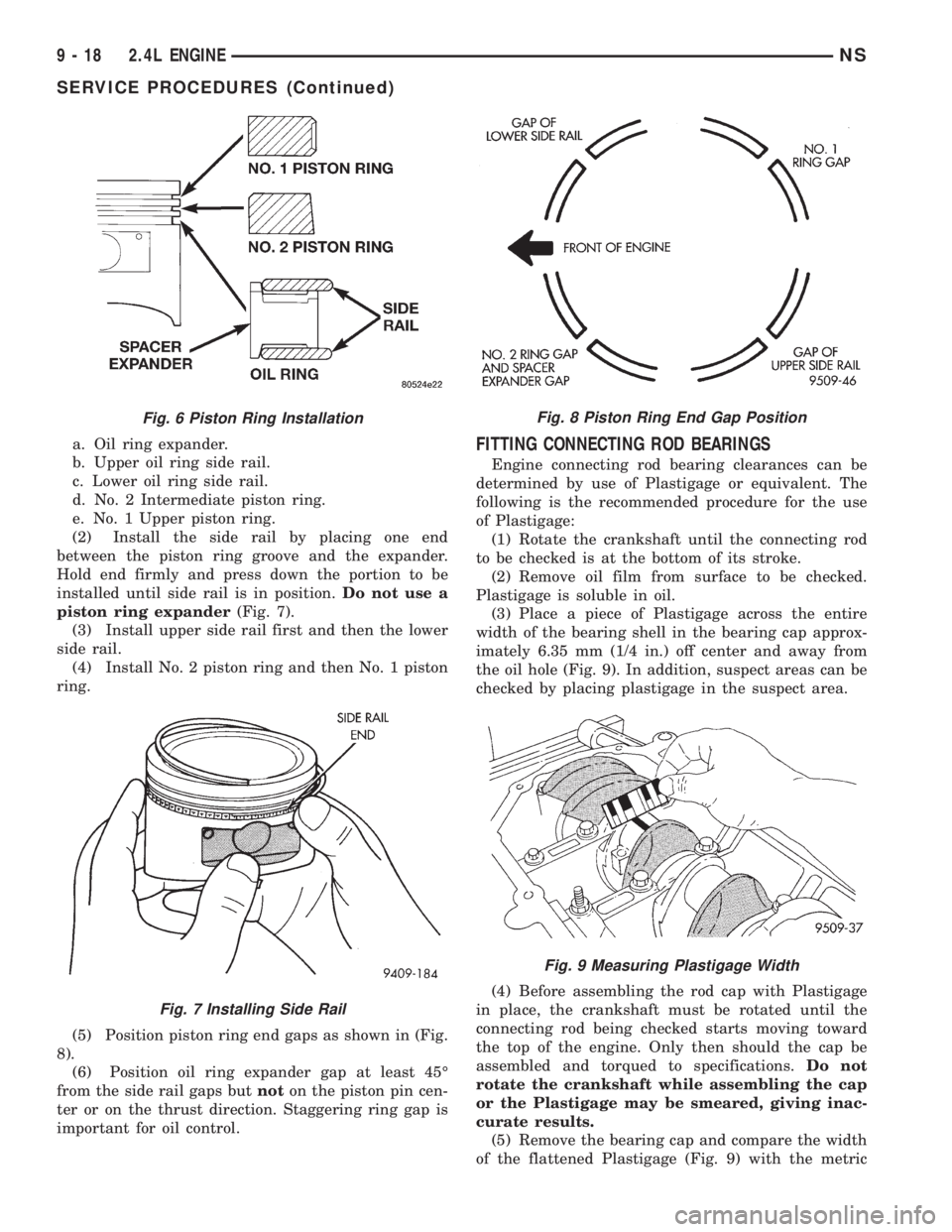
a. Oil ring expander.
b. Upper oil ring side rail.
c. Lower oil ring side rail.
d. No. 2 Intermediate piston ring.
e. No. 1 Upper piston ring.
(2) Install the side rail by placing one end
between the piston ring groove and the expander.
Hold end firmly and press down the portion to be
installed until side rail is in position.Do not use a
piston ring expander(Fig. 7).
(3) Install upper side rail first and then the lower
side rail.
(4) Install No. 2 piston ring and then No. 1 piston
ring.
(5) Position piston ring end gaps as shown in (Fig.
8).
(6) Position oil ring expander gap at least 45É
from the side rail gaps butnoton the piston pin cen-
ter or on the thrust direction. Staggering ring gap is
important for oil control.FITTING CONNECTING ROD BEARINGS
Engine connecting rod bearing clearances can be
determined by use of Plastigage or equivalent. The
following is the recommended procedure for the use
of Plastigage:
(1) Rotate the crankshaft until the connecting rod
to be checked is at the bottom of its stroke.
(2) Remove oil film from surface to be checked.
Plastigage is soluble in oil.
(3) Place a piece of Plastigage across the entire
width of the bearing shell in the bearing cap approx-
imately 6.35 mm (1/4 in.) off center and away from
the oil hole (Fig. 9). In addition, suspect areas can be
checked by placing plastigage in the suspect area.
(4) Before assembling the rod cap with Plastigage
in place, the crankshaft must be rotated until the
connecting rod being checked starts moving toward
the top of the engine. Only then should the cap be
assembled and torqued to specifications.Do not
rotate the crankshaft while assembling the cap
or the Plastigage may be smeared, giving inac-
curate results.
(5) Remove the bearing cap and compare the width
of the flattened Plastigage (Fig. 9) with the metric
Fig. 6 Piston Ring Installation
Fig. 7 Installing Side Rail
Fig. 8 Piston Ring End Gap Position
Fig. 9 Measuring Plastigage Width
9 - 18 2.4L ENGINENS
SERVICE PROCEDURES (Continued)
Page 1070 of 1938
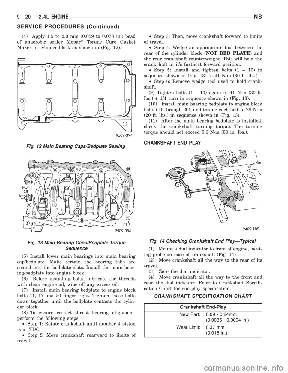
(4) Apply 1.5 to 2.0 mm (0.059 to 0.078 in.) bead
of anaerobic sealer MopartTorque Cure Gasket
Maker to cylinder block as shown in (Fig. 12).
(5) Install lower main bearings into main bearing
cap/bedplate. Make certain the bearing tabs are
seated into the bedplate slots. Install the main bear-
ing/bedplate into engine block.
(6) Before installing bolts, lubricate the threads
with clean engine oil, wipe off any excess oil.
(7) Install main bearing bedplate to engine block
bolts 11, 17 and 20 finger tight. Tighten these bolts
down together until the bedplate contacts the cylin-
der block.
(8) To ensure correct thrust bearing alignment,
perform the following steps:
²Step 1: Rotate crankshaft until number 4 piston
is at TDC.
²Step 2: Move crankshaft rearward to limits of
travel.²Step 3: Then, move crankshaft forward to limits
of travel.
²Step 4: Wedge an appropriate tool between the
rear of the cylinder block(NOT BED PLATE)and
the rear crankshaft counterweight. This will hold the
crankshaft in it's furthest forward position.
²Step 5: Install and tighten bolts (1 ± 10) in
sequence shown in (Fig. 13) to 41 N´m (30 ft. lbs.).
²Step 6: Remove wedge tool used to hold crank-
shaft.
(9) Tighten bolts (1 ± 10) again to 41 N´m (30 ft.
lbs.) + 1/4 turn in sequence shown in (Fig. 13).
(10) Install main bearing bedplate to engine block
bolts (11 through 20), and torque each bolt to 28 N´m
(20 ft. lbs.) in sequence shown in (Fig. 13).
(11) After the main bearing bedplate is installed,
check the crankshaft turning torque. The turning
torque should not exceed 5.6 N´m (50 in. lbs.).
CRANKSHAFT END PLAY
(1) Mount a dial indicator to front of engine, locat-
ing probe on nose of crankshaft (Fig. 14).
(2) Move crankshaft all the way to the rear of its
travel.
(3) Zero the dial indicator.
(4) Move crankshaft all the way to the front and
read the dial indicator. Refer to Crankshaft Specifi-
cation Chart for end-play specification.
Fig. 12 Main Bearing Caps/Bedplate Sealing
Fig. 13 Main Bearing Caps/Bedplate Torque
SequenceFig. 14 Checking Crankshaft End PlayÐTypical
CRANKSHAFT SPECIFICATION CHART
Crankshaft End-Play
New Part: 0.09 - 0.24mm
(0.0035 - 0.0094 in.)
Wear Limit: 0.37 mm
(0.015 in.)
9 - 20 2.4L ENGINENS
SERVICE PROCEDURES (Continued)
Page 1071 of 1938
OPTIONAL CRANKSHAFT END PLAY CHECK
(1) Move crankshaft all the way to the rear of its
travel using a lever inserted between a main bearing
cap and a crankshaft cheek, using care not to dam-
age any bearing surface.DO NOTloosen main bear-
ing cap.
(2) Use a feeler gauge between number three
thrust bearing and machined crankshaft surface to
determine end play.
VALVE SERVICE RECONDITION
VALVE REMOVAL
(1) With cylinder head removed, compress valve
springs using Special Tool C-3422-B or equivalent.
(2) Remove valve retaining locks, valve spring
retainers, valve stem seals and valve springs.
(3) Before removing valves,remove any burrs
from valve stem lock grooves to prevent dam-
age to the valve guides.Identify valves to insure
installation in original location.
VALVE INSPECTION
(1) Clean valves thoroughly and discard burned,
warped and cracked valves.
(2) Measure valve stems for wear. Measure stem
about 60 mm beneath the valve lock grooves.
(3) If valve stems are worn more than 0.05 mm
(0.002 in.), replace valve.
VALVE GUIDES
(1) Remove carbon and varnish deposits from
inside of valve guides with a reliable guide cleaner.
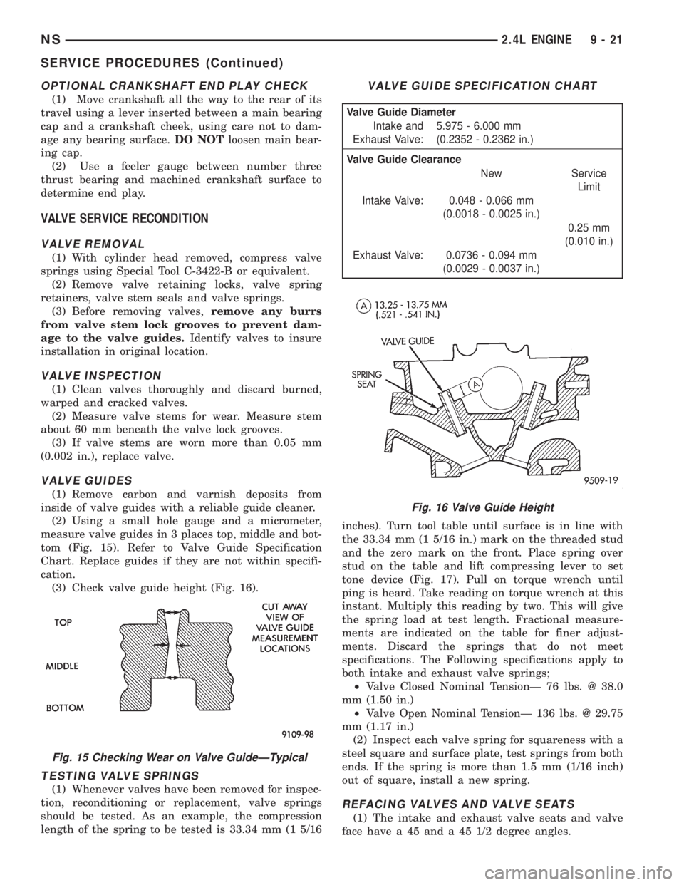
(2) Using a small hole gauge and a micrometer,
measure valve guides in 3 places top, middle and bot-
tom (Fig. 15). Refer to Valve Guide Specification
Chart. Replace guides if they are not within specifi-
cation.
(3) Check valve guide height (Fig. 16).
TESTING VALVE SPRINGS
(1) Whenever valves have been removed for inspec-
tion, reconditioning or replacement, valve springs
should be tested. As an example, the compression
length of the spring to be tested is 33.34 mm (1 5/16inches). Turn tool table until surface is in line with
the 33.34 mm (1 5/16 in.) mark on the threaded stud
and the zero mark on the front. Place spring over
stud on the table and lift compressing lever to set
tone device (Fig. 17). Pull on torque wrench until
ping is heard. Take reading on torque wrench at this
instant. Multiply this reading by two. This will give
the spring load at test length. Fractional measure-
ments are indicated on the table for finer adjust-
ments. Discard the springs that do not meet
specifications. The Following specifications apply to
both intake and exhaust valve springs;
²Valve Closed Nominal TensionÐ 76 lbs. @ 38.0
mm (1.50 in.)
²Valve Open Nominal TensionÐ 136 lbs. @ 29.75
mm (1.17 in.)
(2) Inspect each valve spring for squareness with a
steel square and surface plate, test springs from both
ends. If the spring is more than 1.5 mm (1/16 inch)
out of square, install a new spring.
REFACING VALVES AND VALVE SEATS
(1) The intake and exhaust valve seats and valve
face have a 45 and a 45 1/2 degree angles.
Fig. 15 Checking Wear on Valve GuideÐTypical
VALVE GUIDE SPECIFICATION CHART
Valve Guide Diameter
Intake and
Exhaust Valve:5.975 - 6.000 mm
(0.2352 - 0.2362 in.)
Valve Guide Clearance
New Service
Limit
Intake Valve: 0.048 - 0.066 mm
(0.0018 - 0.0025 in.)
0.25 mm
(0.010 in.)
Exhaust Valve: 0.0736 - 0.094 mm
(0.0029 - 0.0037 in.)
Fig. 16 Valve Guide Height
NS2.4L ENGINE 9 - 21
SERVICE PROCEDURES (Continued)