torque CHRYSLER VOYAGER 1996 Manual Online
[x] Cancel search | Manufacturer: CHRYSLER, Model Year: 1996, Model line: VOYAGER, Model: CHRYSLER VOYAGER 1996Pages: 1938, PDF Size: 55.84 MB
Page 252 of 1938
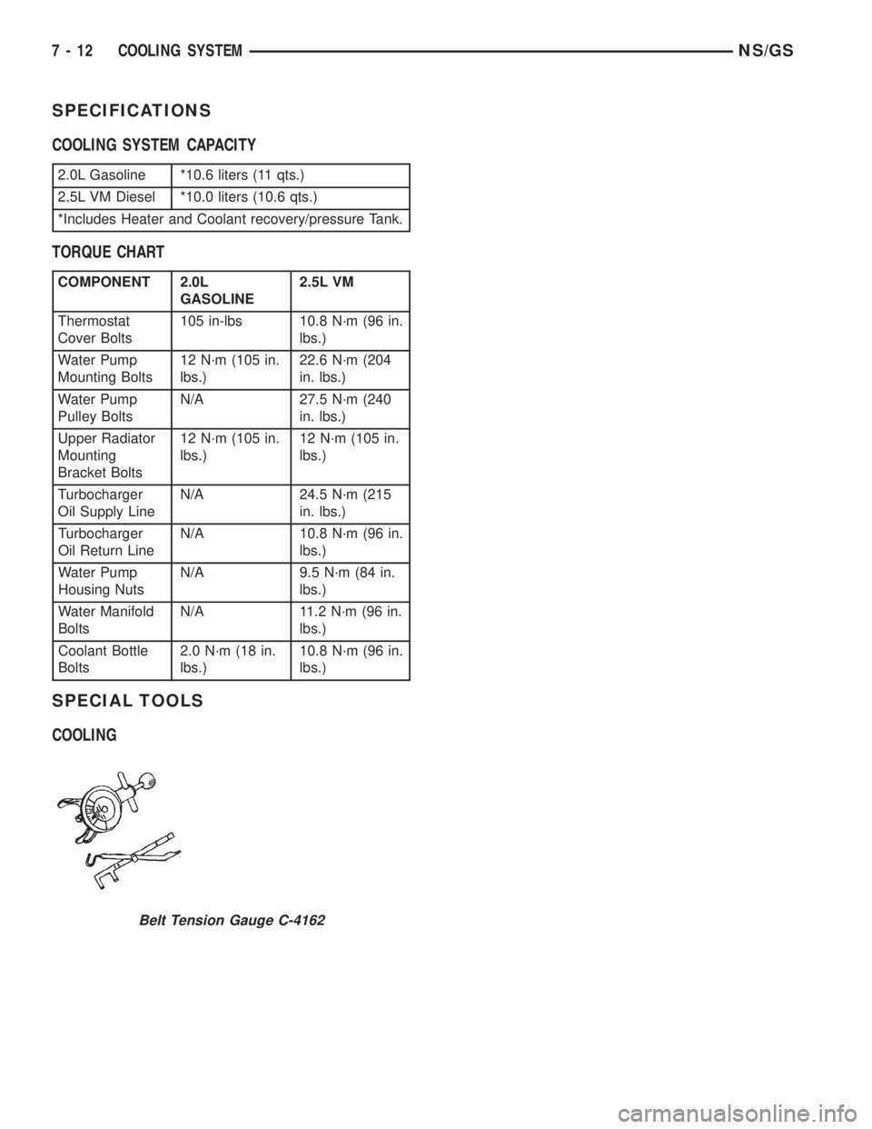
SPECIFICATIONS
COOLING SYSTEM CAPACITY
TORQUE CHART
SPECIAL TOOLS
COOLING
2.0L Gasoline *10.6 liters (11 qts.)
2.5L VM Diesel *10.0 liters (10.6 qts.)
*Includes Heater and Coolant recovery/pressure Tank.
COMPONENT 2.0L
GASOLINE2.5L VM
Thermostat
Cover Bolts105 in-lbs 10.8 N´m (96 in.
lbs.)
Water Pump
Mounting Bolts12 N´m (105 in.
lbs.)22.6 N´m (204
in. lbs.)
Water Pump
Pulley BoltsN/A 27.5 N´m (240
in. lbs.)
Upper Radiator
Mounting
Bracket Bolts12 N´m (105 in.
lbs.)12 N´m (105 in.
lbs.)
Turbocharger
Oil Supply LineN/A 24.5 N´m (215
in. lbs.)
Turbocharger
Oil Return LineN/A 10.8 N´m (96 in.
lbs.)
Water Pump
Housing NutsN/A 9.5 N´m (84 in.
lbs.)
Water Manifold
BoltsN/A 11.2 N´m (96 in.
lbs.)
Coolant Bottle
Bolts2.0 N´m (18 in.
lbs.)10.8 N´m (96 in.
lbs.)
Belt Tension Gauge C-4162
7 - 12 COOLING SYSTEMNS/GS
Page 253 of 1938

BATTERY
CONTENTS
page page
GENERAL INFORMATION
INTRODUCTION......................... 1
SAFETY PRECAUTIONS AND WARNINGS..... 1
DESCRIPTION AND OPERATION
BATTERY IGNITION OFF DRAW (IOD)........ 1
CHARGING TIME REQUIRED............... 2
DIAGNOSIS AND TESTING
BATTERY BUILT-IN TEST INDICATOR........ 2
BATTERY IGNITION OFF DRAW (IOD)........ 3
BATTERY LOAD TEST..................... 4
BATTERY OPEN CIRCUIT VOLTAGE TEST..... 6SERVICE PROCEDURES
BATTERY CHARGING..................... 6
CHARGING COMPLETELY DISCHARGED
BATTERY............................. 7
VISUAL INSPECTION..................... 7
REMOVAL AND INSTALLATION
BATTERY TRAY.......................... 9
BATTERY............................... 8
SPECIFICATIONS
BATTERY SPECIFICATIONS............... 10
TORQUE.............................. 10
GENERAL INFORMATION
INTRODUCTION
The battery stores, stabilizes, and delivers electri-
cal current to operate various electrical systems in
the vehicle. The determination of whether a battery
is good or bad is made by its ability to accept a
charge. It also must supply high-amperage current
for a long enough period to be able to start the vehi-
cle. The capability of the battery to store electrical
current comes from a chemical reaction. This reac-
tion takes place between the sulfuric acid solution
(electrolyte) and the lead +/- plates in each cell of the
battery. As the battery discharges, the plates react
with the acid from the electrolyte. When the charging
system charges the battery, the water is converted to
sulfuric acid in the battery. The concentration of acid
in the electrolyte is measured as specific gravity
using a hydrometer. The original equipment (OE)
battery is equipped with a hydrometer (test indica-
tor) built into the battery cover. The specific gravity
indicates the battery's state-of-charge. The OE bat-
tery is sealed and water cannot be added.
The battery is vented to release gases that are cre-
ated when the battery is being charged and dis-
charged. The battery top, posts, and terminals should
be cleaned when other under hood maintenance is
performed.
When the electrolyte level is below the top of the
plates, Clear in the test Indicator, the battery must
be replaced. The battery must be completely charged,
and the battery top, posts, and cable clamps must be
cleaned before diagnostic procedures are performed.
SAFETY PRECAUTIONS AND WARNINGS
WARNING: DO NOT ALLOW JUMPER CABLE
CLAMPS TO TOUCH EACH OTHER WHEN CON-
NECTED TO A BOOSTER SOURCE. DO NOT USE
OPEN FLAME NEAR BATTERY. REMOVE METALLIC
JEWELRY WORN ON HANDS OR WRISTS TO AVOID
INJURY BY ACCIDENTAL ARCING OF BATTERY
CURRENT.
WHEN USING A HIGH OUTPUT BOOSTING DEVICE,
DO NOT ALLOW THE DISABLED VEHICLE'S BAT-
TERY TO EXCEED 16 VOLTS. PERSONAL INJURY
OR DAMAGE TO ELECTRICAL SYSTEM CAN
RESULT.
TO PROTECT THE HANDS FROM BATTERY ACID, A
SUITABLE PAIR OF HEAVY DUTY RUBBER
GLOVES, NOT THE HOUSEHOLD TYPE, SHOULD
BE WORN WHEN REMOVING OR SERVICING A
BATTERY. SAFETY GLASSES ALSO SHOULD BE
WORN.
DESCRIPTION AND OPERATION
BATTERY IGNITION OFF DRAW (IOD)
A completely normal vehicle will have a small
amount of current drain on the battery with the key
out of the ignition. It can range from 5 to 25 milli-
amperes after all the modules time out. If a vehicle
will not be operated for approximately a 20 days, the
IOD fuse should be pulled to eliminate the vehicle
electrical drain on the battery. The IOD fuse is
NSBATTERY 8A - 1
Page 262 of 1938
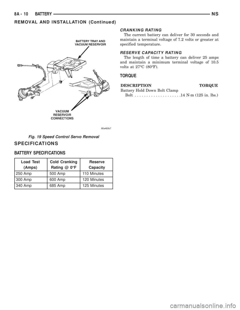
SPECIFICATIONS
BATTERY SPECIFICATIONS
CRANKING RATING
The current battery can deliver for 30 seconds and
maintain a terminal voltage of 7.2 volts or greater at
specified temperature.
RESERVE CAPACITY RATING
The length of time a battery can deliver 25 amps
and maintain a minimum terminal voltage of 10.5
volts at 27ÉC (80ÉF).
TORQUE
DESCRIPTION TORQUE
Battery Hold Down Bolt Clamp
Bolt....................14N´m(125 in. lbs.)
Fig. 19 Speed Control Servo Removal
Load Test
(Amps)Cold Cranking
Rating @ 0ÉFReserve
Capacity
250 Amp 500 Amp 110 Minutes
300 Amp 600 Amp 120 Minutes
340 Amp 685 Amp 125 Minutes
8A - 10 BATTERYNS
REMOVAL AND INSTALLATION (Continued)
Page 263 of 1938
BATTERY
CONTENTS
page page
GENERAL INFORMATION
INTRODUCTION........................ 1
SAFETY PRECAUTIONS AND WARNINGS.... 1
DESCRIPTION AND OPERATION
BATTERY IGNITION OFF DRAW (IOD)....... 2
CHARGING TIME REQUIRED.............. 2
DIAGNOSIS AND TESTING
BATTERY DISCHARGING................. 3
BATTERY IGNITION OFF DRAW............ 3
BATTERY LOAD TEST................... 5
BATTERY OPEN CIRCUIT VOLTAGE TEST.... 6SERVICE PROCEDURES
BATTERY CHARGING.................... 6
CHARGING COMPLETELY DISCHARGED
BATTERY............................ 7
VISUAL INSPECTION.................... 7
REMOVAL AND INSTALLATION
BATTERY............................. 8
BATTERY TRAY........................ 9
SPECIFICATIONS
BATTERY SPECIFICATIONS............... 9
TORQUE............................. 10
GENERAL INFORMATION
INTRODUCTION
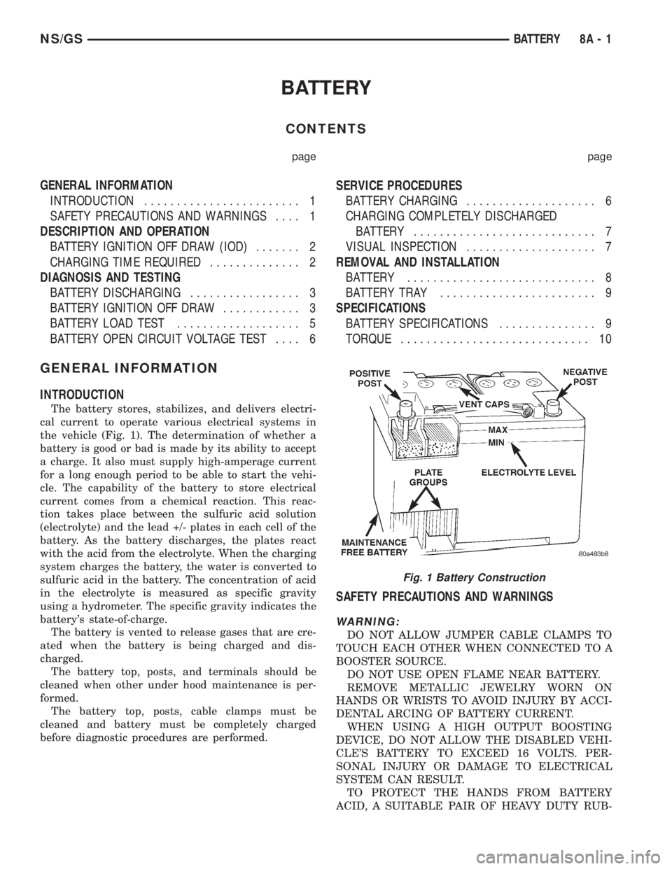
The battery stores, stabilizes, and delivers electri-
cal current to operate various electrical systems in
the vehicle (Fig. 1). The determination of whether a
battery is good or bad is made by its ability to accept
a charge. It also must supply high-amperage current
for a long enough period to be able to start the vehi-
cle. The capability of the battery to store electrical
current comes from a chemical reaction. This reac-
tion takes place between the sulfuric acid solution
(electrolyte) and the lead +/- plates in each cell of the
battery. As the battery discharges, the plates react
with the acid from the electrolyte. When the charging
system charges the battery, the water is converted to
sulfuric acid in the battery. The concentration of acid
in the electrolyte is measured as specific gravity
using a hydrometer. The specific gravity indicates the
battery's state-of-charge.
The battery is vented to release gases that are cre-
ated when the battery is being charged and dis-
charged.
The battery top, posts, and terminals should be
cleaned when other under hood maintenance is per-
formed.
The battery top, posts, cable clamps must be
cleaned and battery must be completely charged
before diagnostic procedures are performed.
SAFETY PRECAUTIONS AND WARNINGS
WARNING:
DO NOT ALLOW JUMPER CABLE CLAMPS TO
TOUCH EACH OTHER WHEN CONNECTED TO A
BOOSTER SOURCE.
DO NOT USE OPEN FLAME NEAR BATTERY.
REMOVE METALLIC JEWELRY WORN ON
HANDS OR WRISTS TO AVOID INJURY BY ACCI-
DENTAL ARCING OF BATTERY CURRENT.
WHEN USING A HIGH OUTPUT BOOSTING
DEVICE, DO NOT ALLOW THE DISABLED VEHI-
CLE'S BATTERY TO EXCEED 16 VOLTS. PER-
SONAL INJURY OR DAMAGE TO ELECTRICAL
SYSTEM CAN RESULT.
TO PROTECT THE HANDS FROM BATTERY
ACID, A SUITABLE PAIR OF HEAVY DUTY RUB-
Fig. 1 Battery Construction
NS/GSBATTERY 8A - 1
Page 272 of 1938
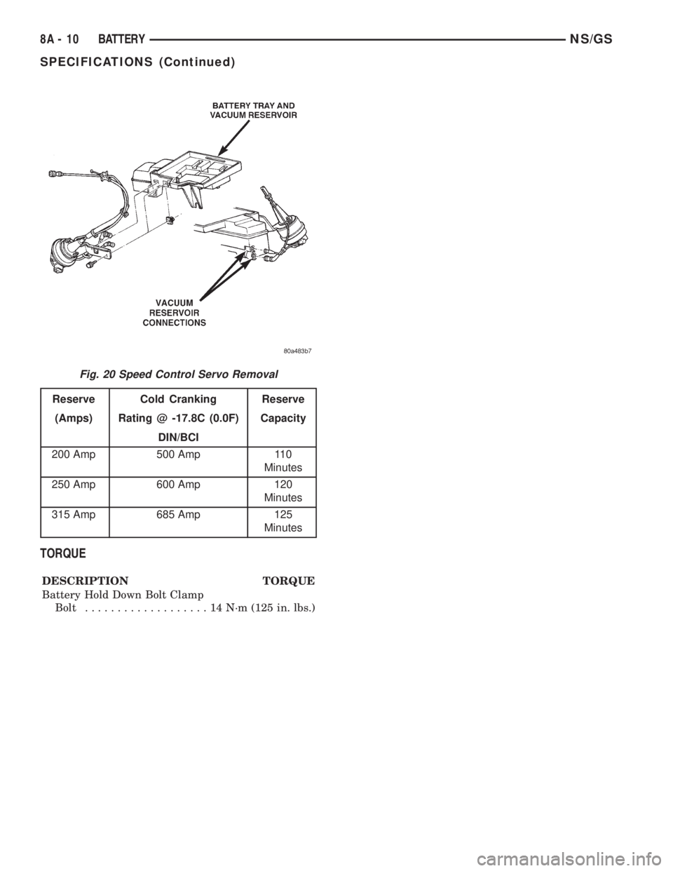
TORQUE
DESCRIPTION TORQUE
Battery Hold Down Bolt Clamp
Bolt...................14N´m(125 in. lbs.)
Fig. 20 Speed Control Servo Removal
Reserve Cold Cranking Reserve
(Amps) Rating @ -17.8C (0.0F) Capacity
DIN/BCI
200 Amp 500 Amp 110
Minutes
250 Amp 600 Amp 120
Minutes
315 Amp 685 Amp 125
Minutes
8A - 10 BATTERYNS/GS
SPECIFICATIONS (Continued)
Page 273 of 1938
STARTER
CONTENTS
page page
GENERAL INFORMATION
INTRODUCTION......................... 1
DESCRIPTION AND OPERATION
SUPPLY CIRCUIT AND CONTROL CIRCUIT.... 1
DIAGNOSIS AND TESTING
CONTROL CIRCUIT TEST.................. 1
FEED CIRCUIT RESISTANCE TEST........... 3
FEED CIRCUIT TEST...................... 4REMOVAL AND INSTALLATION
STARTERÐ2.4L ENGINE.................. 5
STARTERÐ3.0L ENGINE.................. 6
STARTERÐ3.3/3.8L ENGINE............... 6
SPECIFICATIONS
STARTER .............................. 7
TORQUE............................... 7
GENERAL INFORMATION
INTRODUCTION
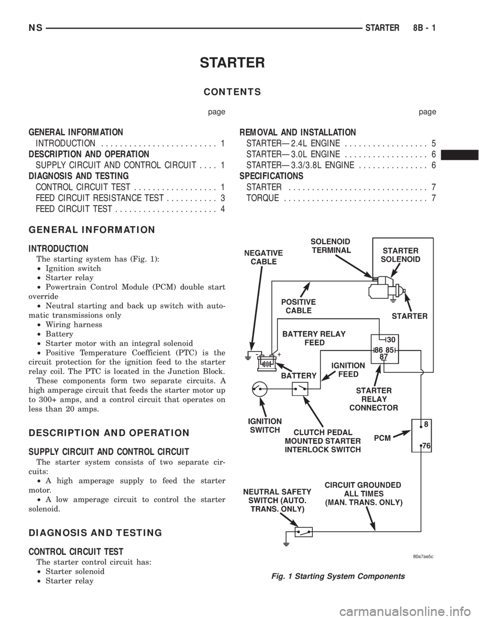
The starting system has (Fig. 1):
²Ignition switch
²Starter relay
²Powertrain Control Module (PCM) double start
override
²Neutral starting and back up switch with auto-
matic transmissions only
²Wiring harness
²Battery
²Starter motor with an integral solenoid
²Positive Temperature Coefficient (PTC) is the
circuit protection for the ignition feed to the starter
relay coil. The PTC is located in the Junction Block.
These components form two separate circuits. A
high amperage circuit that feeds the starter motor up
to 300+ amps, and a control circuit that operates on
less than 20 amps.
DESCRIPTION AND OPERATION
SUPPLY CIRCUIT AND CONTROL CIRCUIT
The starter system consists of two separate cir-
cuits:
²A high amperage supply to feed the starter
motor.
²A low amperage circuit to control the starter
solenoid.
DIAGNOSIS AND TESTING
CONTROL CIRCUIT TEST
The starter control circuit has:
²Starter solenoid
²Starter relay
Fig. 1 Starting System Components
NSSTARTER 8B - 1
Page 279 of 1938
(4) Connect solenoid connector into starter.
(5) Install nut to hold B+ terminal to starter sole-
noid.
(6) Lower vehicle.
(7) Connect battery negative cable.(8) Verify starter operation.
SPECIFICATIONS
STARTER
Engine should be up to operating temperature.
Extremely heavy oil or tight engine will increase
starter amperage draw.
TORQUE
DESCRIPTION TORQUE
Starter Mounting Bolts.........54N´m(40ft.lbs.)
Starter Solenoid Battery Nut. . . .10 N´m (90 in. lbs.)
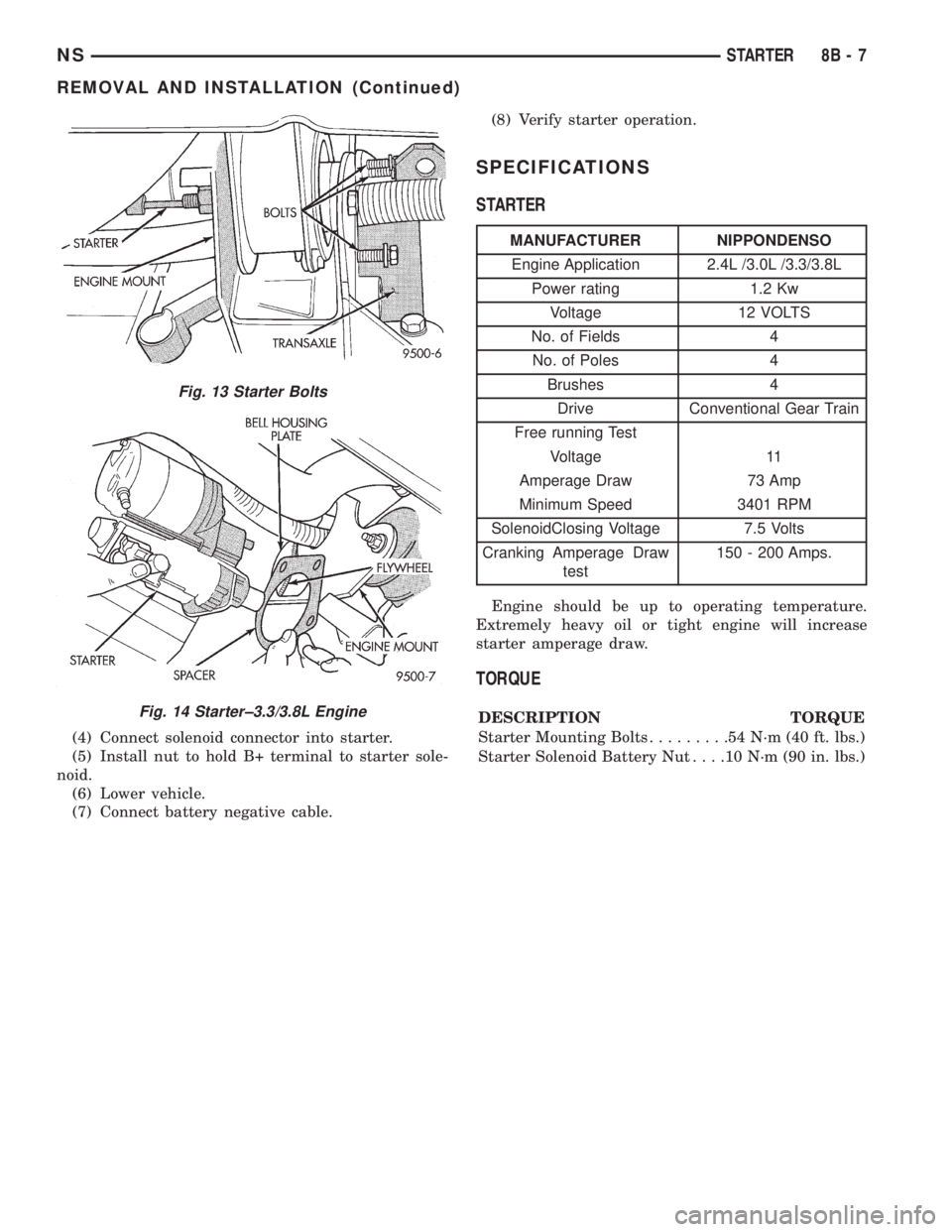
Fig. 13 Starter Bolts
Fig. 14 Starter±3.3/3.8L Engine
MANUFACTURER NIPPONDENSO
Engine Application 2.4L /3.0L /3.3/3.8L
Power rating 1.2 Kw
Voltage 12 VOLTS
No. of Fields 4
No. of Poles 4
Brushes 4
Drive Conventional Gear Train
Free running Test
Voltage 11
Amperage Draw 73 Amp
Minimum Speed 3401 RPM
SolenoidClosing Voltage 7.5 Volts
Cranking Amperage Draw
test150 - 200 Amps.
NSSTARTER 8B - 7
REMOVAL AND INSTALLATION (Continued)
Page 281 of 1938
STARTING SYSTEM
CONTENTS
page
REMOVAL AND INSTALLATION
STARTER ............................. 1
REMOVAL AND INSTALLATION
STARTER
2.0L ENGINE
REMOVAL
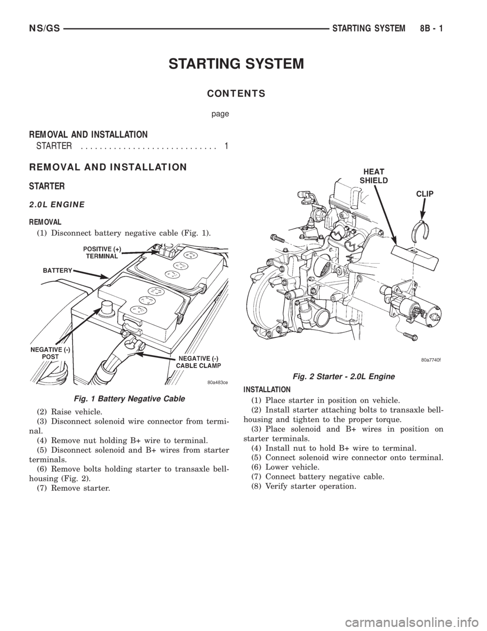
(1) Disconnect battery negative cable (Fig. 1).
(2) Raise vehicle.
(3) Disconnect solenoid wire connector from termi-
nal.
(4) Remove nut holding B+ wire to terminal.
(5) Disconnect solenoid and B+ wires from starter
terminals.
(6) Remove bolts holding starter to transaxle bell-
housing (Fig. 2).
(7) Remove starter.INSTALLATION
(1) Place starter in position on vehicle.
(2) Install starter attaching bolts to transaxle bell-
housing and tighten to the proper torque.
(3) Place solenoid and B+ wires in position on
starter terminals.
(4) Install nut to hold B+ wire to terminal.
(5) Connect solenoid wire connector onto terminal.
(6) Lower vehicle.
(7) Connect battery negative cable.
(8) Verify starter operation.
Fig. 1 Battery Negative Cable
Fig. 2 Starter - 2.0L Engine
NS/GSSTARTING SYSTEM 8B - 1
Page 282 of 1938
2.4L ENGINE - With Manual Transaxle
REMOVAL
(1) Release hood latch and open hood.
(2) Disconnect battery negative cable (Fig. 1).
(3) Hoist and support vehicle on safety stands.
(4) Disconnect solenoid wire connector from termi-
nal.
(5) Remove nut holding B+ wire to terminal.
(6) Disconnect solenoid and B+ wires from starter
terminals.
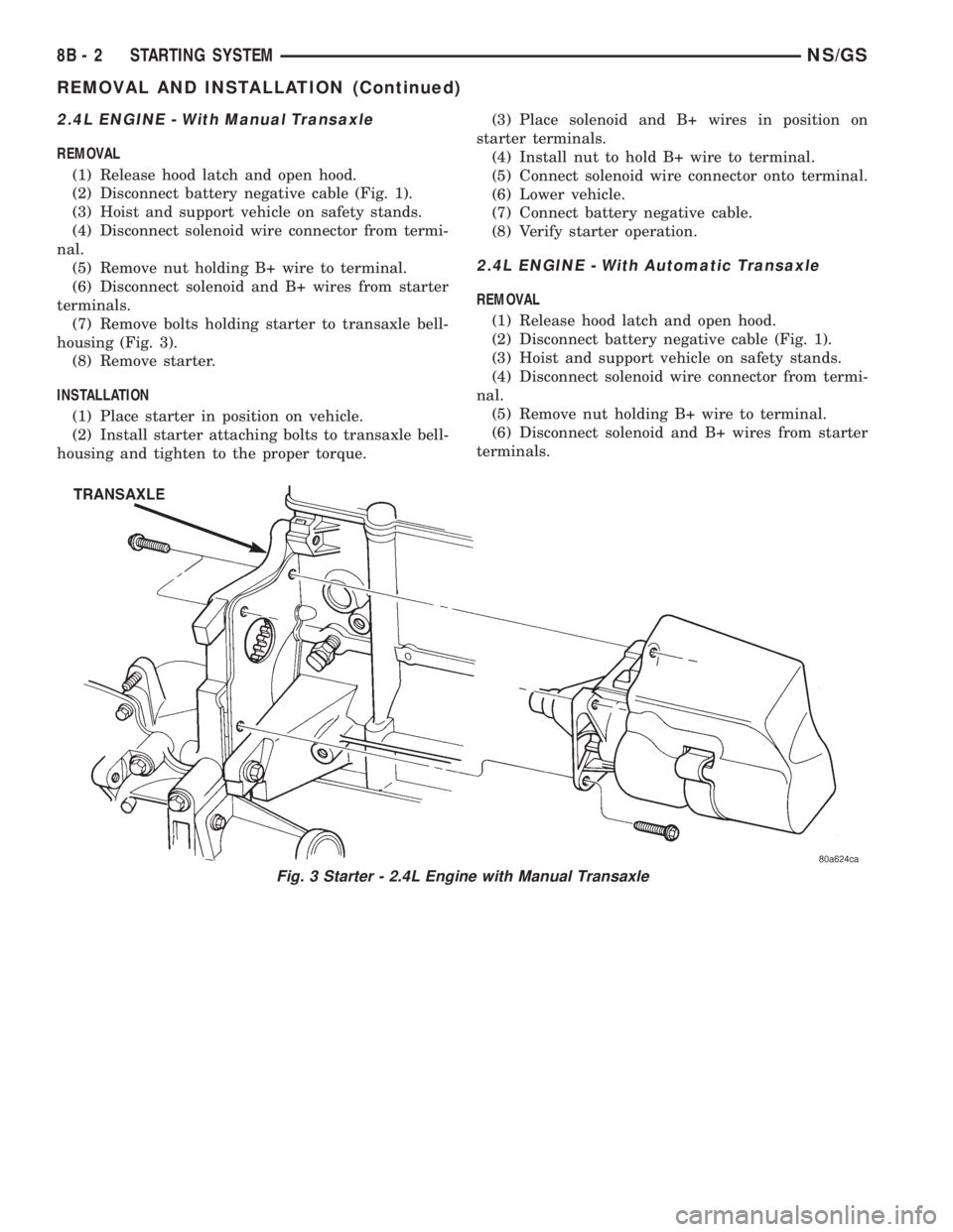
(7) Remove bolts holding starter to transaxle bell-
housing (Fig. 3).
(8) Remove starter.
INSTALLATION
(1) Place starter in position on vehicle.
(2) Install starter attaching bolts to transaxle bell-
housing and tighten to the proper torque.(3) Place solenoid and B+ wires in position on
starter terminals.
(4) Install nut to hold B+ wire to terminal.
(5) Connect solenoid wire connector onto terminal.
(6) Lower vehicle.
(7) Connect battery negative cable.
(8) Verify starter operation.
2.4L ENGINE - With Automatic Transaxle
REMOVAL
(1) Release hood latch and open hood.
(2) Disconnect battery negative cable (Fig. 1).
(3) Hoist and support vehicle on safety stands.
(4) Disconnect solenoid wire connector from termi-
nal.
(5) Remove nut holding B+ wire to terminal.
(6) Disconnect solenoid and B+ wires from starter
terminals.
Fig. 3 Starter - 2.4L Engine with Manual Transaxle
8B - 2 STARTING SYSTEMNS/GS
REMOVAL AND INSTALLATION (Continued)
Page 283 of 1938
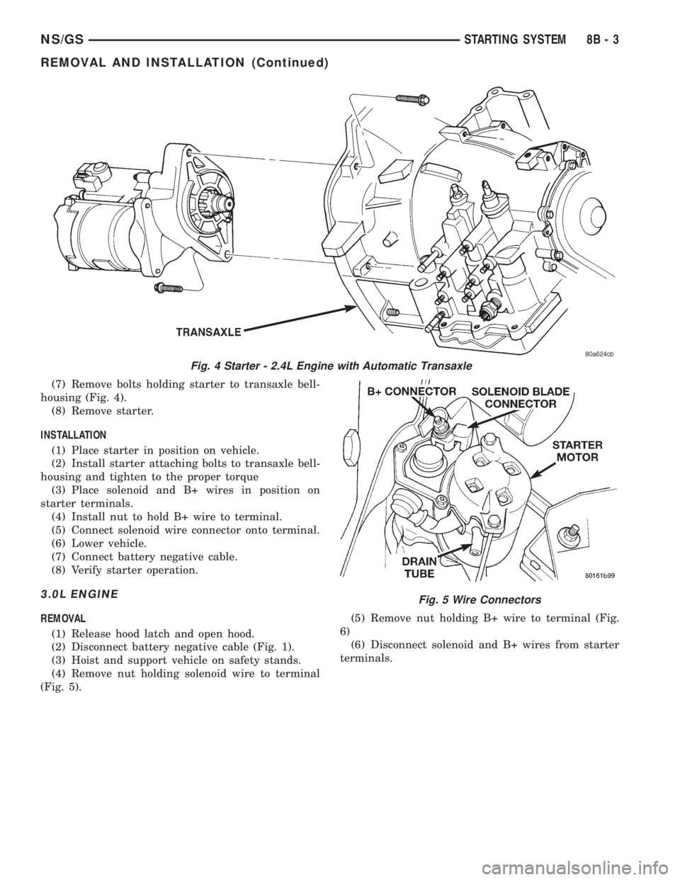
(7) Remove bolts holding starter to transaxle bell-
housing (Fig. 4).
(8) Remove starter.
INSTALLATION
(1) Place starter in position on vehicle.
(2) Install starter attaching bolts to transaxle bell-
housing and tighten to the proper torque
(3) Place solenoid and B+ wires in position on
starter terminals.
(4) Install nut to hold B+ wire to terminal.
(5) Connect solenoid wire connector onto terminal.
(6) Lower vehicle.
(7) Connect battery negative cable.
(8) Verify starter operation.
3.0L ENGINE
REMOVAL
(1) Release hood latch and open hood.
(2) Disconnect battery negative cable (Fig. 1).
(3) Hoist and support vehicle on safety stands.
(4) Remove nut holding solenoid wire to terminal
(Fig. 5).(5) Remove nut holding B+ wire to terminal (Fig.
6)
(6) Disconnect solenoid and B+ wires from starter
terminals.
Fig. 4 Starter - 2.4L Engine with Automatic Transaxle
Fig. 5 Wire Connectors
NS/GSSTARTING SYSTEM 8B - 3
REMOVAL AND INSTALLATION (Continued)