CHRYSLER VOYAGER 1996 Service Manual
Manufacturer: CHRYSLER, Model Year: 1996, Model line: VOYAGER, Model: CHRYSLER VOYAGER 1996Pages: 1938, PDF Size: 55.84 MB
Page 151 of 1938
(4) Insert cable housing retainer into body outrig-
ger bracket making certain that cable housing
retainer fingers lock the housing firmly into place.
(5) Connect rear park brake cable to the equalizer
bracket (Fig. 169).
(6) Install brake drum, and wheel and tire assem-
bly.
(7) Remove the locking pliers from the front park
brake cable. This will automatically adjust the park
brake cables.
(8) Apply and release park brake pedal 1 time,
this will seat the park brake cables.
STOP LAMP SWITCH
REMOVE
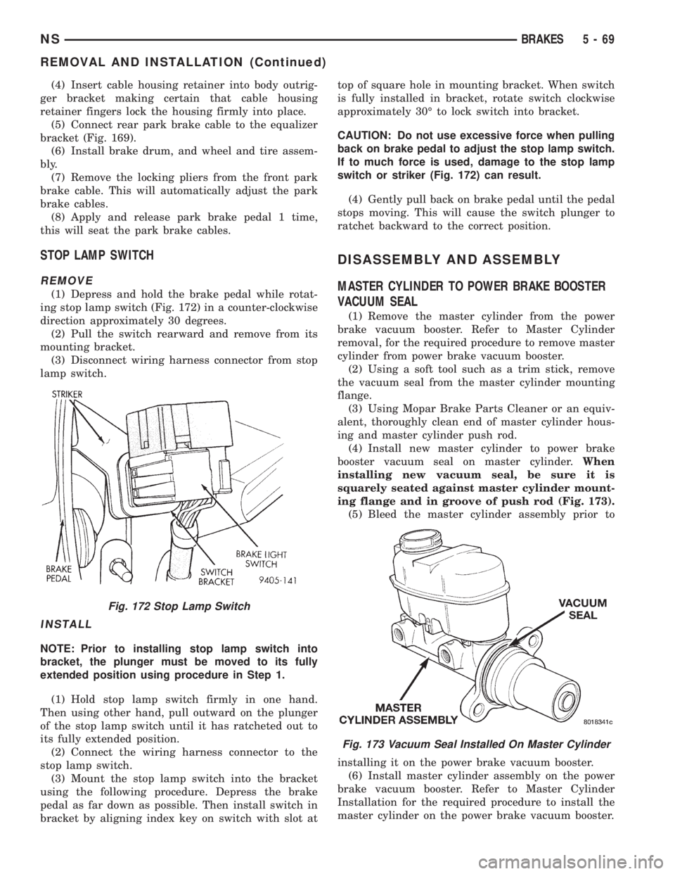
(1) Depress and hold the brake pedal while rotat-
ing stop lamp switch (Fig. 172) in a counter-clockwise
direction approximately 30 degrees.
(2) Pull the switch rearward and remove from its
mounting bracket.
(3) Disconnect wiring harness connector from stop
lamp switch.
INSTALL
NOTE: Prior to installing stop lamp switch into
bracket, the plunger must be moved to its fully
extended position using procedure in Step 1.
(1) Hold stop lamp switch firmly in one hand.
Then using other hand, pull outward on the plunger
of the stop lamp switch until it has ratcheted out to
its fully extended position.
(2) Connect the wiring harness connector to the
stop lamp switch.
(3) Mount the stop lamp switch into the bracket
using the following procedure. Depress the brake
pedal as far down as possible. Then install switch in
bracket by aligning index key on switch with slot attop of square hole in mounting bracket. When switch
is fully installed in bracket, rotate switch clockwise
approximately 30É to lock switch into bracket.
CAUTION: Do not use excessive force when pulling
back on brake pedal to adjust the stop lamp switch.
If to much force is used, damage to the stop lamp
switch or striker (Fig. 172) can result.
(4) Gently pull back on brake pedal until the pedal
stops moving. This will cause the switch plunger to
ratchet backward to the correct position.
DISASSEMBLY AND ASSEMBLY
MASTER CYLINDER TO POWER BRAKE BOOSTER
VACUUM SEAL
(1) Remove the master cylinder from the power
brake vacuum booster. Refer to Master Cylinder
removal, for the required procedure to remove master
cylinder from power brake vacuum booster.
(2) Using a soft tool such as a trim stick, remove
the vacuum seal from the master cylinder mounting
flange.
(3) Using Mopar Brake Parts Cleaner or an equiv-
alent, thoroughly clean end of master cylinder hous-
ing and master cylinder push rod.
(4) Install new master cylinder to power brake
booster vacuum seal on master cylinder.When
installing new vacuum seal, be sure it is
squarely seated against master cylinder mount-
ing flange and in groove of push rod (Fig. 173).
(5) Bleed the master cylinder assembly prior to
installing it on the power brake vacuum booster.
(6) Install master cylinder assembly on the power
brake vacuum booster. Refer to Master Cylinder
Installation for the required procedure to install the
master cylinder on the power brake vacuum booster.
Fig. 172 Stop Lamp Switch
Fig. 173 Vacuum Seal Installed On Master Cylinder
NSBRAKES 5 - 69
REMOVAL AND INSTALLATION (Continued)
Page 152 of 1938
(7) Road test vehicle to ensure proper operation of
the vehicle's power brake system.
MASTER CYLINDER FLUID RESERVOIR
(1) Clean master cylinder housing and brake fluid
reservoir. Use only a solvent such as Mopar Brake
Parts Cleaner or an equivalent.
(2) Remove the filler tube and brake fluid reser-
voir cap. Using a syringe or equivalent type tool
empty as much brake fluid as possible from the res-
ervoir.
CAUTION: When removing fluid reservoir from the
master cylinder, do not pry off using any type of
tool. This can damage the fluid reservoir or master
cylinder housing.
(3) Remove the master cylinder assembly from the
power brake vacuum booster. Refer to master cylin-
der, in the removal and installation section in this
group of the service manual for the required proce-
dure
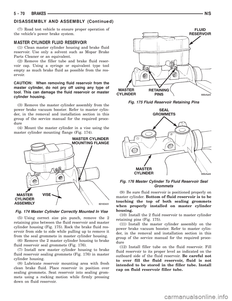
(4) Mount the master cylinder in a vise using the
master cylinder mounting flange (Fig. 174).
(5) Using correct size pin punch, remove the 2
retaining pins between the fluid reservoir and master
cylinder housing (Fig. 175). Rock the brake fluid res-
ervoir from side to side while pulling up to remove it
from the seal grommets in master cylinder housing.
(6) Remove the 2 master cylinder housing to brake
fluid reservoir seal grommets (Fig. 176).
(7) Install new master cylinder housing to brake
fluid reservoir sealing grommets (Fig. 176) in master
cylinder housing.
(8) Lubricate reservoir mounting area with fresh
clean brake fluid. Place reservoir in position over
sealing grommets. Seat reservoir into sealing grom-
mets using a rocking motion while firmly pressing
down on fluid reservoir.(9) Be sure fluid reservoir is positioned properly on
master cylinder.Bottom of fluid reservoir is to be
touching the top of both sealing grommets
when properly installed on master cylinder
housing.
(10) Install the 2 fluid reservoir to master cylinder
retaining pins (Fig. 175).
(11) Install the master cylinder assembly on the
power brake vacuum booster. Refer to master cylin-
der, in the removal and installation section in this
group of the service manual for the required proce-
dure
(12) Install filler tube on the fluid reservoir. Fill
fluid reservoir to its proper level as indicated on the
outboard side of the fluid reservoir.Be careful not
to over fill the fluid reservoir, fluid is not
intended to be stored in the filler tube. Install
cap on fluid reservoir filler tube.
Fig. 174 Master Cylinder Correctly Mounted In Vise
Fig. 175 Fluid Reservoir Retaining Pins
Fig. 176 Master Cylinder To Fluid Reservoir Seal
Grommets
5 - 70 BRAKESNS
DISASSEMBLY AND ASSEMBLY (Continued)
Page 153 of 1938
MASTER CYLINDER FLUID RESERVOIR FILL TUBE
The master cylinder fluid reservoir filler neck is
removable from the master cylinder fluid reservoir.
The filler neck if required, can be replaced as a sep-
arate component of the fluid reservoir.
The filler neck is removed and installed using the
following procedure.
REMOVE
(1) Check brake fluid level in master cylinder fluid
reservoir to be sure brake fluid is not in the filler
neck. If brake fluid is in filler neck, lower fluid level
before removing filler neck from fluid reservoir
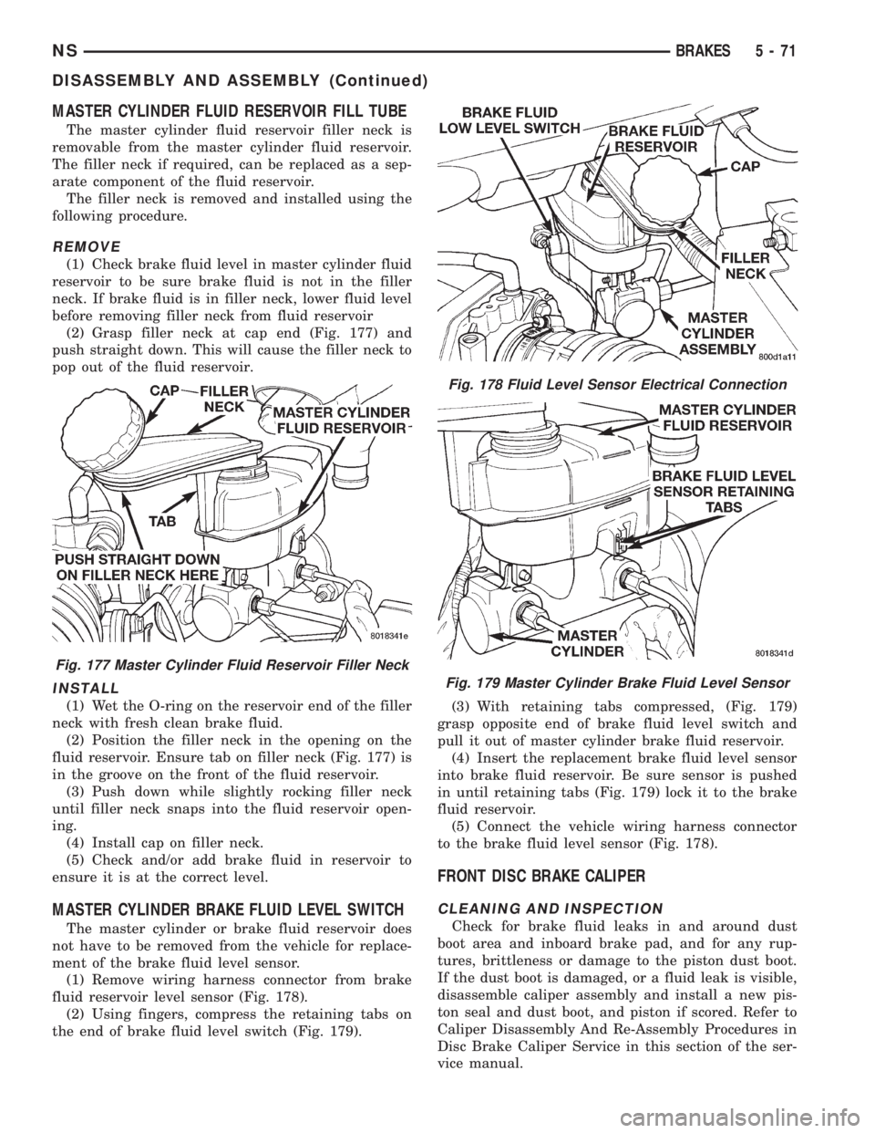
(2) Grasp filler neck at cap end (Fig. 177) and
push straight down. This will cause the filler neck to
pop out of the fluid reservoir.
INSTALL
(1) Wet the O-ring on the reservoir end of the filler
neck with fresh clean brake fluid.
(2) Position the filler neck in the opening on the
fluid reservoir. Ensure tab on filler neck (Fig. 177) is
in the groove on the front of the fluid reservoir.
(3) Push down while slightly rocking filler neck
until filler neck snaps into the fluid reservoir open-
ing.
(4) Install cap on filler neck.
(5) Check and/or add brake fluid in reservoir to
ensure it is at the correct level.
MASTER CYLINDER BRAKE FLUID LEVEL SWITCH
The master cylinder or brake fluid reservoir does
not have to be removed from the vehicle for replace-
ment of the brake fluid level sensor.
(1) Remove wiring harness connector from brake
fluid reservoir level sensor (Fig. 178).
(2) Using fingers, compress the retaining tabs on
the end of brake fluid level switch (Fig. 179).(3) With retaining tabs compressed, (Fig. 179)
grasp opposite end of brake fluid level switch and
pull it out of master cylinder brake fluid reservoir.
(4) Insert the replacement brake fluid level sensor
into brake fluid reservoir. Be sure sensor is pushed
in until retaining tabs (Fig. 179) lock it to the brake
fluid reservoir.
(5) Connect the vehicle wiring harness connector
to the brake fluid level sensor (Fig. 178).
FRONT DISC BRAKE CALIPER
CLEANING AND INSPECTION
Check for brake fluid leaks in and around dust
boot area and inboard brake pad, and for any rup-
tures, brittleness or damage to the piston dust boot.
If the dust boot is damaged, or a fluid leak is visible,
disassemble caliper assembly and install a new pis-
ton seal and dust boot, and piston if scored. Refer to
Caliper Disassembly And Re-Assembly Procedures in
Disc Brake Caliper Service in this section of the ser-
vice manual.
Fig. 177 Master Cylinder Fluid Reservoir Filler Neck
Fig. 178 Fluid Level Sensor Electrical Connection
Fig. 179 Master Cylinder Brake Fluid Level Sensor
NSBRAKES 5 - 71
DISASSEMBLY AND ASSEMBLY (Continued)
Page 154 of 1938
Check the guide pin dust boots to determine if they
are in good condition. Replace if they are damaged,
dry, or found to be brittle. Refer to Guide Pin Bush-
ing Service in Disc Brake Caliper Service in this sec-
tion of the service manual.
CALIPER GUIDE PIN BUSHING SERVICE
The double pin caliper uses a sealed for life bush-
ing and sleeve assembly. If required this assembly
can be serviced using the following procedure.
REMOVING CALIPER GUIDE PIN BUSHINGS
(1) Remove caliper from brake rotor (See Brake
Shoe Removal). Hang caliper assembly on a wire
hook away from the brake rotor.
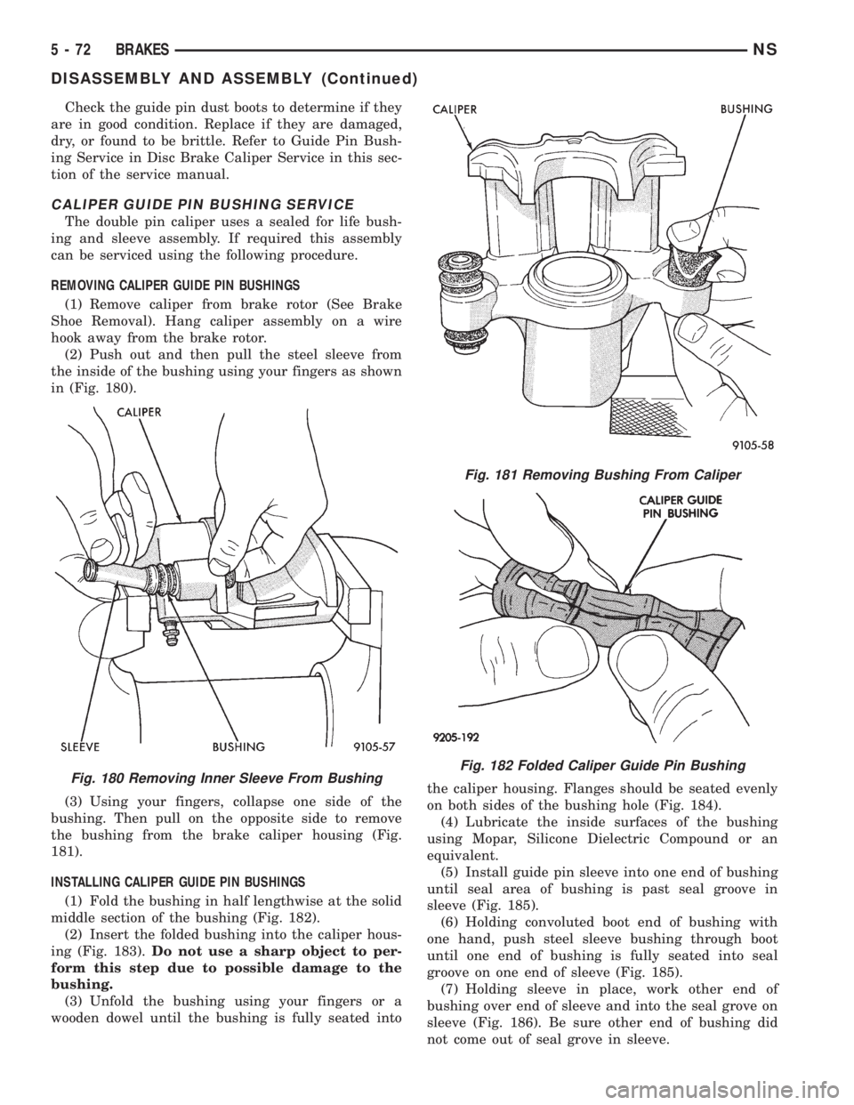
(2) Push out and then pull the steel sleeve from
the inside of the bushing using your fingers as shown
in (Fig. 180).
(3) Using your fingers, collapse one side of the
bushing. Then pull on the opposite side to remove
the bushing from the brake caliper housing (Fig.
181).
INSTALLING CALIPER GUIDE PIN BUSHINGS
(1) Fold the bushing in half lengthwise at the solid
middle section of the bushing (Fig. 182).
(2) Insert the folded bushing into the caliper hous-
ing (Fig. 183).Do not use a sharp object to per-
form this step due to possible damage to the
bushing.
(3) Unfold the bushing using your fingers or a
wooden dowel until the bushing is fully seated intothe caliper housing. Flanges should be seated evenly
on both sides of the bushing hole (Fig. 184).
(4) Lubricate the inside surfaces of the bushing
using Mopar, Silicone Dielectric Compound or an
equivalent.
(5) Install guide pin sleeve into one end of bushing
until seal area of bushing is past seal groove in
sleeve (Fig. 185).
(6) Holding convoluted boot end of bushing with
one hand, push steel sleeve bushing through boot
until one end of bushing is fully seated into seal
groove on one end of sleeve (Fig. 185).
(7) Holding sleeve in place, work other end of
bushing over end of sleeve and into the seal grove on
sleeve (Fig. 186). Be sure other end of bushing did
not come out of seal grove in sleeve.
Fig. 180 Removing Inner Sleeve From Bushing
Fig. 181 Removing Bushing From Caliper
Fig. 182 Folded Caliper Guide Pin Bushing
5 - 72 BRAKESNS
DISASSEMBLY AND ASSEMBLY (Continued)
Page 155 of 1938
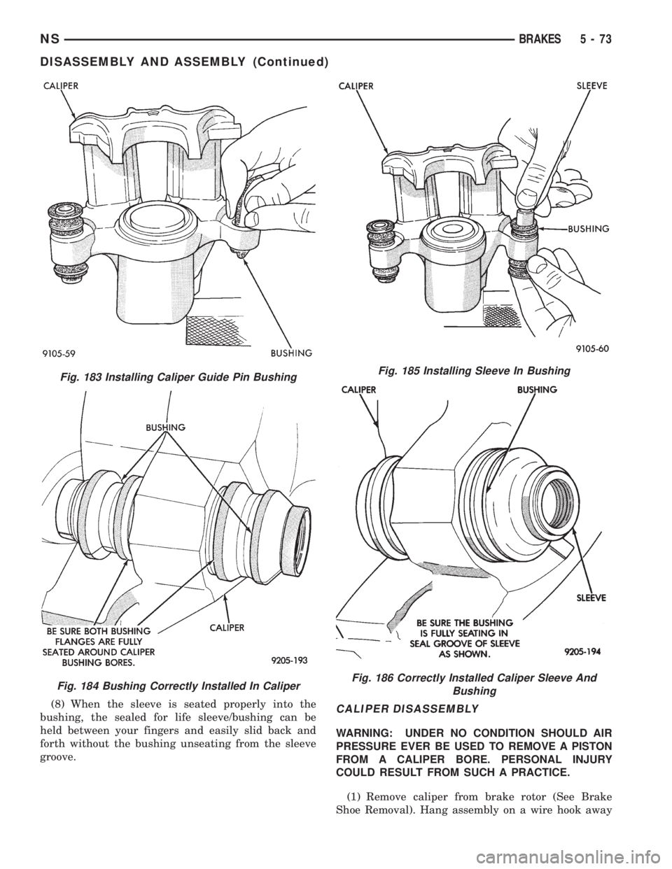
(8) When the sleeve is seated properly into the
bushing, the sealed for life sleeve/bushing can be
held between your fingers and easily slid back and
forth without the bushing unseating from the sleeve
groove.CALIPER DISASSEMBLY
WARNING: UNDER NO CONDITION SHOULD AIR
PRESSURE EVER BE USED TO REMOVE A PISTON
FROM A CALIPER BORE. PERSONAL INJURY
COULD RESULT FROM SUCH A PRACTICE.
(1) Remove caliper from brake rotor (See Brake
Shoe Removal). Hang assembly on a wire hook away
Fig. 183 Installing Caliper Guide Pin Bushing
Fig. 184 Bushing Correctly Installed In Caliper
Fig. 185 Installing Sleeve In Bushing
Fig. 186 Correctly Installed Caliper Sleeve And
Bushing
NSBRAKES 5 - 73
DISASSEMBLY AND ASSEMBLY (Continued)
Page 156 of 1938
from rotor, so hydraulic fluid cannot get on rotor.
Place a small piece of wood between the piston and
caliper fingers.
(2)Carefullydepress brake pedal to hydraulically
push piston out of bore. Then apply and hold down
the brake pedal to any position beyond the first inch
of pedal travel. This will prevent loss of brake fluid
from the master cylinder.
(3) If both front caliper pistons are to be removed,
disconnect brake tube at flexible brake hose at frame
rail. Plug brake tube and remove piston from oppo-
site caliper using the same process as above for the
first piston removal.
(4) Disconnect the brake fluid flex hose from the
caliper assembly.
CAUTION: Do not use excessive force when clamp-
ing caliper in vise. Excessive vise pressure will
cause bore distortion and binding of piston.
(5) To disassemble caliper, mount in a vise
equipped with protective jaws.
(6) Remove guide pin sleeves and guide pin bush-
ings. See Removing Guide Pin Bushings in the cali-
per disassembly section of this manual.
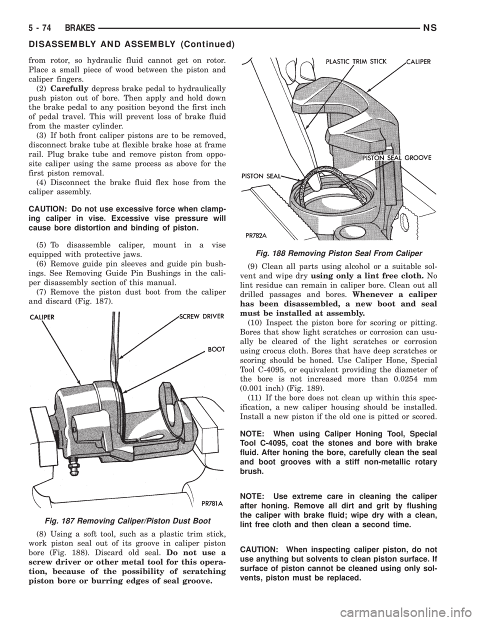
(7) Remove the piston dust boot from the caliper
and discard (Fig. 187).
(8) Using a soft tool, such as a plastic trim stick,
work piston seal out of its groove in caliper piston
bore (Fig. 188). Discard old seal.Do not use a
screw driver or other metal tool for this opera-
tion, because of the possibility of scratching
piston bore or burring edges of seal groove.(9) Clean all parts using alcohol or a suitable sol-
vent and wipe dryusing only a lint free cloth.No
lint residue can remain in caliper bore. Clean out all
drilled passages and bores.Whenever a caliper
has been disassembled, a new boot and seal
must be installed at assembly.
(10) Inspect the piston bore for scoring or pitting.
Bores that show light scratches or corrosion can usu-
ally be cleared of the light scratches or corrosion
using crocus cloth. Bores that have deep scratches or
scoring should be honed. Use Caliper Hone, Special
Tool C-4095, or equivalent providing the diameter of
the bore is not increased more than 0.0254 mm
(0.001 inch) (Fig. 189).
(11) If the bore does not clean up within this spec-
ification, a new caliper housing should be installed.
Install a new piston if the old one is pitted or scored.
NOTE: When using Caliper Honing Tool, Special
Tool C-4095, coat the stones and bore with brake
fluid. After honing the bore, carefully clean the seal
and boot grooves with a stiff non-metallic rotary
brush.
NOTE: Use extreme care in cleaning the caliper
after honing. Remove all dirt and grit by flushing
the caliper with brake fluid; wipe dry with a clean,
lint free cloth and then clean a second time.
CAUTION: When inspecting caliper piston, do not
use anything but solvents to clean piston surface. If
surface of piston cannot be cleaned using only sol-
vents, piston must be replaced.
Fig. 187 Removing Caliper/Piston Dust Boot
Fig. 188 Removing Piston Seal From Caliper
5 - 74 BRAKESNS
DISASSEMBLY AND ASSEMBLY (Continued)
Page 157 of 1938
(12) Inspect caliper piston for pitting, scratches, or
any physical damage. Replace piston if there is evi-
dence of scratches, pitting or physical damage.
CALIPER ASSEMBLY
CAUTION: Excessive vise pressure will cause bore
distortion and binding of piston.
(1) Clamp caliper in a vise (with protective caps
installed on jaws of vise).
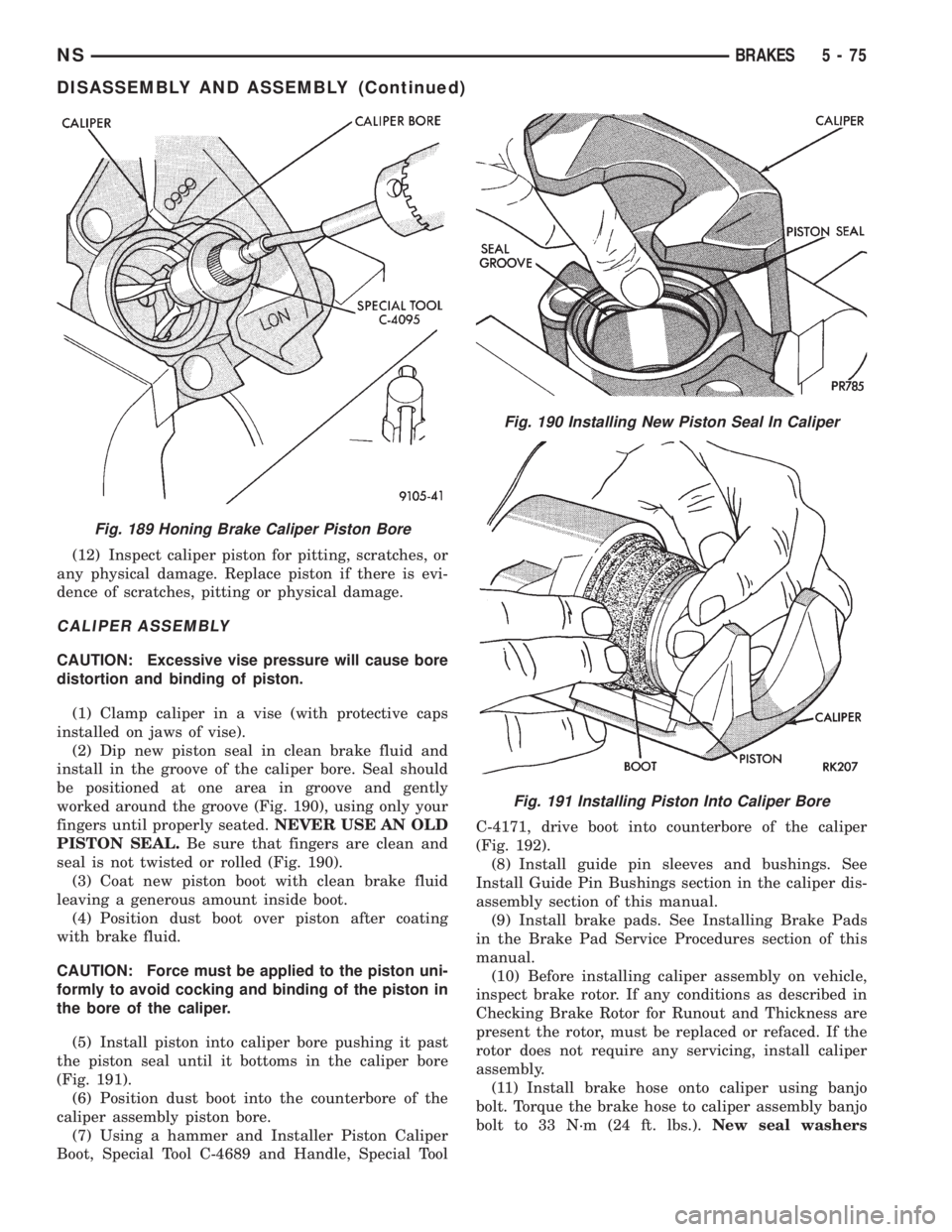
(2) Dip new piston seal in clean brake fluid and
install in the groove of the caliper bore. Seal should
be positioned at one area in groove and gently
worked around the groove (Fig. 190), using only your
fingers until properly seated.NEVER USE AN OLD
PISTON SEAL.Be sure that fingers are clean and
seal is not twisted or rolled (Fig. 190).
(3) Coat new piston boot with clean brake fluid
leaving a generous amount inside boot.
(4) Position dust boot over piston after coating
with brake fluid.
CAUTION: Force must be applied to the piston uni-
formly to avoid cocking and binding of the piston in
the bore of the caliper.
(5) Install piston into caliper bore pushing it past
the piston seal until it bottoms in the caliper bore
(Fig. 191).
(6) Position dust boot into the counterbore of the
caliper assembly piston bore.
(7) Using a hammer and Installer Piston Caliper
Boot, Special Tool C-4689 and Handle, Special ToolC-4171, drive boot into counterbore of the caliper
(Fig. 192).
(8) Install guide pin sleeves and bushings. See
Install Guide Pin Bushings section in the caliper dis-
assembly section of this manual.
(9) Install brake pads. See Installing Brake Pads
in the Brake Pad Service Procedures section of this
manual.
(10) Before installing caliper assembly on vehicle,
inspect brake rotor. If any conditions as described in
Checking Brake Rotor for Runout and Thickness are
present the rotor, must be replaced or refaced. If the
rotor does not require any servicing, install caliper
assembly.
(11) Install brake hose onto caliper using banjo
bolt. Torque the brake hose to caliper assembly banjo
bolt to 33 N´m (24 ft. lbs.).New seal washers
Fig. 189 Honing Brake Caliper Piston Bore
Fig. 190 Installing New Piston Seal In Caliper
Fig. 191 Installing Piston Into Caliper Bore
NSBRAKES 5 - 75
DISASSEMBLY AND ASSEMBLY (Continued)
Page 158 of 1938
MUST always be used when installing brake
hose to caliper.
(12) Bleed the brake system (see Bleeding Brake
System).
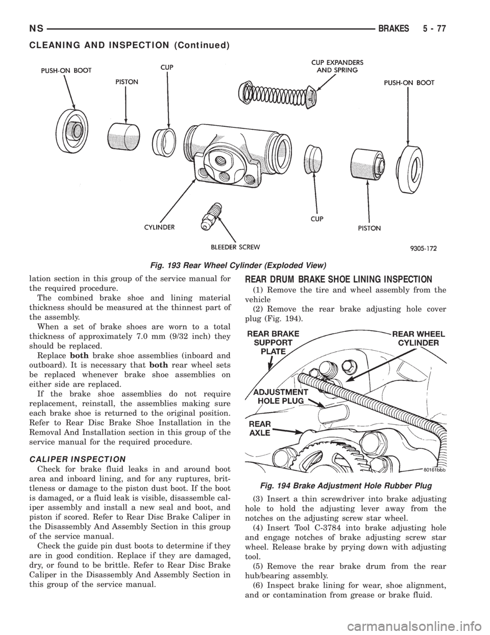
WHEEL CYLINDER REAR DRUM BRAKE
DISASSEMBLE
To disassemble the wheel cylinders, proceed as fol-
lows:
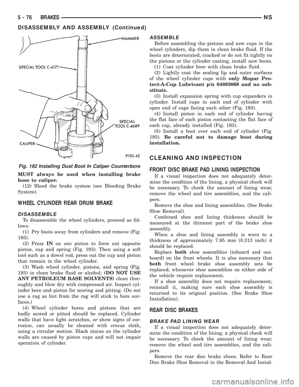
(1) Pry boots away from cylinders and remove (Fig.
193).
(2) PressINon one piston to force out opposite
piston, cup and spring (Fig. 193). Then using a soft
tool such as a dowel rod, press out the cup and piston
that remain in the wheel cylinder.
(3) Wash wheel cylinder, pistons, and spring (Fig.
193) in clean brake fluid or alcohol;(DO NOT USE
ANY PETROLEUM BASE SOLVENTS)clean thor-
oughly and blow dry with compressed air. Inspect cyl-
inder bore and piston for scoring and pitting. (Do not
use a rag as lint from the rag will stick to bore sur-
faces.)
(4) Wheel cylinder bores and pistons that are
badly scored or pitted should be replaced. Cylinder
walls that have light scratches, or show signs of cor-
rosion, can usually be cleaned with crocus cloth,
using a circular motion. Black stains on the cylinder
walls are caused by piston cups and will not impair
operation of cylinder.
ASSEMBLE
Before assembling the pistons and new cups in the
wheel cylinders, dip them in clean brake fluid. If the
boots are deteriorated, cracked or do not fit tightly on
the pistons or the cylinder casting, install new boots.
(1) Coat cylinder bore with clean brake fluid.
(2) Lightly coat the sealing lip and outer surfaces
of the wheel cylinder cups withonly Mopar Pro-
tect-A-Cup Lubricant p/n 04883068 and no sub-
stitute.
(3) Install expansion spring with cup expanders in
cylinder. Install cups in each end of cylinder with
open end of cups facing each other (Fig. 193).
(4) Install piston in each end of cylinder having
the flat face of each piston contacting the flat face of
each cup, already installed (Fig. 193).
(5) Install a boot over each end of cylinder (Fig.
193).Be careful not to damage boot during
installation.
CLEANING AND INSPECTION
FRONT DISC BRAKE PAD LINING INSPECTION
If a visual inspection does not adequately deter-
mine the condition of the lining, a physical check will
be necessary. To check the amount of lining wear,
remove the wheel and tire assemblies, and the cali-
pers.
Remove the shoe and lining assemblies. (See Brake
Shoe Removal).
Combined shoe and lining thickness should be
measured at the thinnest part of the brake shoe
assembly.
When a shoe and lining assembly is worn to a
thickness of approximately 7.95 mm (0.313 inch) it
should be replaced.
Replacebothshoe assemblies (inboard and out-
board) on the front wheels. It is also necessary that
bothfront wheel brake shoe assembly sets be
replaced, whenever shoe assemblies on either side of
the vehicle require replacement.
If a shoe assembly does not require replacement,
reinstall it, making sure each shoe assembly is
returned to its original position. (See Brake Shoe
Installation).
REAR DISC BRAKES
BRAKE PAD LINING WEAR
If a visual inspection does not adequately deter-
mine the condition of the lining, a physical check will
be necessary. To check the amount of lining wear,
remove the wheel and tire assemblies, and the cali-
pers.
Remove the rear disc brake shoes. Refer to Rear
Disc Brake Shoe Removal in the Removal And Instal-
Fig. 192 Installing Dust Boot In Caliper Counterbore
5 - 76 BRAKESNS
DISASSEMBLY AND ASSEMBLY (Continued)
Page 159 of 1938
lation section in this group of the service manual for
the required procedure.
The combined brake shoe and lining material
thickness should be measured at the thinnest part of
the assembly.
When a set of brake shoes are worn to a total
thickness of approximately 7.0 mm (9/32 inch) they
should be replaced.
Replacebothbrake shoe assemblies (inboard and
outboard). It is necessary thatbothrear wheel sets
be replaced whenever brake shoe assemblies on
either side are replaced.
If the brake shoe assemblies do not require
replacement, reinstall, the assemblies making sure
each brake shoe is returned to the original position.
Refer to Rear Disc Brake Shoe Installation in the
Removal And Installation section in this group of the
service manual for the required procedure.
CALIPER INSPECTION
Check for brake fluid leaks in and around boot
area and inboard lining, and for any ruptures, brit-
tleness or damage to the piston dust boot. If the boot
is damaged, or a fluid leak is visible, disassemble cal-
iper assembly and install a new seal and boot, and
piston if scored. Refer to Rear Disc Brake Caliper in
the Disassembly And Assembly Section in this group
of the service manual.
Check the guide pin dust boots to determine if they
are in good condition. Replace if they are damaged,
dry, or found to be brittle. Refer to Rear Disc Brake
Caliper in the Disassembly And Assembly Section in
this group of the service manual.
REAR DRUM BRAKE SHOE LINING INSPECTION
(1) Remove the tire and wheel assembly from the
vehicle
(2) Remove the rear brake adjusting hole cover
plug (Fig. 194).
(3) Insert a thin screwdriver into brake adjusting
hole to hold the adjusting lever away from the
notches on the adjusting screw star wheel.
(4) Insert Tool C-3784 into brake adjusting hole
and engage notches of brake adjusting screw star
wheel. Release brake by prying down with adjusting
tool.
(5) Remove the rear brake drum from the rear
hub/bearing assembly.
(6) Inspect brake lining for wear, shoe alignment,
and or contamination from grease or brake fluid.
Fig. 193 Rear Wheel Cylinder (Exploded View)
Fig. 194 Brake Adjustment Hole Rubber Plug
NSBRAKES 5 - 77
CLEANING AND INSPECTION (Continued)
Page 160 of 1938
REAR DRUM BRAKE WHEEL CYLINDER
With brake drums removed, inspect the wheel cyl-
inder boots for evidence of a brake fluid leak. Visu-
ally check the boots for cuts, tears, or heat cracks. If
any of these conditions exist, the wheel cylinders
should be completely cleaned, inspected and new
parts installed.
If a wheel cylinder is leaking and the brake lining
material is saturated with brake fluid, the brake
shoes must be replaced.
BRAKE HOSE AND BRAKE LINES INSPECTION
Flexible rubber hose is used at both front brakes
and at the rear axle. Inspection of brake hoses
should be performed whenever the brake system is
serviced and every 7,500 miles or 12 months, which-
ever comes first (every engine oil change). Inspect
hydraulic brake hoses for surface cracking, scuffing,
or worn spots. If the fabric casing of the rubber hose
becomes exposed due to cracks or abrasions in the
rubber hose cover, the hose should be replaced imme-
diately. Eventual deterioration of the hose can take
place with possible burst failure. Faulty installation
can cause twisting, resulting in wheel, tire, or chassis
interference.
The steel brake tubing should be inspected period-
ically for evidence of physical damage or contact with
moving or hot components.
The flexible brake tube sections used on this vehi-
cle in the primary and secondary tubes from the
master cylinder to the ABS hydraulic control unit
connections and the chassis brake tubes between the
hydraulic control unit and the proportioning valve
must also be inspected. This flexible tubing must be
inspected for kinks, fraying and its contact with
other components of the vehicle or contact with the
body of the vehicle.
REAR WHEEL HUB AND BEARING ASSEMBLY
The rear hub and bearing assembly is designed for
the life of the vehicle and should require no mainte-
nance. The following procedure may be used for eval-
uation of bearing condition.
With wheel and brake drum removed, rotate
flanged outer ring of hub. Excessive roughness, lat-
eral play or resistance to rotation may indicate dirt
intrusion or bearing failure. If the rear wheel bear-
ings exhibit these conditions during inspection, the
hub and bearing assembly should be replaced.
Damaged bearing seals and resulting excessive
grease loss may also require bearing replacement.
Moderate grease loss from bearing is considered nor-
mal and should not require replacement of the hub
and bearing assembly.
ADJUSTMENTS
STOP LAMP SWITCH
(1) Remove stop lamp switch from its bracket by
rotating it approximately 30É in a counter-clockwise
direction.
(2) Disconnect wiring harness connector from stop
lamp switch.
(3) Hold stop lamp switch firmly in one hand.
Then using other hand, pull outward on the plunger
of the stop lamp switch until it has ratcheted out to
its fully extended position.
(4) Install the stop lamp switch into the bracket
using the following procedure. Depress the brake
pedal as far down as possible. Then while keeping
the brake pedal depressed, install the stop lamp
switch into the bracket by aligning index key on
switch with slot at top of square hole in mounting
bracket. When switch is fully installed in the square
hole of the bracket, rotate switch clockwise approxi-
mately 30É to lock the switch into the bracket.
CAUTION: Do not use excessive force when pulling
back on brake pedal to adjust the stop lamp switch.
If too much force is used, damage to the vacuum
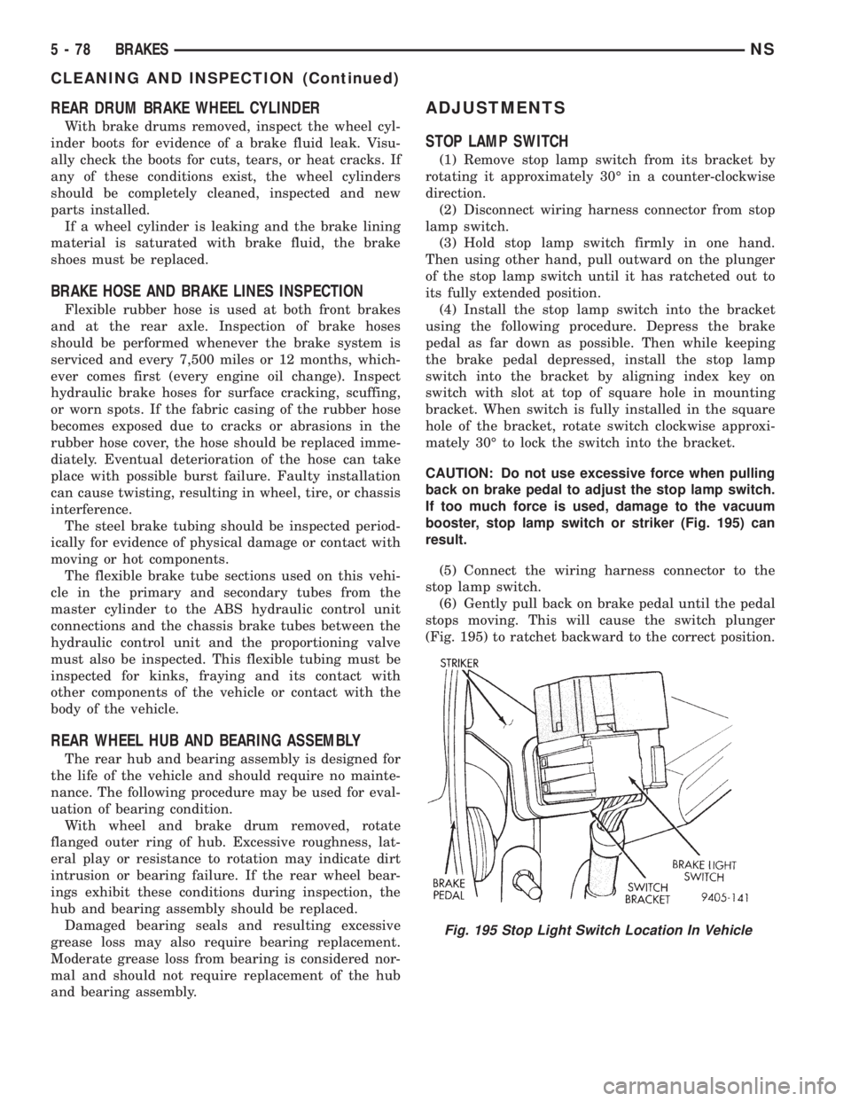
booster, stop lamp switch or striker (Fig. 195) can
result.
(5) Connect the wiring harness connector to the
stop lamp switch.
(6) Gently pull back on brake pedal until the pedal
stops moving. This will cause the switch plunger
(Fig. 195) to ratchet backward to the correct position.
Fig. 195 Stop Light Switch Location In Vehicle
5 - 78 BRAKESNS
CLEANING AND INSPECTION (Continued)